EP1106822A1 - Method and apparatus for starting an engine having a turbocharger - Google Patents
Method and apparatus for starting an engine having a turbocharger Download PDFInfo
- Publication number
- EP1106822A1 EP1106822A1 EP00310675A EP00310675A EP1106822A1 EP 1106822 A1 EP1106822 A1 EP 1106822A1 EP 00310675 A EP00310675 A EP 00310675A EP 00310675 A EP00310675 A EP 00310675A EP 1106822 A1 EP1106822 A1 EP 1106822A1
- Authority
- EP
- European Patent Office
- Prior art keywords
- engine
- turbocharger
- starter
- starting
- crankshaft
- Prior art date
- Legal status (The legal status is an assumption and is not a legal conclusion. Google has not performed a legal analysis and makes no representation as to the accuracy of the status listed.)
- Granted
Links
Images
Classifications
-
- F—MECHANICAL ENGINEERING; LIGHTING; HEATING; WEAPONS; BLASTING
- F02—COMBUSTION ENGINES; HOT-GAS OR COMBUSTION-PRODUCT ENGINE PLANTS
- F02B—INTERNAL-COMBUSTION PISTON ENGINES; COMBUSTION ENGINES IN GENERAL
- F02B37/00—Engines characterised by provision of pumps driven at least for part of the time by exhaust
- F02B37/12—Control of the pumps
- F02B37/18—Control of the pumps by bypassing exhaust from the inlet to the outlet of turbine or to the atmosphere
-
- F—MECHANICAL ENGINEERING; LIGHTING; HEATING; WEAPONS; BLASTING
- F02—COMBUSTION ENGINES; HOT-GAS OR COMBUSTION-PRODUCT ENGINE PLANTS
- F02N—STARTING OF COMBUSTION ENGINES; STARTING AIDS FOR SUCH ENGINES, NOT OTHERWISE PROVIDED FOR
- F02N11/00—Starting of engines by means of electric motors
-
- F—MECHANICAL ENGINEERING; LIGHTING; HEATING; WEAPONS; BLASTING
- F02—COMBUSTION ENGINES; HOT-GAS OR COMBUSTION-PRODUCT ENGINE PLANTS
- F02N—STARTING OF COMBUSTION ENGINES; STARTING AIDS FOR SUCH ENGINES, NOT OTHERWISE PROVIDED FOR
- F02N11/00—Starting of engines by means of electric motors
- F02N11/04—Starting of engines by means of electric motors the motors being associated with current generators
-
- F—MECHANICAL ENGINEERING; LIGHTING; HEATING; WEAPONS; BLASTING
- F02—COMBUSTION ENGINES; HOT-GAS OR COMBUSTION-PRODUCT ENGINE PLANTS
- F02N—STARTING OF COMBUSTION ENGINES; STARTING AIDS FOR SUCH ENGINES, NOT OTHERWISE PROVIDED FOR
- F02N9/00—Starting of engines by supplying auxiliary pressure fluid to their working chambers
- F02N9/04—Starting of engines by supplying auxiliary pressure fluid to their working chambers the pressure fluid being generated otherwise, e.g. by compressing air
-
- Y—GENERAL TAGGING OF NEW TECHNOLOGICAL DEVELOPMENTS; GENERAL TAGGING OF CROSS-SECTIONAL TECHNOLOGIES SPANNING OVER SEVERAL SECTIONS OF THE IPC; TECHNICAL SUBJECTS COVERED BY FORMER USPC CROSS-REFERENCE ART COLLECTIONS [XRACs] AND DIGESTS
- Y02—TECHNOLOGIES OR APPLICATIONS FOR MITIGATION OR ADAPTATION AGAINST CLIMATE CHANGE
- Y02T—CLIMATE CHANGE MITIGATION TECHNOLOGIES RELATED TO TRANSPORTATION
- Y02T10/00—Road transport of goods or passengers
- Y02T10/10—Internal combustion engine [ICE] based vehicles
- Y02T10/12—Improving ICE efficiencies
Definitions
- the present invention relates generally to internal combustion engines for automotive vehicles, and more specifically, to an automotive vehicle having a starter/alternator and a turbocharger coupled to the engine.
- Automotive vehicles with internal combustion engines are typically provided with both a starter motor and alternator.
- a combined alternator and starter motor has been proposed.
- Such systems have a rotor mounted directly to the crankshaft of the engine and a stator sandwiched between the engine block and the bell housing of the transmission.
- the starter/alternator functions as a starter. While functioning as a starter, the starter/alternator rotates the crankshaft of the engine while the cylinders are fired.
- the starter/alternator is used as a generator to charge the electrical system of the vehicle.
- turbochargers are incorporated with the engine. These turbochargers are commonly referred to as exhaust-gas turbochargers.
- a turbocharger consists of two machines: a turbine and a compressor mounted on a common shaft.
- the turbine is coupled to the exhaust system and uses the energy obtained in the flow of the exhaust system to drive the compressor.
- the compressor in turn, draws in outside air, compresses it and supplies it to the cylinders. The compressed air increases the power output of the engine.
- Exhaust gas turbochargers operate using the mass flow of the exhaust gas. Thus, some time is associated with providing enough exhaust gas to rotate the turbocharger at a sufficient speed to provide compression at the output of the turbocharger. Such time is typically referred to as turbo lag. During turbo lag the engine output power is less than that when the turbocharger is operating.
- the engine may be shut down during stops (e.g., red lights).
- stops e.g., red lights.
- the starter/alternator starts the motor and the engine will resume firing.
- many startups may occur over the course of a trip.
- a method of controlling the starting of an internal combustion engine having a starter coupled to the crankshaft of the engine and a turbocharger comprises the steps of: rotating the shaft of the turbocharger to a predetermined speed and starting the engine when the turbocharger reaches the predetermined speed.
- a system for an automotive vehicle comprises an internal combustion engine having a crankshaft coupled to pistons.
- a turbocharger has a rotor that is fluidically coupled to the pistons.
- a starter/alternator is coupled to the crankshaft of the engine.
- a controller is coupled to the starter/alternator to initiate the rotation of the crankshaft to displace air from the pistons and rotate the rotor of the turbocharger. The controller starts the engine upon the rotor reaching a predetermined speed.
- One advantage is that power from the engine may be increased at startup.
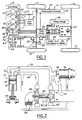
- Figure 1 is a schematic view of an automotive vehicle having a starter/alternator system according to the present invention.
- Figure 2 is a schematic view of a piston of the engine with a turbocharger fluidically coupled thereto.
- the present invention is described with respect to a particular configuration of a starter/alternator. However, the teachings of the present invention may be applied to various starters for internal combustion engines.
- an automotive vehicle 10 having an internal combustion engine 12 having cylinders 14 with pistons 16 located therein.
- Each cylinder 14 is coupled to a fuel pump 18 through a fuel injector (not shown) or other fuel delivery system.
- Each cylinder 14 also has a spark plug 20 or other ignition source coupled to a powertrain control unit.
- a powertrain control unit 22 controls the ignition timing and fuel pump operation 18 in a conventional manner subject to the improvements of the present invention.
- Engine 12 has a turbocharger 24 coupled to the exhaust system (shown below in Figure 2) of engine 12.
- turbocharger 24 is commonly referred to as an exhaust gas turbocharger.
- the present invention applies to superchargers as well.
- Turbocharger as used herein refers to both.
- Engine 12 is coupled to a transmission 26.
- Transmission 26 may be automatic, manual or continuously variable.
- Transmission 26 is coupled to a differential 28 to drive an axle 30 to provide power to wheels 32.
- a starter/alternator system 40 that includes a starter/alternator 42 and its associated control electronics is coupled to engine 12.
- starter/alternator 42 is positioned between a housing 44 of transmission 26 and the engine 12.
- Starter/alternator 42 has a stator fixedly attached to bell housing 44 and a rotor 48 coupled to a crankshaft 50 of engine 12.
- a clutch 52 is used to engage and disengage engine 12 from transmission 26.
- starter/alternator 42 is used as a starter during engine startup and as an alternator to supply power to recharge the batteries of the vehicle and to supply electrical loads.
- Clutch 52 allows starter/alternator 42 to start the engine prior to engagement of the transmission.
- Starter/alternator system 40 has a system controller 54 that is coupled to powertrain control unit 22 and to a power inverter 56.
- the power inverter 56 and system controller 54 may be contained in a single package.
- the inverter 56 is used to convert DC power to AC power in the startup mode and AC power to DC power in power generation mode as will be further described below.
- Power inverter 56 is coupled to an energy storage device 58 such as an ultra capacitor, a first DC to DC converter 60, and a second DC to DC converter 62.
- DC to DC converter 60 is coupled to a 36 volt battery 64.
- DC to DC converter 62 is coupled to a 12 volt battery 66.
- the actual battery voltage is dependent on the particular system to which it is attached.
- a turbocharger 24 is shown coupled to an exhaust system 70 of engine 12 with cylinders 14 and a piston 16. Only one cylinder 14 and piston 16 is shown for simplicity. Piston 16 is coupled to crankshaft 50. Gasses are input and exhausted from cylinders 14 by valves 71, 72, respectively. Although two valves are illustrated, the present invention applies to multi-valve engines. Turbocharger 24 is also coupled to an air intake system 74. A waste gate 76 having a piston 78 may be used to control the pressure into turbocharger 24 by diverting an amount of exhaust gas as is commonly known in the art. Waste gate 76 is a bypass around turbocharger 24.
- Turbocharger 24 has a common rotor shaft 80 that couples the turbine portion 82 to compressor portion 84 of turbocharger 24.
- the turbine portion 82 is caused to rotate which in turn through rotor 80 causes compressor portion 84 to rotate.
- Compressor portion 84 draws in external air through a filter element 86 of an air induction system and compresses the air to force the air into cylinder 14. This compression causes the power output of engine to increase. However, the power is not increased until a sufficient amount of airflow through exhaust system 70 is established. In prior systems, the airflow was exhaust gasses.
- the present invention is particularly applicable to systems in which the engine is completely shut down when the vehicle is at rest, such as at a stop light. In such a system, upon immediate depression of the acceleration pedal a great amount of power is required.
- the starter/alternator provides the required power in a substantially shorter time then the engine firing.
- the rotor shaft 80 of the turbocharger 24 is spun to provide power upon startup of the vehicle.
- the rotor shaft 80 of turbocharger 24 is rotated to a predetermined speed that allows the compressor portion 84 to increase the power of the engine.
- the starting process of engine 12 is initiated by a key placed in the ignition position or the depression of the accelerator pedal (not shown).
- Thirty-six volt battery 64 provides electrical power for starter/alternator 42 which is stepped up to 300 volts by DC to DC converter 60. The 300 volts is used to charge energy storage 58.
- Inverter 56 converts the DC power to three-phase AC power.
- the AC power is supplied to the stator 46 of starter/alternator 42.
- the starter/alternator 42 rotates rotor 48 which in turn rotates crankshaft 50 of engine 12.
- the valves 71, 72 are alternately placed in the open position and closed position depending on the position of the crankshaft which in turn is coupled to the camshaft (not shown) driving the valves.
- the rotation of crankshaft 50 and thus the movement of the pistons 16 causes an amount of air to be displaced into exhaust system 70.
- the starter/alternator 42 is used to displace a sufficient amount of air (i.e., mass airflow) to turn rotor shaft 80 by rotation of the turbine portion 82 of turbocharger 24.
- the compressor portion 84 in turn compresses intake air and provides it to cylinder 14.
- the power input to engine 12 will be increased upon startup of the engine.
- the rotor 80 of turbocharger 24 reaches a predetermined speed, the engine 12 is started by supplying fuel through fuel pump 16 and controlling the spark timing through spark plugs 20 through powertrain control unit 22.
- the turbocharger is increasing the power to engine 12.
- the speed of rotor 80 may be measured directly by using a sensor 90 coupled to shaft to 80.
- the controller 54 may trigger the starting of the combustion process in the engine.
- Another method for determining the speed of rotor 80 is inferring the speed by the amount of time that the engine and thus the pistons 16 have been displacing air into the exhaust system 70. Because the cylinders 14 contain a predetermined volume, the volume and thus the mass airflow of air into the turbine portion 82 of turbocharger 24 may be inferred. The time may be measured by system controller 54.
- the starter/alternator 42 is used in a generating mode.
- the energy storage system 58, and batteries 64, 66 are monitored to determine whether they are fully charged. If any of the energy storage sources drop below a predetermined range, three-phase power from starter/alternator 42 is converted to 300 volts DC by power inverter 56.
- DC to DC converters 60, 62 are used to convert the 300 volts DC to 42 volts and 14 volts respectively. It should be noted that the ultra capacitors of energy storage 58 are charged directly by power converter 56.
Abstract
Description
- The present invention relates generally to internal combustion engines for automotive vehicles, and more specifically, to an automotive vehicle having a starter/alternator and a turbocharger coupled to the engine.
- Automotive vehicles with internal combustion engines are typically provided with both a starter motor and alternator. In recent years, a combined alternator and starter motor has been proposed. Such systems have a rotor mounted directly to the crankshaft of the engine and a stator sandwiched between the engine block and the bell housing of the transmission. During initial startup of the vehicle, the starter/alternator functions as a starter. While functioning as a starter, the starter/alternator rotates the crankshaft of the engine while the cylinders are fired.
- After the engine is started, the starter/alternator is used as a generator to charge the electrical system of the vehicle.
- Many vehicles have turbochargers incorporated with the engine. These turbochargers are commonly referred to as exhaust-gas turbochargers. A turbocharger consists of two machines: a turbine and a compressor mounted on a common shaft. The turbine is coupled to the exhaust system and uses the energy obtained in the flow of the exhaust system to drive the compressor. The compressor in turn, draws in outside air, compresses it and supplies it to the cylinders. The compressed air increases the power output of the engine.
- Exhaust gas turbochargers operate using the mass flow of the exhaust gas. Thus, some time is associated with providing enough exhaust gas to rotate the turbocharger at a sufficient speed to provide compression at the output of the turbocharger. Such time is typically referred to as turbo lag. During turbo lag the engine output power is less than that when the turbocharger is operating.
- In foreseeable automotive applications, the engine may be shut down during stops (e.g., red lights). When the accelerator is depressed, the starter/alternator starts the motor and the engine will resume firing. Thus, many startups may occur over the course of a trip.
- It would therefore be desirable to reduce the amount of turbo lag and thus increase the amount of power of the engine during startup.
- It is therefore one object of the invention to increase the power output of the engine during startup.
- In one aspect of the invention, a method of controlling the starting of an internal combustion engine having a starter coupled to the crankshaft of the engine and a turbocharger comprises the steps of: rotating the shaft of the turbocharger to a predetermined speed and starting the engine when the turbocharger reaches the predetermined speed.
- In a further aspect of the invention, a system for an automotive vehicle comprises an internal combustion engine having a crankshaft coupled to pistons. A turbocharger has a rotor that is fluidically coupled to the pistons. A starter/alternator is coupled to the crankshaft of the engine. A controller is coupled to the starter/alternator to initiate the rotation of the crankshaft to displace air from the pistons and rotate the rotor of the turbocharger. The controller starts the engine upon the rotor reaching a predetermined speed.
- One advantage is that power from the engine may be increased at startup.
- Other objects and features of the present invention will become apparent when viewed in light of the detailed description of the preferred embodiment when taken in conjunction with the attached drawings and appended claims.
- Figure 1 is a schematic view of an automotive vehicle having a starter/alternator system according to the present invention.
- Figure 2 is a schematic view of a piston of the engine with a turbocharger fluidically coupled thereto.
- The present invention is described with respect to a particular configuration of a starter/alternator. However, the teachings of the present invention may be applied to various starters for internal combustion engines.
- Referring now to Figure 1, an
automotive vehicle 10 is illustrated having aninternal combustion engine 12 havingcylinders 14 withpistons 16 located therein. Eachcylinder 14 is coupled to afuel pump 18 through a fuel injector (not shown) or other fuel delivery system. Eachcylinder 14 also has aspark plug 20 or other ignition source coupled to a powertrain control unit. Apowertrain control unit 22 controls the ignition timing andfuel pump operation 18 in a conventional manner subject to the improvements of the present invention. -
Engine 12 has aturbocharger 24 coupled to the exhaust system (shown below in Figure 2) ofengine 12. Thus,turbocharger 24 is commonly referred to as an exhaust gas turbocharger. Also, the present invention applies to superchargers as well. Turbocharger as used herein refers to both. -
Engine 12 is coupled to atransmission 26.Transmission 26 may be automatic, manual or continuously variable.Transmission 26 is coupled to adifferential 28 to drive an axle 30 to provide power towheels 32. Of course, the present invention is also applicable to four wheel drive systems in which all of thewheels 32 are driven. A starter/alternator system 40 that includes a starter/alternator 42 and its associated control electronics is coupled toengine 12. In the present invention, starter/alternator 42 is positioned between ahousing 44 oftransmission 26 and theengine 12. - Starter/alternator 42 has a stator fixedly attached to
bell housing 44 and arotor 48 coupled to acrankshaft 50 ofengine 12. Aclutch 52 is used to engage and disengageengine 12 fromtransmission 26. As will be further described below, starter/alternator 42 is used as a starter during engine startup and as an alternator to supply power to recharge the batteries of the vehicle and to supply electrical loads. Clutch 52 allows starter/alternator 42 to start the engine prior to engagement of the transmission. - Starter/
alternator system 40 has asystem controller 54 that is coupled topowertrain control unit 22 and to apower inverter 56. In practice, thepower inverter 56 andsystem controller 54 may be contained in a single package. Theinverter 56 is used to convert DC power to AC power in the startup mode and AC power to DC power in power generation mode as will be further described below. -
Power inverter 56 is coupled to anenergy storage device 58 such as an ultra capacitor, a first DC toDC converter 60, and a second DC toDC converter 62. DC toDC converter 60 is coupled to a 36volt battery 64. DC toDC converter 62 is coupled to a 12volt battery 66. Of course, the actual battery voltage is dependent on the particular system to which it is attached. - Referring now to Figure 2, a
turbocharger 24 is shown coupled to an exhaust system 70 ofengine 12 withcylinders 14 and apiston 16. Only onecylinder 14 andpiston 16 is shown for simplicity.Piston 16 is coupled tocrankshaft 50. Gasses are input and exhausted fromcylinders 14 byvalves 71, 72, respectively. Although two valves are illustrated, the present invention applies to multi-valve engines.Turbocharger 24 is also coupled to anair intake system 74. Awaste gate 76 having apiston 78 may be used to control the pressure intoturbocharger 24 by diverting an amount of exhaust gas as is commonly known in the art.Waste gate 76 is a bypass aroundturbocharger 24. -
Turbocharger 24 has acommon rotor shaft 80 that couples theturbine portion 82 tocompressor portion 84 ofturbocharger 24. As gasses move from withincylinder 14 through exhaust system 70, theturbine portion 82 is caused to rotate which in turn throughrotor 80 causescompressor portion 84 to rotate.Compressor portion 84 draws in external air through afilter element 86 of an air induction system and compresses the air to force the air intocylinder 14. This compression causes the power output of engine to increase. However, the power is not increased until a sufficient amount of airflow through exhaust system 70 is established. In prior systems, the airflow was exhaust gasses. - In certain operating conditions of a motor vehicle, it may be desirable to provide a greater amount of power from engine upon startup. The present invention is particularly applicable to systems in which the engine is completely shut down when the vehicle is at rest, such as at a stop light. In such a system, upon immediate depression of the acceleration pedal a great amount of power is required. The starter/alternator provides the required power in a substantially shorter time then the engine firing.
- In operation, the
rotor shaft 80 of theturbocharger 24 is spun to provide power upon startup of the vehicle. Therotor shaft 80 ofturbocharger 24 is rotated to a predetermined speed that allows thecompressor portion 84 to increase the power of the engine. The starting process ofengine 12 is initiated by a key placed in the ignition position or the depression of the accelerator pedal (not shown). Thirty-sixvolt battery 64 provides electrical power for starter/alternator 42 which is stepped up to 300 volts by DC toDC converter 60. The 300 volts is used to chargeenergy storage 58.Inverter 56 converts the DC power to three-phase AC power. The AC power is supplied to thestator 46 of starter/alternator 42. The starter/alternator 42 rotatesrotor 48 which in turn rotatescrankshaft 50 ofengine 12. During the startup process, thevalves 71, 72 are alternately placed in the open position and closed position depending on the position of the crankshaft which in turn is coupled to the camshaft (not shown) driving the valves. The rotation ofcrankshaft 50 and thus the movement of thepistons 16 causes an amount of air to be displaced into exhaust system 70. - The starter/alternator 42 is used to displace a sufficient amount of air (i.e., mass airflow) to turn
rotor shaft 80 by rotation of theturbine portion 82 ofturbocharger 24. Thecompressor portion 84 in turn compresses intake air and provides it tocylinder 14. Asrotor shaft 80 turns, the power input toengine 12 will be increased upon startup of the engine. When therotor 80 ofturbocharger 24 reaches a predetermined speed, theengine 12 is started by supplying fuel throughfuel pump 16 and controlling the spark timing throughspark plugs 20 throughpowertrain control unit 22. Thus, as the engine is started, the turbocharger is increasing the power toengine 12. The speed ofrotor 80 may be measured directly by using a sensor 90 coupled to shaft to 80. Thus, uponrotor 80 reaching a sufficient speed, thecontroller 54 may trigger the starting of the combustion process in the engine. - Another method for determining the speed of
rotor 80 is inferring the speed by the amount of time that the engine and thus thepistons 16 have been displacing air into the exhaust system 70. Because thecylinders 14 contain a predetermined volume, the volume and thus the mass airflow of air into theturbine portion 82 ofturbocharger 24 may be inferred. The time may be measured bysystem controller 54. - Once the turbo rotor is turning at a sufficient speed and the engine combustion process is initiated, the starter/alternator 42 is used in a generating mode. In the generating mode, the
energy storage system 58, andbatteries power inverter 56. DC toDC converters energy storage 58 are charged directly bypower converter 56. - While particular embodiments of the invention have been shown and described, numerous variations and alternate embodiments will occur to those skilled in the art. Accordingly, it is intended that the invention be limited only in terms of the appended claims.
Claims (12)
- A method of controlling the starting of an internal combustion engine having a starter coupled to the crankshaft of the engine and a turbocharger having a rotor, said method comprising the steps of:rotating the rotor of the turbocharger to a predetermined speed; andstarting the engine when the turbocharger reaches the predetermined speed.
- A method as recited in claim 1 wherein the predetermined speed is a turbocharger functioning speed.
- A method as recited in claim 1 wherein the step of rotating the rotor shaft comprises the step of generating a mass airflow from the engine and coupling the mass airflow to said rotor shaft of the turbocharger.
- A method as recited in claim 3 wherein the step of rotating the rotor shaft comprises rotating the crankshaft of the vehicle with a starter and wherein the step of generating a mass airflow comprises the step of displacing air by moving pistons coupled to the crankshaft.
- A method as recited in claim 1 wherein the step of starting the engine comprises the step of operating the fuel pump; and providing fuel to cylinders of the engine.
- A method as recited in claim 1 further comprising the step of inferring the speed of the rotor shaft of the turbocharger from the crankshaft of the engine.
- A method as recited in claim 1 further comprising the step of generating power from the starter after the step of starting the engine.
- A method of stating a vehicle with a starter and an internal combustion engine comprising the steps of:rotating the crankshaft of the vehicle with the starter;moving pistons in a respective cylinder;displacing air into the exhaust system with the piston;rotating a shaft of the turbocharger with the displaced air to a functioning speed; andstarting the engine when the turbocharger reaches the starting speed.
- A method as recited in claim 8 wherein the step of rotating the rotor shaft comprises the step of generating a mass airflow from the engine and coupling the mass airflow to said rotor shaft of the turbocharger.
- A method as recited in claim 8 wherein the step of starting the engine comprises the step of operating the fuel pump; and providing fuel to cylinders of the engine.
- A method as recited in claim 8 further comprising the step of inferring the speed of the rotor shaft of the turbocharger from the crankshaft of the engine.
- A method as recited in claim 8 further comprising the step of generating power from the starter after the step of starting the engine.
Applications Claiming Priority (2)
| Application Number | Priority Date | Filing Date | Title |
|---|---|---|---|
| US455686 | 1989-12-22 | ||
| US09/455,686 US6233935B1 (en) | 1999-12-07 | 1999-12-07 | Method and apparatus for starting an engine having a turbocharger |
Publications (2)
| Publication Number | Publication Date |
|---|---|
| EP1106822A1 true EP1106822A1 (en) | 2001-06-13 |
| EP1106822B1 EP1106822B1 (en) | 2003-10-15 |
Family
ID=23809856
Family Applications (1)
| Application Number | Title | Priority Date | Filing Date |
|---|---|---|---|
| EP00310675A Expired - Fee Related EP1106822B1 (en) | 1999-12-07 | 2000-12-01 | Method and apparatus for starting an engine having a turbocharger |
Country Status (4)
| Country | Link |
|---|---|
| US (2) | US6233935B1 (en) |
| EP (1) | EP1106822B1 (en) |
| JP (1) | JP2001193614A (en) |
| DE (1) | DE60005914T2 (en) |
Cited By (1)
| Publication number | Priority date | Publication date | Assignee | Title |
|---|---|---|---|---|
| WO2018068880A1 (en) * | 2016-10-10 | 2018-04-19 | Ihi Charging Systems International Gmbh | Exhaust-gas guide section for a turbocharger, exhaust system for an internal combustion engine and method for operating a turbocharger |
Families Citing this family (19)
| Publication number | Priority date | Publication date | Assignee | Title |
|---|---|---|---|---|
| US6364042B1 (en) * | 2000-04-26 | 2002-04-02 | Ford Global Technologies, Inc. | Method and apparatus for coupling an engine and transmission with a starter/alternator |
| US6962135B2 (en) | 2002-01-31 | 2005-11-08 | Visteon Global Technologies, Inc. | Use of integrated starter alternator to prevent engine stall |
| ITCE20020009A1 (en) * | 2002-09-30 | 2002-12-30 | Giuseppe Ferraro | REVERSIBLE BALLET IMPELLER DEVICE WITH ELECTRIC MOTOR / GENERATOR "WITHOUT BRUSHES" FOR THE MANAGEMENT OF THE SUPPLY AIR |
| JP2005042684A (en) * | 2003-07-25 | 2005-02-17 | Denso Corp | Power control device for turbo charger with electric motor and motor-driven turbo charger device |
| US7093589B2 (en) * | 2004-01-08 | 2006-08-22 | Visteon Global Technologies, Inc. | Apparatus for increasing induction air flow rate to a turbocharger |
| US8205450B2 (en) * | 2004-05-07 | 2012-06-26 | Honeywell International Inc. | Method of operating an electrically assisted turbocharger and a boosting device |
| US7105937B2 (en) * | 2004-07-14 | 2006-09-12 | Hamilton Sundstrand Corporation | Adjustable variable frequency starter/generator system |
| US7877997B2 (en) * | 2008-02-28 | 2011-02-01 | Caterpillar Inc. | Wastegate control system based on variable valve actuation |
| US8245801B2 (en) * | 2009-11-05 | 2012-08-21 | Bluways Usa, Inc. | Expandable energy storage control system architecture |
| US8627803B2 (en) * | 2010-11-17 | 2014-01-14 | GM Global Technology Operations LLC | Variable displacement engine assembly including partial boost arrangement |
| CN103444048B (en) | 2011-04-08 | 2015-09-23 | 三菱电机株式会社 | Automotive power supply system |
| US8374742B2 (en) * | 2011-09-16 | 2013-02-12 | Ford Global Technologies, Llc | Turbocharger launch control |
| CN102678284A (en) * | 2012-05-03 | 2012-09-19 | 上海交通大学 | Mechanical regulating type turbine bleeding system |
| CN102678283A (en) * | 2012-05-03 | 2012-09-19 | 上海交通大学 | Engine exhaust gas bypass device |
| US9174525B2 (en) | 2013-02-25 | 2015-11-03 | Fairfield Manufacturing Company, Inc. | Hybrid electric vehicle |
| US9731609B2 (en) | 2014-04-04 | 2017-08-15 | Dg Systems Llc | Vehicle power sharing and grid connection system for electric motors and drives |
| FR3031635B1 (en) | 2015-01-08 | 2018-05-04 | Airbus Helicopters | GIRAVION WITH ELECTRICAL EQUIPMENT REGULATING THE POWER SUPPLY OF A STARTING PHASE TURBOMOTOR |
| DE102015210079A1 (en) * | 2015-06-01 | 2016-12-01 | Volkswagen Aktiengesellschaft | Method and control device for operating a drive device |
| CN104895668A (en) * | 2015-06-28 | 2015-09-09 | 钱蔚鑫 | Through hole flow type waste gas bypass system |
Citations (3)
| Publication number | Priority date | Publication date | Assignee | Title |
|---|---|---|---|---|
| US4781028A (en) * | 1985-07-25 | 1988-11-01 | Michael Zoche | Turbocharged diesel engine |
| DE19529740A1 (en) * | 1995-08-12 | 1997-02-13 | Bayerische Motoren Werke Ag | Electric starter motor for IC engine - which also drives the turbocharger via an intermediate transmission. |
| US5704323A (en) * | 1993-12-08 | 1998-01-06 | Scania Cv Aktiebolag | Arrangement in - and method for starting - an internal combustion engine |
Family Cites Families (13)
| Publication number | Priority date | Publication date | Assignee | Title |
|---|---|---|---|---|
| US1752224A (en) * | 1928-12-07 | 1930-03-25 | Vincent G Apple | Combined electric starter, battery recharger, and engine supercharger |
| US2585029A (en) * | 1947-10-23 | 1952-02-12 | Nettel Frederick | Self-powered turbosupercharger starter system for internalcombustion engines |
| US2654991A (en) * | 1950-09-09 | 1953-10-13 | Nettel Frederick | Control for engine turbosupercharger systems |
| GB1292955A (en) * | 1968-11-11 | 1972-10-18 | Plessey Co Ltd | Improvements in or relating to the starting of diesel engines |
| US4699097A (en) | 1984-08-31 | 1987-10-13 | Mazda Motor Corporation | Means for suppressing engine output torque fluctuations |
| FR2604041B1 (en) | 1986-09-11 | 1988-10-28 | Valeo | METHOD FOR CONTROLLING A REVERSIBLE GENERATOR-MOTOR ELECTRIC MACHINE FOR A MOTOR VEHICLE, AND CONTROL UNIT FOR IMPLEMENTING SUCH A METHOD |
| JP2511932B2 (en) | 1987-02-27 | 1996-07-03 | 株式会社日立製作所 | Torque control device for internal combustion engine |
| JPH0691759B2 (en) | 1988-08-12 | 1994-11-14 | 株式会社日立製作所 | Power generation control device for internal combustion engine |
| JPH0297300A (en) | 1988-09-30 | 1990-04-09 | Aisin Seiki Co Ltd | Portable type engine generator |
| JP2987859B2 (en) * | 1989-12-28 | 1999-12-06 | いすゞ自動車株式会社 | Control device for turbocharger with rotating electric machine |
| JPH04342828A (en) * | 1991-05-20 | 1992-11-30 | Isuzu Motors Ltd | Control device for turbocharger provided with rotary electric equipment |
| JP3232635B2 (en) * | 1992-02-19 | 2001-11-26 | いすゞ自動車株式会社 | Control device for turbocharger with rotating electric machine |
| JP3202632B2 (en) | 1997-01-20 | 2001-08-27 | 松下電器産業株式会社 | Circuit function inspection device |
-
1999
- 1999-12-07 US US09/455,686 patent/US6233935B1/en not_active Ceased
-
2000
- 2000-12-01 DE DE60005914T patent/DE60005914T2/en not_active Expired - Fee Related
- 2000-12-01 EP EP00310675A patent/EP1106822B1/en not_active Expired - Fee Related
- 2000-12-04 JP JP2000368018A patent/JP2001193614A/en active Pending
-
2001
- 2001-09-25 US US09/962,992 patent/USRE38671E1/en not_active Expired - Fee Related
Patent Citations (3)
| Publication number | Priority date | Publication date | Assignee | Title |
|---|---|---|---|---|
| US4781028A (en) * | 1985-07-25 | 1988-11-01 | Michael Zoche | Turbocharged diesel engine |
| US5704323A (en) * | 1993-12-08 | 1998-01-06 | Scania Cv Aktiebolag | Arrangement in - and method for starting - an internal combustion engine |
| DE19529740A1 (en) * | 1995-08-12 | 1997-02-13 | Bayerische Motoren Werke Ag | Electric starter motor for IC engine - which also drives the turbocharger via an intermediate transmission. |
Cited By (1)
| Publication number | Priority date | Publication date | Assignee | Title |
|---|---|---|---|---|
| WO2018068880A1 (en) * | 2016-10-10 | 2018-04-19 | Ihi Charging Systems International Gmbh | Exhaust-gas guide section for a turbocharger, exhaust system for an internal combustion engine and method for operating a turbocharger |
Also Published As
| Publication number | Publication date |
|---|---|
| DE60005914T2 (en) | 2004-08-19 |
| DE60005914D1 (en) | 2003-11-20 |
| EP1106822B1 (en) | 2003-10-15 |
| USRE38671E1 (en) | 2004-12-21 |
| US6233935B1 (en) | 2001-05-22 |
| JP2001193614A (en) | 2001-07-17 |
Similar Documents
| Publication | Publication Date | Title |
|---|---|---|
| US6233935B1 (en) | Method and apparatus for starting an engine having a turbocharger | |
| US6781252B2 (en) | Method and apparatus for starting an engine using a starter/alternator and an accessory drive | |
| US8225608B2 (en) | Hybrid powertrain and method for controlling a hybrid powertrain | |
| US6338391B1 (en) | Hybrid vehicles incorporating turbochargers | |
| US8136615B2 (en) | Method for operating an internal combustion engine | |
| US20070151241A1 (en) | Electric boost compressor and turbine generator system | |
| US20130233268A1 (en) | Engine starting apparatus | |
| JPH0580582B2 (en) | ||
| JP4075699B2 (en) | Vehicle control device | |
| US20090118980A1 (en) | Control apparatus and method for internal combustion engine | |
| JP2002512342A (en) | Method and starter system for starting an internal combustion engine | |
| EP0857250A1 (en) | Charge air systems for two-cycle internal combustion engines | |
| US10060403B2 (en) | System for controlling starting of engine | |
| US9790879B2 (en) | Controller for starting vehicular direct-injection engine | |
| US6382163B1 (en) | Starter alternator with variable displacement engine and method of operating the same | |
| JP3925336B2 (en) | Internal combustion engine stop / start control device | |
| US5307632A (en) | Engine and method for turbo boosted operation of a mechanically assisted turbocharger in a two cycle engine | |
| CN114165340A (en) | Belt-driven starter-generator assisted engine shutdown | |
| US20070142165A1 (en) | Method for operating a drive system | |
| JP3956953B2 (en) | Power output apparatus, automobile equipped with the same, and control method of power output apparatus | |
| KR102072840B1 (en) | Method for cold-starting a heat engine and associated drive device | |
| US10221781B1 (en) | Hybrid vehicle with turbo lag reduction apparatus | |
| EP1106824A1 (en) | Method and apparatus for starting an engine using an engine torque matching starter | |
| US11761400B2 (en) | Engine device | |
| JP3721987B2 (en) | Start control device for internal combustion engine |
Legal Events
| Date | Code | Title | Description |
|---|---|---|---|
| PUAI | Public reference made under article 153(3) epc to a published international application that has entered the european phase |
Free format text: ORIGINAL CODE: 0009012 |
|
| AK | Designated contracting states |
Kind code of ref document: A1 Designated state(s): DE GB SE |
|
| AX | Request for extension of the european patent |
Free format text: AL;LT;LV;MK;RO;SI |
|
| 17P | Request for examination filed |
Effective date: 20011127 |
|
| AKX | Designation fees paid |
Free format text: DE GB SE |
|
| 17Q | First examination report despatched |
Effective date: 20020130 |
|
| GRAH | Despatch of communication of intention to grant a patent |
Free format text: ORIGINAL CODE: EPIDOS IGRA |
|
| GRAS | Grant fee paid |
Free format text: ORIGINAL CODE: EPIDOSNIGR3 |
|
| GRAA | (expected) grant |
Free format text: ORIGINAL CODE: 0009210 |
|
| AK | Designated contracting states |
Kind code of ref document: B1 Designated state(s): DE GB SE |
|
| REG | Reference to a national code |
Ref country code: GB Ref legal event code: FG4D |
|
| REF | Corresponds to: |
Ref document number: 60005914 Country of ref document: DE Date of ref document: 20031120 Kind code of ref document: P |
|
| PG25 | Lapsed in a contracting state [announced via postgrant information from national office to epo] |
Ref country code: SE Free format text: LAPSE BECAUSE OF FAILURE TO SUBMIT A TRANSLATION OF THE DESCRIPTION OR TO PAY THE FEE WITHIN THE PRESCRIBED TIME-LIMIT Effective date: 20040115 |
|
| PGFP | Annual fee paid to national office [announced via postgrant information from national office to epo] |
Ref country code: DE Payment date: 20040522 Year of fee payment: 4 |
|
| PLBE | No opposition filed within time limit |
Free format text: ORIGINAL CODE: 0009261 |
|
| STAA | Information on the status of an ep patent application or granted ep patent |
Free format text: STATUS: NO OPPOSITION FILED WITHIN TIME LIMIT |
|
| 26N | No opposition filed |
Effective date: 20040716 |
|
| PG25 | Lapsed in a contracting state [announced via postgrant information from national office to epo] |
Ref country code: GB Free format text: LAPSE BECAUSE OF NON-PAYMENT OF DUE FEES Effective date: 20041201 |
|
| PG25 | Lapsed in a contracting state [announced via postgrant information from national office to epo] |
Ref country code: DE Free format text: LAPSE BECAUSE OF NON-PAYMENT OF DUE FEES Effective date: 20050701 |
|
| GBPC | Gb: european patent ceased through non-payment of renewal fee |
Effective date: 20041201 |