EP1106802A1 - V-engine cooling device - Google Patents
V-engine cooling device Download PDFInfo
- Publication number
- EP1106802A1 EP1106802A1 EP00937227A EP00937227A EP1106802A1 EP 1106802 A1 EP1106802 A1 EP 1106802A1 EP 00937227 A EP00937227 A EP 00937227A EP 00937227 A EP00937227 A EP 00937227A EP 1106802 A1 EP1106802 A1 EP 1106802A1
- Authority
- EP
- European Patent Office
- Prior art keywords
- engine
- banks
- cooling water
- cooling
- connection tube
- Prior art date
- Legal status (The legal status is an assumption and is not a legal conclusion. Google has not performed a legal analysis and makes no representation as to the accuracy of the status listed.)
- Granted
Links
Images

Classifications
-
- F—MECHANICAL ENGINEERING; LIGHTING; HEATING; WEAPONS; BLASTING
- F01—MACHINES OR ENGINES IN GENERAL; ENGINE PLANTS IN GENERAL; STEAM ENGINES
- F01P—COOLING OF MACHINES OR ENGINES IN GENERAL; COOLING OF INTERNAL-COMBUSTION ENGINES
- F01P3/00—Liquid cooling
- F01P3/02—Arrangements for cooling cylinders or cylinder heads
-
- F—MECHANICAL ENGINEERING; LIGHTING; HEATING; WEAPONS; BLASTING
- F01—MACHINES OR ENGINES IN GENERAL; ENGINE PLANTS IN GENERAL; STEAM ENGINES
- F01P—COOLING OF MACHINES OR ENGINES IN GENERAL; COOLING OF INTERNAL-COMBUSTION ENGINES
- F01P11/00—Component parts, details, or accessories not provided for in, or of interest apart from, groups F01P1/00 - F01P9/00
- F01P11/08—Arrangements of lubricant coolers
-
- F—MECHANICAL ENGINEERING; LIGHTING; HEATING; WEAPONS; BLASTING
- F01—MACHINES OR ENGINES IN GENERAL; ENGINE PLANTS IN GENERAL; STEAM ENGINES
- F01P—COOLING OF MACHINES OR ENGINES IN GENERAL; COOLING OF INTERNAL-COMBUSTION ENGINES
- F01P3/00—Liquid cooling
- F01P3/20—Cooling circuits not specific to a single part of engine or machine
-
- F—MECHANICAL ENGINEERING; LIGHTING; HEATING; WEAPONS; BLASTING
- F02—COMBUSTION ENGINES; HOT-GAS OR COMBUSTION-PRODUCT ENGINE PLANTS
- F02B—INTERNAL-COMBUSTION PISTON ENGINES; COMBUSTION ENGINES IN GENERAL
- F02B75/00—Other engines
- F02B75/16—Engines characterised by number of cylinders, e.g. single-cylinder engines
- F02B75/18—Multi-cylinder engines
- F02B75/22—Multi-cylinder engines with cylinders in V, fan, or star arrangement
-
- F—MECHANICAL ENGINEERING; LIGHTING; HEATING; WEAPONS; BLASTING
- F01—MACHINES OR ENGINES IN GENERAL; ENGINE PLANTS IN GENERAL; STEAM ENGINES
- F01P—COOLING OF MACHINES OR ENGINES IN GENERAL; COOLING OF INTERNAL-COMBUSTION ENGINES
- F01P11/00—Component parts, details, or accessories not provided for in, or of interest apart from, groups F01P1/00 - F01P9/00
- F01P11/04—Arrangements of liquid pipes or hoses
-
- F—MECHANICAL ENGINEERING; LIGHTING; HEATING; WEAPONS; BLASTING
- F01—MACHINES OR ENGINES IN GENERAL; ENGINE PLANTS IN GENERAL; STEAM ENGINES
- F01P—COOLING OF MACHINES OR ENGINES IN GENERAL; COOLING OF INTERNAL-COMBUSTION ENGINES
- F01P2060/00—Cooling circuits using auxiliaries
- F01P2060/04—Lubricant cooler
Definitions
- the present invention relates to cooling systems for a V-type engine including a V-type diesel engine.
- a water cooling system used in a V-type engine has the following structure and function (e.g., Japanese Patent Application, Laid Open Publication Nos. 62-91615 and 7-189694).
- Awater pump is attached to one end of an engine in a crankshaft direction, and cooling water discharged from the water pump is distributed to both banks of the engine such that it flows through the banks in the crankshaft direction.
- the cooling water is then collected into a collection pipe at the other end of the engine and introduced to a radiator. Subsequently, the cooling water is returned to the water pump from the radiator.
- an oil cooler of water-cooled type is sometimes provided for cooling an oil.
- the cooling water which has cooled the engine is used as a cooling medium for cooling the oil, the oil may not be sufficiently cooled since the cooling water is already hot.
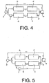
- the cooling water is bifurcated immediately downstream of the water pump "a” and one branch flow of cooling water passes the oil cooler "f" prior to entering the cylinder block "b" of one of the banks.
- the cooling water is drawn out from an upstream portion of the cylinder block "b" of one of the banks and introduced to the oil cooler "f" and collection pipe “d.” According to these arrangements, the cooling water before used for cooling the engine is employed as the oil cooling medium so that sufficient oil cooling can be expected.
- the conventional arrangements cannot realize both the good cooling balance between the two banks and the good oil cooling performance.
- the water pump is located at a front end of the engine and the collection pipe is located at the rear end of the engine.
- An object of the present invention is to realize both the good cooling balance between the two banks and the good oil cooling performance.
- Another object of the present invention is to equalize the temperature and amount of cooling water introduced to the two banks so that there is no temperature difference between the banks.
- Still another object of the present invention is to design a compact engine.
- Yet another object of the present invention is to eliminate a separate pipe connecting the banks so that the number of parts required is reduced and a layout problem does not arise in the engine room.
- Another object of the present invention is to improve rigidity and reduce vibration noise.
- a cooling system for a V-type engine characterized in that cooling water supplied from a water pump is distributed to two banks of the engine after the cooling water passes an oil cooler.
- cooling water Since the cooling water is introduced to the oil cooler before it cools the engine, it can cool the oil sufficiently. Further, since the cooling water is introduced to the banks after passing the oil cooler, temperature and amount of the cooling water to be entered to the two banks are equal. Thus, there is no temperature difference between the banks.
- the water pump is provided at an end of the engine in a crankshaft direction and a connection pipe connecting water jackets of the banks is provided at the other end of the engine such that the cooling water discharged from the water pump is caused to flow in the connection pipe after the oil cooler and is introduced to the water jackets of the banks from the connection pipe.
- connection pipe has an inlet for accepting the cooling water from the oil cooler, at least two outlets positioned in series in a flow direction of the cooling water from the inlet and communicated with water jackets of the banks of the engine respectively, and a throttle portion between the outlets for reducing a cross section of the connection tube.
- connection tube is preferably tapered between the outlets such that the connection tube is more throttled as it goes upstream, a most throttled portion preferably defines the throttle portion, and the throttle portion is preferably located immediately downstream of the upstream outlet.
- connection tube is integrally formed on a flywheel housing.
- a cooling system for a V-type engine characterized in that a connection tube for connecting water jackets of two banks of an engine is integrally formed with a housing member mounted on an end of the engine in a crankshaft direction.
- the housing member which is generally mounted on an end of the engine in the crankshaft direction is used to integrally form the connection tube, a separate pipe is unnecessary and therefore easy layout and size reduction are realized.
- the housing member is a flywheel housing.
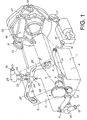
- the V-type engine 1 has right and left banks 2 and 3, and a cylinder block 4 is situated below these banks 2 and 3. On the top of the banks, provided are cylinder heads 5 and 6.
- a crank gear 7 is mounted on one end (front end) of a crankshaft (not shown) of the engine 1, and an idle gear 8 and pump gear 9 are rotatably provided at the front end of the engine 1 such that the gears 8 and 9 are driven (rotated) by the crank gear 7.
- a water pump 10 is also mounted on the front end of the engine 1 such that it is driven by the pump gear 9.
- the water pump 10 has two inlets 11 and 12 to accept the cooling water and one outlet 13 to discharge the cooling water. In the drawing, the unshaded arrow indicates a flow direction of cooling water.
- the outlet 13 of the water pump 10 projects to the right of the engine 1 and is directed to the rear.
- the cooler inlet tube 14 extends to the rear and its downstream end (outlet) connects to a cooling water inlet 16 of a water-cooled oil cooler 15.
- the oil (engine lubrication oil) and cooling water are heat-exchanged with each other to cool the oil.
- the exit of the oil cooler 15 is communicated with a bent coupling tube 17.
- the oil cooler 15 is located at an mid position of the engine 1 in the crankshaft direction such that the longitudinal direction of the oil cooler matches the crankshaft direction.
- the oil cooler 15 has an exit in a rear portion thereof in its longitudinal direction, and the coupling tube 17 extends from the oil cooler exit.
- the liaison tube 17 bends at its mid way and directed to the left, and the exit of the liaison tube 17 is connected to an entrance 19 of a bridge tube 18.
- the bridge tube 18 connects the right and left banks 2 and 3 of the engine 1. Specifically, it spans a left water jacket (not shown) and a right water jacket (not shown) of the cylinder block 4.
- the bridge tube 18 is integrally formed with a flywheel housing 20, which is a housing member in the claims. Therefore, the flywheel housing 20, which is normally mounted on the rear end of the engine 1 in the crankshaft direction, is utilized to provide/define the bridging tube 18.
- the bridging tube 18 extends in right and left directions, and has an inlet 19 at its right end and two outlets 21 formed in series and spaced from the inlet 19 in the longitudinal direction of the tube (flow direction of the cooling water). These outlets 21 are directly communicated with the water jackets of the right and left banks 2 and 3.
- exit tubes 22 and 23 extend from the front faces of the cylinder heads 5 and 6 respectively. These exit tubes 22 and 23 meet at the center between the banks 2 and 3. Specifically, the exit tubes extend to a thermostat casing 24. Two thermostats 25 and 26 are received in the thermostat casing 24. One of them 25 is a two-stage open type, and the other one 26 is a single stage open type. A bypass outlet 27 is provided on a bottom of the thermostat casing 24, and a bypass tube 28 extends therefrom to the bypass inlet 11 of the water pump 10.
- thermostat housing 24 An upper portion of the thermostat housing 24 is a housing cover 29 which is openable.
- the housing cover 29 has an outlet 30, which is connected to an inlet of the radiator (not shown) by a pipe (not shown).
- An outlet of the radiator is connected to the inlet 12 of the water pump 10 by a tube (not shown).
- the cooling water supplied from the water pump 10 is directed to the rear in the cooler inlet pipe 14 and introduced to the oil cooler 15.
- the cooling water heat-exchanges with the oil and flows into the liaison tube 17 and bridging tube 18.
- the cooling water is first introduced to the cylinder block 4 of the right bank 3 from the bridging tube 18, and then introduced to the cylinder block 4 of the left bank 2.
- the bridging tube 18 distributes the cooling water to the respective banks 2 and 3.
- the cooling water flows from the rear to the front. In the meantime, some cooling water ascends toward the cylinder heads 5 and 6. These flows of the cooling water cools the engine 1. After passing through the banks 2 and 3, the cooling water is introduced to the exit pipes 22 and 23 and in turn to the thermostat housing 24. When the thermostats 25 and 26 are both closed, all the cooling water is returned to the water pump 10 from the thermostat housing 24 via the bypass pipe 28. Thus, the cooling water does not go through the radiator so that it is not cooled. This occurs when the engine is just started, i.e., in a warm-up condition or the like.
- the cooling water is allowed to flow to the upwards through the thermostats 25 and 26 in an amount (or flow rate) determined by the opening degree of the thermostats. Then the cooling water is directed to the radiator via the pipe (not shown) from the exit 30 of the thermostat housing. The cooling water is cooled in the radiator, and returned to the water pump 10 via the pipe (not shown) from the inlet 12 of the water pump 10. The reminder of the cooling water which does not flow into the radiator is bypassed to the water pump 10 through the bypass line 28.
- the engine 1 has pipes and routes, which extend through a heater core for heating a passenger compartment of a vehicle.
- the cooling water is replenished by feeding the cooling water to the radiator from a reserve tank.
- the cooling water supplied from the water pump 10 is caused to flow into the oil cooler 15 prior to introduction to the engine, the oil is cooled with the cold cooling water and therefore the cooling water can demonstrate sufficient oil cooling performance.
- the cooling water is equally distributed to the banks 2 and 3 of the engine 1 after passing through the oil cooler 15, no temperature difference arises between the banks 2 and 3. In this manner, both the good oil cooling performance and the good cooling balance between the banks are realized.
- the bridging tube 18 is provided at the other end of the engine, the cooling water supplied from the water pump 10 is introduced to the bridging tube 18 after the coil cooler 15 and it is then distributed to the water jackets of the two banks 2 and 3 of the engine 1 from the bridging tube 18, it is possible to design the engine 1 compact.
- the cooling water from the water pump 10 at the engine front is first fed to the engine rear, and on its way the cooling water passes the oil cooler 15.
- the cooling water is then introduced to the banks 2 and 3 from the engine rear and returned to the water pump 10 at the front. If the cooling water flows into the oil cooler 15 at the engine front, and simultaneously the cooling water is fed to the right and left banks 2 and 3 from the front, then the piping and oil cooler 15 should be crowdedly located at the engine front. This makes the engine part layout complicated at the engine front and makes the engine larger. Further, one pipe is required to return the cooling water from the engine rear to the front.
- the engine parts can be located in an efficient manner so that it is possible to design a compact engine.
- the oil cooler 15 is located at a mid point of the engine 1 in the crankshaft direction and beside the engine 1, and extends in the crankshaft direction, the length of the oil cooler 15 is effectively utilized to reduce the length of the pipes connecting the engine front to the engine rear (namely, the pipes 14 and 17).
- the illustrated arrangement has another remarkable feature that the bridging pipe 18 is integrally formed with/on the flywheel housing 20.
- the structure of the flywheel housing 20 will be described in detail.
- the flywheel housing 20 is a single cast product, and a rib 31 projecting from a front face of the flywheel housing engages with a rear face of the engine 1.
- the flywheel housing 20 is secured to the engine by a plurality of bolts.
- Reference numeral 32 designates bolt holes.
- a flywheel is located behind the housing 20 and its outer periphery is covered.
- the flywheel housing 20 has a center opening 33 for passage of a rear end of the crankshaft.
- Reference numeral 34 denotes a reinforcement rib that spans the attachment rib 31 transversely and also extends along the periphery of the center opening 33.
- connection tube 18 is formed integral with an upper portion of the flywheel housing 20.
- the connection tube 18 extends transversely and has a rectangular cross section, which is elongated in the vertical direction.
- the forwardly directed outlets 21 are provided outside and near the attachment rib 31.
- the connection tube 18 bends diagonally downward, and the free end is the inlet 19.
- the left free end of the connection tube 18 is not connected to any parts; instead, it is closed by a cap 35 as illustrated in Figure 1 so that the cooling water does not escape.
- the attachment rib 31 projects forward more than the connection tube 18.
- the outlet 21 is enlarged stepwise to define a shoulder 36 which is coupled to a tubular element (not shown) extending from the cylinder block 4 by a faucet joint.
- This tubular element is an inlet of the water jacket of the associated bank.
- An annular portion 37 which also defines the enlarged portion 36 forms a very small gap 38 between itself and the rib 31.
- the annular portion 37 projects to the same extent as the rib 31.
- connection tube 18 is preferably tapered from the left outlet 21 to the right outlet 21 (i.e., to the upstream).
- the whole pipe segment on the left side from the bending position A i.e., spanning portion 39
- the bending position A is immediate left (immediate downstream) of a center O of the right outlet 21.
- the water passage area (cross section) of the connection tube 18 is most throttled at the bending position A In this manner, a throttle portion 40 is defined at the bending position A of the connection tube 18.
- connection tube 18 bends at the bending position A, and has an inlet portion 41 on its right side.
- This inlet portion is tapered in the opposite manner. Specifically, it is tapered toward the left (or toward the downstream). However, the taper is gentler than the spanning portion 39.
- the right end of the inlet portion 41 is the inlet 19. In this manner, the connection tube 18 has the inlet 19, right outlet 21 and left outlet 21 in series in this order in the cooling water flow direction.
- connection tube 18 By forming the connection tube 18 integrally with the flywheel housing 20, a separate connection tube (collection tube) which is required in a conventional arrangement is eliminated and therefore the number of parts is reduced and a cost is reduced.
- the flywheel housing is mounted on the rear of the engine so that the illustrated arrangement takes advantage of it to provide the connection tube. Since one pipe is dispensed with, a space therefore is left. Thus, freedom in the layout is raised and it becomes easier to arrange other parts. Accordingly, the engine rear becomes compact.
- connection tube 18 serves as a reinforcing rib, rigidity of the flywheel housing 20 and in turn the engine as a whole are improved. This contributes to vibration noise reduction.
- the throttle portion 40 equalizes the amounts of cooling water passing through the respective outlets 21, it greatly contributes to elimination of temperature difference between the banks 2 and 3.
- the right outlet 21 is positioned immediately downstream of the bent pipe 17.
- the bending of the pipe 17 causes the cooling water to tend to deflect toward the back of the tube at the right outlet 21. If it were not for the throttle portion 40, the cooling water would flow mostly along the coupling tube 17 at the right outlet 21 in some flow rate conditions and therefore it would be difficult for the cooling water to flow into the perpendicular right outlet 21.
- the cooling water pipe downstream of the right outlet 21 is throttled and becomes a resistance so that the cooling water is easily able to enter the right outlet 21.
- connection tube 18 may have a plurality of outlets for each of the banks, and the throttle portion may be a projection instead of the taper.
- connection tube 18 may be integrally formed with any housing member spanning the two banks instead of the flywheel housing 20.
- connection tube 18 is used as a pipe for introducing the cooling water to the banks, but it may be replaced by a collection tube of a conventional arrangement which gathers the cooling water from the banks.
- an idea of forming the connection tube 18 integrally with the housing member is applicable to the conventional arrangement.
- the present invention is applicable to various V-type engines such as V-type diesel and gasoline engines.
Landscapes
- Engineering & Computer Science (AREA)
- Chemical & Material Sciences (AREA)
- Combustion & Propulsion (AREA)
- Mechanical Engineering (AREA)
- General Engineering & Computer Science (AREA)
- Lubrication Of Internal Combustion Engines (AREA)
Abstract
Description
Claims (7)
- A cooling system for a V-type engine characterized in that cooling water supplied from a water pump (10) is distributed to both banks (2, 3) of an engine (1) after passing through an oil cooler (15).
- The cooling system for a V-type engine according to claim 1, characterized in that the water pump (10) is mounted on one end of the engine (1) in a crankshaft direction, a connection tube (18) for connecting water jackets of the banks (2, 3) of the engine (1) is mounted on the other end of the engine (1), the cooling water supplied from the water pump (10) is fed to the connection tube (18) after passing through the oil cooler (15), and the cooling water is further fed to the water jackets of the banks (2, 3) from the connection tube (18).
- The cooling system for a V-type engine according to claim 2, characterized in that the connection tube (18) includes an inlet (19) for accepting the cooling water after the oil cooler (15), at least two outlets (21, 21) positioned in series in a flow direction of the cooling water from the inlet (19) and communicated with water jackets of the banks (2, 3) of the engine (1) respectively, and a throttle portion (40) between the outlets (21, 21) for reducing a cross section of the connection tube.
- The cooling system for a V-type engine according to claim 3, characterized in that the connection tube (18) is tapered between the outlets (21, 21) such that the connection tube is more throttled as it goes upstream and a most throttled portion defines the throttle portion (40), and the throttle portion is located immediately downstream of the upstream outlet (21).
- The cooling system for a V-type engine according to any one of claims 2 to 4, characterized in that the connection tube (18) is integrally formed on a flywheel housing (20).
- A cooling system for a V-type engine characterized in that a connection tube (18) for connecting water jackets of two banks (2, 3) of an engine (1) is integrally formed on a housing member mounted on an end of the engine (1) in a crankshaft direction.
- The cooling system for a V-type engine according to claim 6, characterized in that the housing member is a flywheel housing (20).
Applications Claiming Priority (5)
| Application Number | Priority Date | Filing Date | Title |
|---|---|---|---|
| JP16687099A JP3855539B2 (en) | 1999-06-14 | 1999-06-14 | V-type engine cooling system |
| JP16686999A JP3807155B2 (en) | 1999-06-14 | 1999-06-14 | V-type engine cooling system |
| JP16687099 | 1999-06-14 | ||
| JP16686999 | 1999-06-14 | ||
| PCT/JP2000/003867 WO2000077356A1 (en) | 1999-06-14 | 2000-06-14 | V-engine cooling device |
Publications (3)
| Publication Number | Publication Date |
|---|---|
| EP1106802A1 true EP1106802A1 (en) | 2001-06-13 |
| EP1106802A4 EP1106802A4 (en) | 2006-03-15 |
| EP1106802B1 EP1106802B1 (en) | 2009-09-09 |
Family
ID=26491091
Family Applications (1)
| Application Number | Title | Priority Date | Filing Date |
|---|---|---|---|
| EP00937227A Expired - Lifetime EP1106802B1 (en) | 1999-06-14 | 2000-06-14 | V-engine cooling device |
Country Status (5)
| Country | Link |
|---|---|
| US (1) | US6405689B1 (en) |
| EP (1) | EP1106802B1 (en) |
| CN (1) | CN1131930C (en) |
| DE (1) | DE60042912D1 (en) |
| WO (1) | WO2000077356A1 (en) |
Cited By (7)
| Publication number | Priority date | Publication date | Assignee | Title |
|---|---|---|---|---|
| FR2847331A1 (en) * | 2002-11-14 | 2004-05-21 | Renault Sa | ARRANGEMENT FOR THE CONNECTION OF TWO NON-FIXED PARTS ONE ON THE OTHER BETWEEN WHICH CIRCULATES A FLUID |
| DE102006006121A1 (en) * | 2006-02-10 | 2007-08-16 | Audi Ag | Internal combustion engine with arranged in at least two parallel cylinder banks cylinders |
| EP2000658A3 (en) * | 2000-07-25 | 2009-02-18 | DeltaHawk Engines, Inc. | Internal combustion engine |
| DE102013113609A1 (en) * | 2013-12-06 | 2015-06-11 | Dr. Ing. H.C. F. Porsche Aktiengesellschaft | Crankcase with a cooling water distribution for a multi-cylinder internal combustion engine |
| US9803535B2 (en) | 2009-11-06 | 2017-10-31 | Mtu Friedrichshafen Gmbh | Cooling system of an internal combustion engine |
| EP1747362B1 (en) * | 2004-05-17 | 2018-12-05 | Valeo Systemes Thermiques | Control valve for heat engine cooling circuit, in particular for motor vehicle |
| FR3073565A1 (en) * | 2017-11-16 | 2019-05-17 | Renault S.A.S | ARRANGEMENT OF COOLING CIRCUITS OF AN ENGINE |
Families Citing this family (15)
| Publication number | Priority date | Publication date | Assignee | Title |
|---|---|---|---|---|
| US6739290B2 (en) * | 2001-03-06 | 2004-05-25 | Calsonic Kansei Corporation | Cooling system for water-cooled internal combustion engine and control method applicable to cooling system therefor |
| KR100862441B1 (en) * | 2006-11-13 | 2008-10-08 | 현대자동차주식회사 | Cooling circuit of automotive oil cooler |
| JP4892020B2 (en) | 2009-02-25 | 2012-03-07 | 日本サーモスタット株式会社 | Cooling water passage device in an internal combustion engine |
| CN101813037A (en) * | 2010-03-23 | 2010-08-25 | 重庆长安汽车股份有限公司 | Engine oil cooling device installing table of engine |
| JP5019646B2 (en) * | 2010-04-28 | 2012-09-05 | 日本サーモスタット株式会社 | Cooling water passage device in an internal combustion engine |
| US8601997B2 (en) * | 2010-05-17 | 2013-12-10 | GM Global Technology Operations LLC | Water pump with integrated oil cooler |
| CN102207021B (en) * | 2011-05-25 | 2015-12-16 | 中国兵器工业集团第七○研究所 | V-type diesel cooling unit |
| CN103184949B (en) * | 2011-12-29 | 2015-07-01 | 广西玉柴机器股份有限公司 | Cylinder block water jacket structure |
| CN104533651B (en) * | 2014-11-10 | 2017-02-22 | 上海中船三井造船柴油机有限公司 | Diesel engine cylinder sleeve cooling system capable of achieving water temperature controllable based on operation loads |
| AT518419B1 (en) * | 2016-03-22 | 2017-10-15 | MAN Truck & Bus Österreich AG | Secondary drive of an internal combustion engine |
| CN110005541A (en) * | 2018-01-05 | 2019-07-12 | 北汽福田汽车股份有限公司 | Inlet and outlet water integrated base, engine and vehicle for engine |
| US10890097B1 (en) * | 2018-05-22 | 2021-01-12 | Brunswick Corporation | Cooling systems for marine engines having offset temperature-responsive discharge valves |
| US11060441B2 (en) * | 2019-04-05 | 2021-07-13 | Perkins Engines Company Limited | Water pump with twin return ports |
| JP7674886B2 (en) * | 2021-03-26 | 2025-05-12 | ニデックパワートレインシステムズ株式会社 | Electric pump |
| CN120466062A (en) * | 2024-09-25 | 2025-08-12 | 比亚迪股份有限公司 | Engines, powertrains and vehicles |
Family Cites Families (9)
| Publication number | Priority date | Publication date | Assignee | Title |
|---|---|---|---|---|
| DD113059A1 (en) * | 1973-12-19 | 1975-05-12 | ||
| US4681067A (en) | 1985-06-12 | 1987-07-21 | Kawasaki Jukogyo Kabushiki Kaisha | Liquid-cooled engine of the vertical shaft type |
| JPS6291615A (en) | 1985-10-16 | 1987-04-27 | Honda Motor Co Ltd | Cooling water passage device in V-type engine |
| JPH07189694A (en) | 1993-12-27 | 1995-07-28 | Nissan Motor Co Ltd | Engine cooling system |
| US5497734A (en) * | 1993-12-22 | 1996-03-12 | Nissan Motor Co., Ltd. | Cooling system for liquid-cooled engine |
| JP3374715B2 (en) * | 1997-09-09 | 2003-02-10 | トヨタ自動車株式会社 | Cooling water circulation device for internal combustion engine |
| JP3235541B2 (en) | 1997-10-08 | 2001-12-04 | 三菱自動車工業株式会社 | V-type engine |
| JPH11270338A (en) | 1998-03-25 | 1999-10-05 | Mitsubishi Heavy Ind Ltd | V-type engine |
| JP2000097028A (en) * | 1998-09-24 | 2000-04-04 | Hino Motors Ltd | V-type engine cooling system |
-
2000
- 2000-06-14 DE DE60042912T patent/DE60042912D1/en not_active Expired - Lifetime
- 2000-06-14 CN CN00801409.4A patent/CN1131930C/en not_active Expired - Fee Related
- 2000-06-14 EP EP00937227A patent/EP1106802B1/en not_active Expired - Lifetime
- 2000-06-14 WO PCT/JP2000/003867 patent/WO2000077356A1/en not_active Ceased
- 2000-06-14 US US09/762,736 patent/US6405689B1/en not_active Expired - Lifetime
Cited By (11)
| Publication number | Priority date | Publication date | Assignee | Title |
|---|---|---|---|---|
| EP2000658A3 (en) * | 2000-07-25 | 2009-02-18 | DeltaHawk Engines, Inc. | Internal combustion engine |
| USRE41335E1 (en) | 2000-07-25 | 2010-05-18 | Deltahawk Engines, Inc. | Internal combustion engine |
| FR2847331A1 (en) * | 2002-11-14 | 2004-05-21 | Renault Sa | ARRANGEMENT FOR THE CONNECTION OF TWO NON-FIXED PARTS ONE ON THE OTHER BETWEEN WHICH CIRCULATES A FLUID |
| EP1747362B1 (en) * | 2004-05-17 | 2018-12-05 | Valeo Systemes Thermiques | Control valve for heat engine cooling circuit, in particular for motor vehicle |
| DE102006006121A1 (en) * | 2006-02-10 | 2007-08-16 | Audi Ag | Internal combustion engine with arranged in at least two parallel cylinder banks cylinders |
| DE102006006121B4 (en) * | 2006-02-10 | 2007-10-25 | Audi Ag | Internal combustion engine with arranged in at least two parallel cylinder banks cylinders |
| US9803535B2 (en) | 2009-11-06 | 2017-10-31 | Mtu Friedrichshafen Gmbh | Cooling system of an internal combustion engine |
| DE102013113609A1 (en) * | 2013-12-06 | 2015-06-11 | Dr. Ing. H.C. F. Porsche Aktiengesellschaft | Crankcase with a cooling water distribution for a multi-cylinder internal combustion engine |
| DE102013113609B4 (en) | 2013-12-06 | 2022-02-24 | Dr. Ing. H.C. F. Porsche Aktiengesellschaft | Crankcase with cooling water distribution for a multi-cylinder internal combustion engine |
| FR3073565A1 (en) * | 2017-11-16 | 2019-05-17 | Renault S.A.S | ARRANGEMENT OF COOLING CIRCUITS OF AN ENGINE |
| EP3486446A1 (en) * | 2017-11-16 | 2019-05-22 | RENAULT s.a.s. | Circuit arrangement for cooling an engine |
Also Published As
| Publication number | Publication date |
|---|---|
| CN1322274A (en) | 2001-11-14 |
| WO2000077356A1 (en) | 2000-12-21 |
| EP1106802B1 (en) | 2009-09-09 |
| US6405689B1 (en) | 2002-06-18 |
| EP1106802A4 (en) | 2006-03-15 |
| CN1131930C (en) | 2003-12-24 |
| DE60042912D1 (en) | 2009-10-22 |
Similar Documents
| Publication | Publication Date | Title |
|---|---|---|
| EP1106802B1 (en) | V-engine cooling device | |
| US6422182B1 (en) | Engine cooling apparatus | |
| EP1099847B1 (en) | Egr and oil cooling system | |
| EP0763655B1 (en) | Structure for supporting EGR valve in engine | |
| EP2644861A2 (en) | Cooling system structure for vehicular water-cooled internal combustion engine | |
| JPS6291615A (en) | Cooling water passage device in V-type engine | |
| JP2002364364A (en) | Cooling device for internal combustion engine | |
| US20060254272A1 (en) | Cylinder head and combustion engine comprising a cylinder head | |
| US5111774A (en) | Engine cooling system | |
| US6745728B2 (en) | Coolant circuit and method for a multi-cylinder internal-combustion engine | |
| US8671669B2 (en) | Exhaust gas cooler for a motor vehicle | |
| JP6965601B2 (en) | Saddle-type vehicle | |
| JP3807155B2 (en) | V-type engine cooling system | |
| EP1498587B1 (en) | Exhaust manifold and internal combustion engine comprising an exhaust manifold | |
| JP2003532017A (en) | Cooling circulation system for multi-cylinder internal combustion engine | |
| JP6900806B2 (en) | Engine cooling system | |
| JP3855539B2 (en) | V-type engine cooling system | |
| JP4274746B2 (en) | Internal combustion engine with multiple air coolers | |
| JP2019157801A (en) | Internal combustion engine | |
| JP3988419B2 (en) | Engine cooling system | |
| JPH01117915A (en) | Cooler of water cooling type multi-cylinder engine | |
| GB2044916A (en) | A heat exchange device for vehicles | |
| EP4506546A1 (en) | Installation structure of water temperature sensor | |
| JP3097342B2 (en) | V-type engine cooling system | |
| JP3132858B2 (en) | Engine cooling system |
Legal Events
| Date | Code | Title | Description |
|---|---|---|---|
| PUAI | Public reference made under article 153(3) epc to a published international application that has entered the european phase |
Free format text: ORIGINAL CODE: 0009012 |
|
| AK | Designated contracting states |
Kind code of ref document: A1 Designated state(s): AT BE CH CY DE DK ES FI FR GB GR IE IT LI LU MC NL PT SE |
|
| 17P | Request for examination filed |
Effective date: 20010423 |
|
| RBV | Designated contracting states (corrected) |
Designated state(s): DE FR GB |
|
| A4 | Supplementary search report drawn up and despatched |
Effective date: 20060126 |
|
| 17Q | First examination report despatched |
Effective date: 20071016 |
|
| GRAP | Despatch of communication of intention to grant a patent |
Free format text: ORIGINAL CODE: EPIDOSNIGR1 |
|
| GRAS | Grant fee paid |
Free format text: ORIGINAL CODE: EPIDOSNIGR3 |
|
| GRAA | (expected) grant |
Free format text: ORIGINAL CODE: 0009210 |
|
| AK | Designated contracting states |
Kind code of ref document: B1 Designated state(s): DE FR GB |
|
| REG | Reference to a national code |
Ref country code: GB Ref legal event code: FG4D |
|
| REF | Corresponds to: |
Ref document number: 60042912 Country of ref document: DE Date of ref document: 20091022 Kind code of ref document: P |
|
| PLBE | No opposition filed within time limit |
Free format text: ORIGINAL CODE: 0009261 |
|
| STAA | Information on the status of an ep patent application or granted ep patent |
Free format text: STATUS: NO OPPOSITION FILED WITHIN TIME LIMIT |
|
| 26N | No opposition filed |
Effective date: 20100610 |
|
| REG | Reference to a national code |
Ref country code: DE Ref legal event code: R082 Ref document number: 60042912 Country of ref document: DE Representative=s name: SCHAUMBURG & PARTNER PATENTANWAELTE GBR, DE Ref country code: DE Ref legal event code: R082 Ref document number: 60042912 Country of ref document: DE Representative=s name: SCHAUMBURG UND PARTNER PATENTANWAELTE MBB, DE |
|
| REG | Reference to a national code |
Ref country code: FR Ref legal event code: PLFP Year of fee payment: 16 |
|
| PGFP | Annual fee paid to national office [announced via postgrant information from national office to epo] |
Ref country code: GB Payment date: 20150610 Year of fee payment: 16 Ref country code: DE Payment date: 20150609 Year of fee payment: 16 |
|
| PGFP | Annual fee paid to national office [announced via postgrant information from national office to epo] |
Ref country code: FR Payment date: 20150608 Year of fee payment: 16 |
|
| REG | Reference to a national code |
Ref country code: DE Ref legal event code: R119 Ref document number: 60042912 Country of ref document: DE |
|
| GBPC | Gb: european patent ceased through non-payment of renewal fee |
Effective date: 20160614 |
|
| REG | Reference to a national code |
Ref country code: FR Ref legal event code: ST Effective date: 20170228 |
|
| PG25 | Lapsed in a contracting state [announced via postgrant information from national office to epo] |
Ref country code: FR Free format text: LAPSE BECAUSE OF NON-PAYMENT OF DUE FEES Effective date: 20160630 Ref country code: DE Free format text: LAPSE BECAUSE OF NON-PAYMENT OF DUE FEES Effective date: 20170103 |
|
| PG25 | Lapsed in a contracting state [announced via postgrant information from national office to epo] |
Ref country code: GB Free format text: LAPSE BECAUSE OF NON-PAYMENT OF DUE FEES Effective date: 20160614 |