EP1106790B1 - A method for the control of electromagnetic actuators for the actuation of intake and exhaust valves in internal combustion engines - Google Patents
A method for the control of electromagnetic actuators for the actuation of intake and exhaust valves in internal combustion engines Download PDFInfo
- Publication number
- EP1106790B1 EP1106790B1 EP00125597A EP00125597A EP1106790B1 EP 1106790 B1 EP1106790 B1 EP 1106790B1 EP 00125597 A EP00125597 A EP 00125597A EP 00125597 A EP00125597 A EP 00125597A EP 1106790 B1 EP1106790 B1 EP 1106790B1
- Authority
- EP
- European Patent Office
- Prior art keywords
- stage
- actual
- force
- calculating
- valve
- Prior art date
- Legal status (The legal status is an assumption and is not a legal conclusion. Google has not performed a legal analysis and makes no representation as to the accuracy of the status listed.)
- Expired - Lifetime
Links
Images


Classifications
-
- F—MECHANICAL ENGINEERING; LIGHTING; HEATING; WEAPONS; BLASTING
- F01—MACHINES OR ENGINES IN GENERAL; ENGINE PLANTS IN GENERAL; STEAM ENGINES
- F01L—CYCLICALLY OPERATING VALVES FOR MACHINES OR ENGINES
- F01L9/00—Valve-gear or valve arrangements actuated non-mechanically
- F01L9/20—Valve-gear or valve arrangements actuated non-mechanically by electric means
- F01L9/21—Valve-gear or valve arrangements actuated non-mechanically by electric means actuated by solenoids
- F01L2009/2105—Valve-gear or valve arrangements actuated non-mechanically by electric means actuated by solenoids comprising two or more coils
- F01L2009/2109—The armature being articulated perpendicularly to the coils axes
-
- F—MECHANICAL ENGINEERING; LIGHTING; HEATING; WEAPONS; BLASTING
- F01—MACHINES OR ENGINES IN GENERAL; ENGINE PLANTS IN GENERAL; STEAM ENGINES
- F01L—CYCLICALLY OPERATING VALVES FOR MACHINES OR ENGINES
- F01L2201/00—Electronic control systems; Apparatus or methods therefor
Definitions
- the present invention relates to a method for the control of electromagnetic actuators for the actuation of intake and exhaust valves in internal combustion engines.
- the corresponding actuators when each valve is opened or closed, the corresponding actuators are supplied with currents and/or voltages of a value such as to ensure that the valve, irrespective of the resistance opposing it, reaches the desired position within a predetermined time interval.
- valves In the first place, the valves are subject to impacts each time that they come into contact with fixed members in the position of maximum opening (lower contact) or in the closed position (upper contact). This is particularly critical, since the valves are subject to an extremely high number of opening and closing cycles and therefore wear very rapidly.
- DE-A-197 59 840 discloses a method for the control of electromagnetic actuators for the actuation of intake and exhaust valves in internal combustion engines as defined in the preamble of claim 1.
- the object of the present invention is to provide a method for the control of electromagnetic actuators that is free from the above-described drawbacks and, in particular, has a reduced sensitivity to disturbances, making it possible to improve the overall efficiency of the drive unit.
- the present invention therefore relates to a method for the control of electromagnetic actuators for the actuation of intake and exhaust valves in internal combustion engines, in which an actuator, connected to a control unit, is coupled to a respective valve and comprises a moving member actuated magnetically, by means of a net force, in order to control the movement of the valve between a closed position and a position of maximum opening and an elastic member adapted to maintain the valve in a rest position, which method comprises the stages of
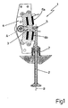
- an electromagnetic actuator 1 controlled by a control system of the present invention is coupled to an intake or exhaust valve 2 of an internal combustion engine and comprises an oscillating arm 3 of ferromagnetic material, having a first end hinged on a fixed support 4 so as to be able to oscillate about a horizontal axis of rotation A perpendicular to a longitudinal axis B of the valve 2, and a second end connected via a hinge 5 to an upper end of the valve 2, an opening electromagnet 6a and a closing electromagnet 6b disposed on opposite sides of the body of the oscillating arm 3 so as to be able to act on command, simultaneously or alternatively, by exerting a net force F on the oscillating arm 3 in order to cause it to rotate about the axis of rotation A and an elastic member 7, adapted to maintain the oscillating arm 3 in a rest position in which it is equidistant from the polar heads of the opening and closing electromagnets 6a and 6b, so as to maintain the valve 2 in an intermediate position
- the opening stroke should be understood as a movement of the valve 2 from the closed position to the position of maximum opening, while the closing stroke should be understood as a full stroke in the opposite direction.
- a control unit 10 comprises a reference generation block 11, a force control block 12, a conversion block 13 and an estimation block 14 and is further interfaced with a guiding and measurement circuit 15.
- the reference generation block 11 receives as input an objective position signal Z T , generated in a known manner by the control unit, and a plurality of parameters indicative of the engine operating conditions (for instance the load L and the number of revolutions RPM).
- the reference generation block 11 also supplies as output a reference position profile Z R and a reference velocity profile V R and supplies them as input to the force control block 12 which also receives a measurement of the actual position Z, supplied by the guiding and measurement circuit 15, and an estimate of the actual velocity V of the valve 2 which is carried out, as described in detail below, by the observation block 14.
- the force control block 12 calculates and supplies as output an objective force value F o indicative of the net force F to be applied to the oscillating arm 3 by means of the electromagnets 6a and 6b in order to minimise the deviations of the actual position Z and of the actual velocity V from the reference position Z R and reference velocity V R profiles respectively.
- the objective force value F o is supplied as input to the conversion block 13 which also receives upper and lower nominal force values F SUP and F INF applied to the oscillating arm 3 by the upper and lower electromagnets 6a and 6b respectively in nominal conditions, and a estimate of disturbing forces ⁇ F.
- the values of the upper and lower nominal forces F SUP and F INF and the estimate of the disturbing forces ⁇ F are supplied by the observation block 14, as will be described in detail below.
- the conversion block 13 supplies as output a pair of upper and lower objective current values I OSUP and I OINF that need to be applied to the upper electromagnet 6a and the lower electromagnet 6b respectively in order to generate the objective force value F o .
- the guiding and measurement circuit 15 receives as input the objective current values I OSUP and I OINF and causes the corresponding upper and lower electromagnets 6a and 6b to be supplied with respective actual currents I SUP and I INF .
- a position sensor 16 of known type adapted to detect the position of the valve 2 or, in an equivalent way, of the oscillating arm 3.
- the position sensor 16 supplies a signal V Z indicative of the actual position Z of the valve 2 to the guiding and measurement circuit 15 which in turn supplies the measurement of the actual position Z and respective measured current values I MSUP and I MINF of the actual currents I SUP and I INF to the control unit 10 and in particular to the observation block 14
- the estimation block 14 calculates and supplies as output an estimate of the actual velocity V, which is supplied to the force control block 12, an estimate of the disturbing forces ⁇ F and the values of the nominal forces F SUP and F INF exerted on the oscillating arm 3 by the upper and lower electromagnets 6a and 6b respectively.
- the estimation block 14 comprises, as shown in Fig, 3, a calculation block 20 which receives as input the measurements of the actual position Z and the measured current values I MSUP and I MINF and supplies as output the values of the nominal forces F SUP and F INF which represent outputs from the estimation block 14.
- the measurement of the actual position Z is also supplied as input to an initialisation block 21 which supplies as output an initialisation signal RS, of logic type, and an initialisation vector X 1 , whose structure will be explained below.
- An observation block 22 receives as input the measurement of the actual position Z, the values of the nominal forces F SUP and F INF and the initialisation vector X 1 .
- An estimate of the state vector X'(t), which represents an output from the observation block 22, is calculated on the basis of these inputs.
- the estimation block 14 further comprises a selector block 23, controlled by the initialisation block 21 by means of the initialisation signal RS.
- the selector block 23 is adapted to connect an input of an extraction block 24 alternatively with the output of the initialisation block 21, when the initialisation signal assumes a first logic value (“TRUE”) or with the output of the observation block 22, when the initialisation signal RS assumes a second logic value (“FALSE").
- the extraction block 24 obtains, from the initialisation vector X 1 or from the estimate of the state vector X'(t), depending on the value assumed by the initialisation signal RS, estimates of the actual velocity V and of the disturbing forces ⁇ F and supplies them as outputs of the estimation block 14.
- the control unit 10 determines the moments of opening and closing of the valve 2. At the same time, it sets the objective position signal Z T to a value representative of the position that the valve 2 should assume.
- the objective position signal Z T is in particular assigned an upper value Z SUP corresponding to the upper contact or a lower value Z INF corresponding to the lower contact, depending on whether the control unit 10 has supplied a command to open or close the valve 2.
- the reference generation block 11 determines the reference position profile Z R and the velocity reference profile V R which respectively represent the position and the velocity which, as a function of time, it is desired to impose on the valve 2 during its displacement between the positions of maximum opening and closure.
- These profiles may for instance be calculated from the objective position signal Z T by means of a two-state non-linear filter, implemented in a known manner by the reference generation block 11, or taken from tables drawn up at the calibration stage.
- the estimation block 14 supplies the values of the upper and lower nominal forces F SUP and F INF , the disturbing forces ⁇ F and the actual velocity V.
- the disturbing forces ⁇ F represent the difference between the objective force value F o and the net force F actually applied to the oscillating arm 3. This difference is due to the variations which, as discussed above, take place with respect to the nominal operating conditions and which have an impact on the movement of the valve 2.
- the calculation block 20 supplies the values of the upper and lower nominal forces F SUP and F INF , as shown in Fig. 3.
- D SUP represents a distance between the polar head of the upper electromagnet 6a and the oscillating arm 3
- ⁇ is a coefficient of proportionality
- I SAT is a saturation current.
- I SUP equal to the saturation current I SAT
- the maximum upper nominal force F SUP that the upper electromagnet 6a is able to exert on the oscillating arm 3 is reached.
- I SUP higher than the saturation current I SAT the upper nominal force F SUP is kept substantially unchanged.
- the coefficient of proportionality ⁇ and the saturation current I SAT depend in a known manner on the distance D SUP and can be obtained by interpolation from respective tables.
- the lower nominal force F INF may be obtained in a completely analogous manner from the equations (1) and (2), in which use should be made of the actual current I INF and a distance D INF between the polar head of the lower electromagnet 6b and the oscillating arm 3 rather than the actual current I SUP and the distance D SUP .
- X(t) and X(t+1) are state vectors of the dynamic system S at the current sampling moment t and at the successive sampling moment t+1;
- U(t) is an input representative of the total nominal force F T given by the sum of the upper and lower nominal forces F SUP and F INF ;
- Y(t) is an output representing the actual position Z;
- A is a transition matrix;
- B is an input matrix and C is an output matrix.
- X 1 , X 2 , X 3 and X 4 are state variables of the dynamic system S corresponding respectively to the actual position Z, the actual velocity V, the disturbing forces ⁇ F and the variations of the disturbing forces ⁇ F, K is an elastic constant, R is a viscous constant, M is an equivalent total mass and ⁇ t is a sampling interval.
- X'(t) and X'(t+1) are estimates of the state vectors X(t) at the moment t and, respectively, X(t+1) at the successive moment t+1
- Y'(t) is an estimate of the output Y(t)
- U'(t) is an input vector of the observer S'.
- the input vector U't is a column vector having the input U(t) as the first member and the output Y(t) as the second member.
- the estimate of the state vector X'(t) supplied by the observer S' coincides with the state vector X(t) of the dynamic system S and, consequently, the elements X' 2 (t) and X' 3 (t) represent estimates of the actual velocity V and of the disturbing forces ⁇ F at the time t respectively.
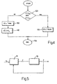
- the initialisation block 21 carries out an initialisation procedure that will be described below, with reference to Fig. 4.
- a test is carried out to check whether the valve 2 is in a free section of stroke, assessing whether the actual position Z is strictly between the upper contact Z SUP and the lower contact Z INF (block 100). If this condition is satisfied (output YES from the block 100), the initialisation signal RS is assigned the logic value "FALSE" (block 110) and the procedure is concluded (block 120).
- X 1 " and X 2 " are state variables of the reduced dynamic system S" calculated at the moment t and at the successive moment t+1 and corresponding to the actual position Z and the actual velocity V respectively;
- U"(t) is an input representing the net force F and
- Y"(t) is an output of the reduced dynamic system S" represented by the actual position Z.
- the force control block 12 therefore carries out, with respect to the reduced dynamic system S", the function of a feedback controller, shown by 31 in Fig. 5, which uses the net force F as the control variable in order to impose that the controlled variable, i.e. the actual position Z, has a course that is as close as possible to a predetermined course given by the reference position profile Z R .
- the objective force value F o calculated by the force control block 12 and the values of the upper and lower nominal forces F SUP and F INF are used by the conversion block 13 to determine, according to a control procedure known as "switching", that will be explained below with reference to Fig. 6, the objective current values I OSUP and I OINF of the respective currents I SUP and I INF that need to be supplied to the upper and lower electromagnets 6a and 6b.
- switching a control procedure known as "switching”
- an actual force value F E that it is necessary to supply in order to exert on the oscillating arm 3 a net force F of a value equal to the objective force value F o is calculated.
- the implementation of the actual force F E is then controlled. A test is therefore carried out in which the actual force F E and the upper nominal force F SUP are compared (block 210).
- an actuation current value I ON is calculated (block 215) and the upper objective current value I OSUP is set to this actuation value I ON (block 220). If not (output NO from the block 210), an exclusion current value I OFF is calculated (block 225) and the upper objective current value I OSUP is set to this exclusion value I OFF (block 230).
- the actuation value I ON and the exclusion value I OFF are calculated as a function of the distance between the polar heads of the electromagnets 6a and 6b and the oscillating arm 3 as explained below.
- a test is then carried out to check whether the actual force F E is lower than the lower nominal force F INF (block 240). If so (output YES from the block 240), an actuation current value I ON is calculated (block 245) and the lower objective current value I OINF is set to this actuation value I ON (block 250). Otherwise (output NO from the block 240), an exclusion current value I OFF is calculated (block 255) and the lower objective current value I OINF is set to this exclusion value I OFF (block 260).
- the procedure is then terminated (block 270).
- the distance D SUP is shown on the abscissa and the curve of the actuation current values I ON is shown by a continuous line, while the exclusion current values I OFF are shown in dashed lines.
- the actuation current I ON is close to the saturation current I SAT ; as the distance D SUP increases the actuation current I ON firstly moves away from the saturation current I SAT , then decreases until it becomes substantially zero beyond a distance D MAX
- the exclusion current I OFF is maximum when the distance D SUP is zero and gradually decreases until it is cancelled out, without ever exceeding the actuation current I ON .
- the actuation and exclusion current values I ON and I OFF my be taken from tables.
- both the upper and lower electromagnets 6a and 6b can be supplied during a same closing or opening stroke of the valve 2, to enable the net force F exerted on the oscillating arm 3 to have a value equal to the objective force value F o .
- the force control block 12 can generate an objective force value F o such as to exert a braking action on this valve 2.
- This braking action is thus obtained by de-activating the upper electromagnet 6a and supplying the lower electromagnet 6b while the valve 2 is still moving towards the upper contact Z SUP .
- the upper electromagnet 6a is used to brake the valve 2, while the lower electromagnet 6b makes it possible to accelerate the valve 2.
- the stages of supply and de-activation of the electromagnets 6a and 6b in order to accelerate or brake the valve 2 as described above are repeated in sequence several times during each opening and closing stroke, preferably with a frequency of some 20 kHz, so as to minimise the deviations of the actual position Z and the actual velocity V of the valve 2 from the reference position profile Z R and the reference velocity profile V R respectively.
- the use of the estimate of force disturbances ⁇ F makes it possible to impose a robust control and to reduce its sensitivity to unforeseeable variations of the operating conditions, such as those already described and brought about by heat gradients, to different pressure conditions of the gases within the combustion chamber, or caused by wear.
- the estimate of the disturbing forces ⁇ F makes it possible simply to take account of the overall effect of all the disturbances acting on the valve 2. Consequently, it is possible to cause the valves accurately to follow desired position and velocity courses, and to moderate velocity at the end-of-stroke sections, so that the contact between the valves and the fixed members takes place gently. This makes it possible to obtain a so-called "soft touch", avoiding impacts that would substantially reduce the life of the valves and would make the use of electromagnetic actuation systems problematic for mass-produced vehicles.
- the estimate of the actual velocity V which is a key parameter for the efficacy of the control, is carried out by means of the observer S'. In this way, this estimate is extremely accurate and has a very low sensitivity to disturbances.
- the proposed method advantageously makes it possible to reduce current consumption and substantially to improve the overall performance of the drive unit. As a result of the lower current absorption, moreover, there is less risk of damage to the windings of the electromagnets as a result of overheating.
- an actuator 45 cooperates with an intake or exhaust valve 46 and comprises an anchor of ferromagnetic material 47 joined rigidly to a stem 48 of the valve 46 and disposed perpendicular to its longitudinal axis C, a pair of electromagnets 49a and 49b at least partially bounding the stem 48 of the valve 46 and disposed on opposite sides with respect to the anchor 47, so as to be able to act, on command, alternatively or simultaneously, by exerting a net force F on the anchor 47 in order to cause it to move in translation parallel to the longitudinal axis C and an elastic member 50 adapted to maintain the anchor 47 in a rest position in which it is equidistant from the polar heads of the two electromagnets 49a and 49b so as to maintain the valve 46 in an intermediate position between the closed position (upper contact) and the position of maximum opening (lower contact) that the valve 46 assumes when
Description
- The present invention relates to a method for the control of electromagnetic actuators for the actuation of intake and exhaust valves in internal combustion engines.
- As is known, drive units are currently being tested in which the actuation of the intake and exhaust valves is managed by using actuators of electromagnetic type that replace purely mechanical distribution systems (camshafts). While conventional distribution systems make it necessary to define a valve lift profile that represents an acceptable compromise between all the possible operating conditions of the engine, the use of an electromagnetically controlled distribution system makes it possible to vary the phasing as a function of the engine point in order to obtain an optimum performance in any operating condition.
- The increase in efficiency and the actual savings resulting from the use of actuators of electromagnetic type are closely linked to the systems and methods used for the control of these actuators.
- According to known methods, based for instance on open loop control systems, when each valve is opened or closed, the corresponding actuators are supplied with currents and/or voltages of a value such as to ensure that the valve, irrespective of the resistance opposing it, reaches the desired position within a predetermined time interval.
- These methods have some drawbacks.
- In the first place, the valves are subject to impacts each time that they come into contact with fixed members in the position of maximum opening (lower contact) or in the closed position (upper contact). This is particularly critical, since the valves are subject to an extremely high number of opening and closing cycles and therefore wear very rapidly.
- The fact that the electrical power supplied must always be sufficient to overcome the maximum resistance that the valve may encounter, even though the operating conditions are such that the actual resistance opposing the valve is lower, is also a drawback. In this way, the overall efficiency of the drive unit is reduced as a result of the waste of electrical power.
- It is also particularly important that a robust control is implemented so as to enable the intake and exhaust valves to be actuated according to desired movement and timing profiles, irrespective of the disturbances that take place and cause the actual operating conditions to deviate from the nominal conditions. The occurrence of a wide range of phenomena may make the actual operating conditions extremely variable.
- For instance, engine temperature variations cause expansions and contractions of materials, as a result of which the friction encountered by the valves may change. Moreover, since the force applied to the ferromagnetic members on which the electromagnets act depends in a highly non-linear manner on the distance between these ferromagnetic members and the polar heads, it will be appreciated that the volume variations caused by heat gradients may have an adverse effect on the control. Further disturbances are due to the fact that the resistance encountered by the valves also depends on the pressure in the combustion chamber which varies depending, for instance, on the torque and power requirement of the consumer and on the engine control strategies implemented.
- DE-A-197 59 840 discloses a method for the control of electromagnetic actuators for the actuation of intake and exhaust valves in internal combustion engines as defined in the preamble of
claim 1. - The object of the present invention is to provide a method for the control of electromagnetic actuators that is free from the above-described drawbacks and, in particular, has a reduced sensitivity to disturbances, making it possible to improve the overall efficiency of the drive unit.
- The present invention therefore relates to a method for the control of electromagnetic actuators for the actuation of intake and exhaust valves in internal combustion engines, in which an actuator, connected to a control unit, is coupled to a respective valve and comprises a moving member actuated magnetically, by means of a net force, in order to control the movement of the valve between a closed position and a position of maximum opening and an elastic member adapted to maintain the valve in a rest position, which method comprises the stages of
- detecting an actual position Z and an actual velocity V of the valve;
- determining a reference position ZR and a reference velocity VR of this valve;
- estimating disturbing forces acting on the valve ; characterised in that it comprises the stages of :
- determining by a feedback control action, an objective force value of this net force to be exerted on the moving ferromagnetic member as a function of the reference position ZR the actual position Z, the reference velocity VR and the actual velocity V in order to minimise differences between the actual position Z and the reference position ZR and between the actual velocity V and the reference velocity VR.
- calculating an actual force as a function of the objective force value and these disturbing forces,
- implementing this actual force value FE.
- The invention is set out in further detail below with reference to a non-limiting embodiment thereof, given purely by way of non-limiting example, and made with reference to the accompanying drawings, in which:
- Fig. 1 is a lateral elevation, partly in cross-section, of a first type of intake or exhaust valve and of the corresponding electromagnetic actuator;
- Fig. 2 is a simplified block diagram relating to the control method of the present invention;
- Fig. 3 is a detailed block diagram of a detail of the block diagram of Fig. 2; Fig. 4 is a first flow diagram with respect to the present method;
- Fig. 5 is a simplified block diagram of a feedback-based dynamic system, implementing the present method;
- Fig. 6 is a second flow diagram with respect to the present method;
- Fig. 7 is a graph relating to current values calculated in accordance with the present method;
- Fig. 8 is a lateral elevation, partly in cross-section, of a second type of intake or exhaust valve and of the corresponding electromagnetic actuator.
- In Fig. 1, an
electromagnetic actuator 1, controlled by a control system of the present invention, is coupled to an intake orexhaust valve 2 of an internal combustion engine and comprises anoscillating arm 3 of ferromagnetic material, having a first end hinged on afixed support 4 so as to be able to oscillate about a horizontal axis of rotation A perpendicular to a longitudinal axis B of thevalve 2, and a second end connected via ahinge 5 to an upper end of thevalve 2, anopening electromagnet 6a and aclosing electromagnet 6b disposed on opposite sides of the body of the oscillatingarm 3 so as to be able to act on command, simultaneously or alternatively, by exerting a net force F on the oscillatingarm 3 in order to cause it to rotate about the axis of rotation A and an elastic member 7, adapted to maintain the oscillatingarm 3 in a rest position in which it is equidistant from the polar heads of the opening and closingelectromagnets valve 2 in an intermediate position between the closed position (upper contact, ZSUP) and the position of maximum opening (lower contact, ZINF) which thevalve 2 assumes when the oscillatingarm 3 is disposed in contact with the polar head of theopening electromagnet 6a and with the polar head of theclosing electromagnet 6b respectively. - For simplicity, reference will be made in the following description to a single valve-actuator unit and, moreover, the opening and
closing electromagnets - Reference will always be made to the position of the
valve 2 in a direction parallel to the longitudinal axis B, with respect to the rest position which is taken as the starting position; the opening stroke should be understood as a movement of thevalve 2 from the closed position to the position of maximum opening, while the closing stroke should be understood as a full stroke in the opposite direction. - All the forces that will be discussed below will, moreover, be considered to be positive when they act in such a way as to close the
valve 2 and negative when they tend to open it - As shown in Fig. 2, a
control unit 10 comprises areference generation block 11, aforce control block 12, aconversion block 13 and anestimation block 14 and is further interfaced with a guiding andmeasurement circuit 15. - The
reference generation block 11 receives as input an objective position signal ZT, generated in a known manner by the control unit, and a plurality of parameters indicative of the engine operating conditions (for instance the load L and the number of revolutions RPM). - The
reference generation block 11 also supplies as output a reference position profile ZR and a reference velocity profile VR and supplies them as input to theforce control block 12 which also receives a measurement of the actual position Z, supplied by the guiding andmeasurement circuit 15, and an estimate of the actual velocity V of thevalve 2 which is carried out, as described in detail below, by theobservation block 14. - The
force control block 12 calculates and supplies as output an objective force value Fo indicative of the net force F to be applied to the oscillatingarm 3 by means of theelectromagnets - The objective force value Fo is supplied as input to the
conversion block 13 which also receives upper and lower nominal force values FSUP and FINF applied to the oscillatingarm 3 by the upper andlower electromagnets observation block 14, as will be described in detail below. - The
conversion block 13 supplies as output a pair of upper and lower objective current values IOSUP and IOINF that need to be applied to theupper electromagnet 6a and thelower electromagnet 6b respectively in order to generate the objective force value Fo. - The guiding and
measurement circuit 15, of known type, receives as input the objective current values IOSUP and IOINF and causes the corresponding upper andlower electromagnets - It is connected, moreover, to a
position sensor 16 of known type adapted to detect the position of thevalve 2 or, in an equivalent way, of the oscillatingarm 3. Theposition sensor 16 supplies a signal VZ indicative of the actual position Z of thevalve 2 to the guiding andmeasurement circuit 15 which in turn supplies the measurement of the actual position Z and respective measured current values IMSUP and IMINF of the actual currents ISUP and IINF to thecontrol unit 10 and in particular to theobservation block 14 - On the basis of the measurements of the actual position Z and the measured current values IMSUP and IMINF and according to methods described in detail below, the
estimation block 14 calculates and supplies as output an estimate of the actual velocity V, which is supplied to theforce control block 12, an estimate of the disturbing forces ΔF and the values of the nominal forces FSUP and FINF exerted on the oscillatingarm 3 by the upper andlower electromagnets - In more detail, the
estimation block 14 comprises, as shown in Fig, 3, acalculation block 20 which receives as input the measurements of the actual position Z and the measured current values IMSUP and IMINF and supplies as output the values of the nominal forces FSUP and FINF which represent outputs from theestimation block 14. - The measurement of the actual position Z is also supplied as input to an
initialisation block 21 which supplies as output an initialisation signal RS, of logic type, and an initialisation vector X1, whose structure will be explained below. - An
observation block 22 receives as input the measurement of the actual position Z, the values of the nominal forces FSUP and FINF and the initialisation vector X1. An estimate of the state vector X'(t), which represents an output from theobservation block 22, is calculated on the basis of these inputs. - The
estimation block 14 further comprises aselector block 23, controlled by theinitialisation block 21 by means of the initialisation signal RS. In particular, theselector block 23 is adapted to connect an input of anextraction block 24 alternatively with the output of theinitialisation block 21, when the initialisation signal assumes a first logic value ("TRUE") or with the output of theobservation block 22, when the initialisation signal RS assumes a second logic value ("FALSE"). - The
extraction block 24 obtains, from the initialisation vector X1 or from the estimate of the state vector X'(t), depending on the value assumed by the initialisation signal RS, estimates of the actual velocity V and of the disturbing forces ΔF and supplies them as outputs of theestimation block 14. - During operation of the engine, the
control unit 10, using known strategies, determines the moments of opening and closing of thevalve 2. At the same time, it sets the objective position signal ZT to a value representative of the position that thevalve 2 should assume. The objective position signal ZT is in particular assigned an upper value ZSUP corresponding to the upper contact or a lower value ZINF corresponding to the lower contact, depending on whether thecontrol unit 10 has supplied a command to open or close thevalve 2. - On the basis of the values of the objective position signal ZT, the load L and the number of revolutions RPM, the
reference generation block 11 determines the reference position profile ZR and the velocity reference profile VR which respectively represent the position and the velocity which, as a function of time, it is desired to impose on thevalve 2 during its displacement between the positions of maximum opening and closure. These profiles may for instance be calculated from the objective position signal ZT by means of a two-state non-linear filter, implemented in a known manner by thereference generation block 11, or taken from tables drawn up at the calibration stage. - At the same time, the
estimation block 14 supplies the values of the upper and lower nominal forces FSUP and FINF, the disturbing forces ΔF and the actual velocity V. The disturbing forces ΔF represent the difference between the objective force value Fo and the net force F actually applied to the oscillatingarm 3. This difference is due to the variations which, as discussed above, take place with respect to the nominal operating conditions and which have an impact on the movement of thevalve 2. - In detail, the
calculation block 20 supplies the values of the upper and lower nominal forces FSUP and FINF, as shown in Fig. 3. With reference, for simplicity, solely to theupper electromagnet 6a, the value of the upper nominal force FSUP is calculated on the basis of the following equations:

- In equations (1) and (2), DSUP represents a distance between the polar head of the
upper electromagnet 6a and theoscillating arm 3, α is a coefficient of proportionality and ISAT is a saturation current. In particular, when an actual current ISUPequal to the saturation current ISAT is supplied to theupper electromagnet 6a, the maximum upper nominal force FSUP that theupper electromagnet 6a is able to exert on theoscillating arm 3 is reached. For actual current values ISUP higher than the saturation current ISAT, the upper nominal force FSUP is kept substantially unchanged. The coefficient of proportionality α and the saturation current ISAT depend in a known manner on the distance DSUP and can be obtained by interpolation from respective tables. The lower nominal force FINF may be obtained in a completely analogous manner from the equations (1) and (2), in which use should be made of the actual current IINF and a distance DINF between the polar head of thelower electromagnet 6b and theoscillating arm 3 rather than the actual current ISUP and the distance DSUP. - As regards the estimates of the actual velocity V and the disturbing forces ΔF carried out by the
observation block 22, the method is based on a discrete-time dynamic system S described by the following matricial equations:

in which t is an integer representing a generic moment of current sampling and t+1 is a sampling moment following immediately thereafter. - Showing the vectors X(t+1) and X(t) and the matrices A, B and C in detail, equations (3) and (4) are respectively equivalent to the equations:


- In particular, in equations (3) to (6), X(t) and X(t+1) are state vectors of the dynamic system S at the current sampling moment t and at the successive sampling moment t+1; U(t) is an input representative of the total nominal force FT given by the sum of the upper and lower nominal forces FSUP and FINF; Y(t) is an output representing the actual position Z; A is a transition matrix; B is an input matrix and C is an output matrix. Moreover, X1, X2, X3 and X4 are state variables of the dynamic system S corresponding respectively to the actual position Z, the actual velocity V, the disturbing forces ΔF and the variations of the disturbing forces ΔF, K is an elastic constant, R is a viscous constant, M is an equivalent total mass and Δt is a sampling interval.
- As will be appreciated by a person skilled in the art, the dynamic system S, as a result of the structure of the transition and output matrices A and C, can be fully observed and it is therefore possible to estimate the state vector X(t+1) from the output Y(t) and from the input U(t) by means of an observer S' described by the following matricial equations:


- In equations (7) and (8), X'(t) and X'(t+1) are estimates of the state vectors X(t) at the moment t and, respectively, X(t+1) at the successive moment t+1, Y'(t) is an estimate of the output Y(t) and U'(t) is an input vector of the observer S'. In particular, the input vector U't is a column vector having the input U(t) as the first member and the output Y(t) as the second member. Moreover, A' is a transition matrix of the observer S', given by the equation:

in which L is a gain matrix (in this case a column vector with four members) that can be obtained by well-known techniques of pole positioning, in order to ensure that the observer S' converges. The input matrix B' of the observer S' is composed of a first block formed by the matrix of the inputs of the dynamic system S and by a second block formed by the gain matrix L and may be represented by the following equation:
- In operation, the estimate of the state vector X'(t) supplied by the observer S' coincides with the state vector X(t) of the dynamic system S and, consequently, the elements X'2(t) and X'3(t) represent estimates of the actual velocity V and of the disturbing forces ΔF at the time t respectively.
- Moreover, as a unilateral constraint is introduced when the
valve 2 is at the end of its stroke in the closed position or the position of maximum opening, in these conditions the observer S' is not able to provide correct estimates of the state X(t) of the dynamic system S. In order to maintain the coherence of the state X(t) and avoid convergence transients that would compromise the efficacy of the control, theinitialisation block 21 carries out an initialisation procedure that will be described below, with reference to Fig. 4. - In detail, a test is carried out to check whether the
valve 2 is in a free section of stroke, assessing whether the actual position Z is strictly between the upper contact ZSUP and the lower contact ZINF (block 100). If this condition is satisfied (output YES from the block 100), the initialisation signal RS is assigned the logic value "FALSE" (block 110) and the procedure is concluded (block 120). If, however, the actual position Z corresponds to the upper contact ZSUP or the lower contact ZINF (output NO from the block 100), the initialisation signal RS is set to the logic value "TRUE" (block 130) and it is imposed that the estimate of the state vector X'(t) of the observer S' is equal to an initialisation vector X1 (block 140) given by the expression:
The procedure is then terminated (block 120). - The
force control block 12 then uses the reference position profile ZR and velocity reference profile VR, together with the measurement of the actual position Z and the actual velocity V, to determine the objective force value Fo of the net force F that needs to be applied to theoscillating arm 3, according to the following equation:
- In (12), N1, N2, K1 and K2 are gains that can be calculated by applying well-known robust control techniques to a reduced dynamic system S", shown by 30 in Fig. 5, that represents the movement of the
valve 2 and is described by the matricial equations:

- In particular, in the equations (13) and (14), X1" and X2" are state variables of the reduced dynamic system S" calculated at the moment t and at the successive moment t+1 and corresponding to the actual position Z and the actual velocity V respectively; U"(t) is an input representing the net force F and Y"(t) is an output of the reduced dynamic system S" represented by the actual position Z.
- The
force control block 12 therefore carries out, with respect to the reduced dynamic system S", the function of a feedback controller, shown by 31 in Fig. 5, which uses the net force F as the control variable in order to impose that the controlled variable, i.e. the actual position Z, has a course that is as close as possible to a predetermined course given by the reference position profile ZR. - As mentioned above, the objective force value Fo calculated by the
force control block 12 and the values of the upper and lower nominal forces FSUP and FINF are used by theconversion block 13 to determine, according to a control procedure known as "switching", that will be explained below with reference to Fig. 6, the objective current values IOSUP and IOINF of the respective currents ISUP and IINF that need to be supplied to the upper andlower electromagnets valve 2 and negative when they act in such a way as to open it. Consequently, the upper nominal force FSUP is always positive (or possibly zero), the lower nominal force FINF is always negative, and the nominal force F, the objective force Fo and the disturbing forces ΔF may be both positive or negative. - In detail at the beginning of the procedure for determining the objective current values IOSUP and IOINF, an actual force value FE that it is necessary to supply in order to exert on the oscillating arm 3 a net force F of a value equal to the objective force value Fo is calculated. For this purpose, account also has to be taken of the disturbing forces ΔF, subtracting them from the objective force value Fo (block 200). The implementation of the actual force FE is then controlled. A test is therefore carried out in which the actual force FE and the upper nominal force FSUP are compared (block 210). If the actual force FE is greater than the upper nominal force FSUP (output YES from the block 210), an actuation current value ION is calculated (block 215) and the upper objective current value IOSUP is set to this actuation value ION (block 220). If not (output NO from the block 210), an exclusion current value IOFF is calculated (block 225) and the upper objective current value IOSUP is set to this exclusion value IOFF (block 230). The actuation value ION and the exclusion value IOFF are calculated as a function of the distance between the polar heads of the
electromagnets oscillating arm 3 as explained below. - A test is then carried out to check whether the actual force FE is lower than the lower nominal force FINF (block 240). If so (output YES from the block 240), an actuation current value ION is calculated (block 245) and the lower objective current value IOINF is set to this actuation value ION (block 250). Otherwise (output NO from the block 240), an exclusion current value IOFF is calculated (block 255) and the lower objective current value IOINF is set to this exclusion value IOFF (block 260).
- The procedure is then terminated (block 270).
- The dependence of the actuation and exclusion current values ION and IOFF on the distance between the polar heads of the
electromagnets oscillating arm 3 will now be discussed again with reference solely to theupper electromagnet 6a, without entering into superfluous detail. - In the graph of Fig. 7, the distance DSUP is shown on the abscissa and the curve of the actuation current values ION is shown by a continuous line, while the exclusion current values IOFF are shown in dashed lines. For low values of the distance DSUP, the actuation current ION is close to the saturation current ISAT; as the distance DSUP increases the actuation current ION firstly moves away from the saturation current ISAT, then decreases until it becomes substantially zero beyond a distance DMAX The exclusion current IOFF, however, is maximum when the distance DSUP is zero and gradually decreases until it is cancelled out, without ever exceeding the actuation current ION.
- The actuation and exclusion current values ION and IOFF my be taken from tables. In particular, in order to optimise these values, it is possible to use separate tables for each of the upper and
lower electromagnets valve 2. - It should be stressed that both the upper and
lower electromagnets valve 2, to enable the net force F exerted on theoscillating arm 3 to have a value equal to the objective force value Fo. For instance, if during a closing stroke, in which thevalve 2 moves between the position of maximum opening and the closed position, the actual velocity V of thevalve 2 exceeds the reference velocity VR, theforce control block 12 can generate an objective force value Fo such as to exert a braking action on thisvalve 2. This braking action is thus obtained by de-activating theupper electromagnet 6a and supplying thelower electromagnet 6b while thevalve 2 is still moving towards the upper contact ZSUP. Vice versa, during an opening stroke, in which thevalve 2 is moving between the closed position and the position of maximum opening, theupper electromagnet 6a is used to brake thevalve 2, while thelower electromagnet 6b makes it possible to accelerate thevalve 2. - The stages of supply and de-activation of the
electromagnets valve 2 as described above are repeated in sequence several times during each opening and closing stroke, preferably with a frequency of some 20 kHz, so as to minimise the deviations of the actual position Z and the actual velocity V of thevalve 2 from the reference position profile ZR and the reference velocity profile VR respectively. - The method described above has the following advantages.
- In the first place, the use of the estimate of force disturbances ΔF makes it possible to impose a robust control and to reduce its sensitivity to unforeseeable variations of the operating conditions, such as those already described and brought about by heat gradients, to different pressure conditions of the gases within the combustion chamber, or caused by wear. In particular, the estimate of the disturbing forces ΔF makes it possible simply to take account of the overall effect of all the disturbances acting on the
valve 2. Consequently, it is possible to cause the valves accurately to follow desired position and velocity courses, and to moderate velocity at the end-of-stroke sections, so that the contact between the valves and the fixed members takes place gently. This makes it possible to obtain a so-called "soft touch", avoiding impacts that would substantially reduce the life of the valves and would make the use of electromagnetic actuation systems problematic for mass-produced vehicles. - Moreover, the estimate of the actual velocity V, which is a key parameter for the efficacy of the control, is carried out by means of the observer S'. In this way, this estimate is extremely accurate and has a very low sensitivity to disturbances.
- The use of a "switching" control procedure advantageously makes it possible to determine the objective currents IOSUP and IOINF efficiently with a low computational input.
- Further advantages are due to the calculation of the actuation and exclusion current values ION and IOFF according to the curves described. In this way, the electromagnet that is actuated receives high current values if the
oscillating arm 3 is close to its polar head and consequently there is a high speed of response. Moreover, in the above conditions exclusion current values IOFF that are not zero are supplied. This avoids an initial absorption due to parasitic currents and the response time is further improved. If, however, the distance between the polar head of the electromagnet and theoscillating arm 3 is high, it would be necessary to supply extremely high currents even to exert forces of a moderate value having almost no impact. Low or zero actuation current values ION are therefore supplied and the corresponding electromagnet is excluded, advantageously obtaining a substantial saving. - It will therefore be appreciated that the proposed method advantageously makes it possible to reduce current consumption and substantially to improve the overall performance of the drive unit. As a result of the lower current absorption, moreover, there is less risk of damage to the windings of the electromagnets as a result of overheating.
- The proposed method may, moreover, also be used for the control of valve actuator units other than those described with reference to Fig. 1. For instance, as shown in Fig. 8, an
actuator 45 cooperates with an intake orexhaust valve 46 and comprises an anchor offerromagnetic material 47 joined rigidly to astem 48 of thevalve 46 and disposed perpendicular to its longitudinal axis C, a pair ofelectromagnets stem 48 of thevalve 46 and disposed on opposite sides with respect to theanchor 47, so as to be able to act, on command, alternatively or simultaneously, by exerting a net force F on theanchor 47 in order to cause it to move in translation parallel to the longitudinal axis C and anelastic member 50 adapted to maintain theanchor 47 in a rest position in which it is equidistant from the polar heads of the twoelectromagnets valve 46 in an intermediate position between the closed position (upper contact) and the position of maximum opening (lower contact) that thevalve 46 assumes when theanchor 47 is disposed in contact with the polar head of theupper electromagnet 49a and respectively with the polar head of thelower electromagnet 49b. - It will be appreciated that modifications and variations may be made to the above description without departing from the scope of the present invention.
Claims (13)
- A method for the control of electromagnetic actuators for the actuation of intake and exhaust valves in internal combustion engines, in which an actuator (1, 45), connected to a control unit (10), is coupled to a respective valve (2, 46) and comprises a moving member (3, 47) actuated magnetically, by means of a net force (F), in order to control the movement of the valve (2, 46) between a closed position (ZSUP) and a position of maximum opening (ZINF) and an elastic member (7, 50) adapted to maintain the valve (2, 46) in a rest position, which method comprises the stages of:detecting an actual position (Z) and an actual velocity (V) of the valve (2, 46);determining a reference position (ZR) and a reference velocity (VR) of this valve (2, 46);estimating disturbing forces (ΔF) acting on the valve (2, 46);
characterised in that it comprises the stages of:determining, by a feedback control action, an objective force value (Fo) of this net force (F) to be exerted on the moving ferromagnetic member (3, 47) as a function of the reference position (ZR), the actual position (Z), the reference velocity (VR) and the actual velocity (V) in order to minimise differences between the actual position (Z) and the reference position (ZR) and between the actual velocity (V) and the reference velocity (VR),calculating an actual force (FE) as a function of the objective force value (Fo) and these disturbing forces (ΔF),implementing this actual force value (FE). - A method as claimed in claim 1, characterised in that the stage of estimating the disturbing forces comprises the stage of:providing an estimate (X') of a state (X) of a dynamic system (S) by means of an observer (S'), a first state variable (X2) of this dynamic system (S) being formed by these disturbing forces (ΔF).
- A method as claimed in claim 2, characterised in that the stage of providing this estimate (X') comprises the stage of:calculating an estimate (X'(t+1)) at a successive sampling moment ((t+1)) as a function of an estimate (X'(t)) at a current sampling moment ((t)).
- A method as claimed in claim 3, characterised in that the stage of calculating this estimate (X'(t+1)) at this successive sampling moment ((t+1)) comprises the stage of:calculating this estimate (X'(t+1)) at a successive sampling moment ((t+1)) according to matricial equation:

A' being a first transition matrix, B' being a first input matrix and U'(t) being an input vector of the observer (S'). - A method as claimed in claim 4, characterised in that the stage of calculating the estimate (X'(t+1)) according to the matricial equation comprises the stage of:calculating this first transition matrix A' according to the matricial equation:

A being a second transition matrix, C being an output matrix of the dynamic system (S) and L being a gain matrix of the observer (S'). - A method as claimed in any one of the preceding claims, characterised in that the stage of calculating an actual force (FE) comprises the stage of:subtracting the disurrbing forces (ΔF) from the objective force value (Fo).
- A method as claimed in any one of the preceding claims, in which the actuator (1, 45) further comprises at least a first and second electromagnet (6a, 6b, 49a, 49b) disposed on opposite sides with respect to the moving member (3,47) and in which the valve (2, 46) travels an opening stroke when moving from the closed position (ZSUP) to the position of maximum opening (ZINF) and a dosing stroke when moving from the position of maximum opening (ZINF) to the dosed position (ZSUP), which method is characterised in that the stage of implementing the actual force value (FE) comprises the stage of:supplying both the first and the second electromagnets (6a, 6b, 49a, 49b) at least once during each opening and closing stroke of the valve (2, 46).
- A method as claimed in claim 7, characterised in that the stage of supplying both the first and the second electromagnets (6a, 6b, 49a, 49b) at least once follows the stage of:calculating as a function of actual position (Z) and of respective measured current values (IMSUP ,IMINF), a first and a second nominal force value (FSUP, FINF) exerted by the first and second electromagnet (6a, 6b, 49a, 49b) respectively on the moving member (3, 47).
- A method as claimed in claim 7, characterised in that the stage of: supplying both the first and the second electromagnets (6a, 6b, 49a, 49b) at least once comprises the stage of:calculating at least a first and a second objective current value (IOSUP, IOINF) as a function of the objective force valeur (Fo) andsupplying the first and the second electromagnets (6a, 6b, 49a, 49b) with a first and a second current (ISUP, IINF) having values equal to the first and the second objective current values (IOSUP, IOINF) respectively.
- A method as claimed in claim 8, characterised in that the stage of calculating at least a first and a second objective current value (IOSUP, IOINF) comprises the stage of:calculating for each of the first and the second electromagnets (6a, 6b, 49a, 49b) at least one actuation current value (ION) and at least one exclusion current value (IOFF) (215, 225, 245, 255) as a function of respective distances (DSUP, DINF) of the moving member (3, 47) from the first electromagnet (6a, 49a) and from the second electromagnet (6b, 49b).
- A method as claimed in claims 8 and 10, characterised in that the stage of calculating at least a first and a second objective current value (IOSUP, IOINF) further comprises the stages of:setting this first objective current value (IOSUP) to this actuation value (ION) if the actual force (FE) is greater than the first nominal force (FSUP),setting this first objective current value (IOSUP) to this exclusion value (IOFF) if the actual force (FE) is smaller than the first nominal force (FSUP),setting this second objective current value (IOINF) to this actuation value (ION) if the actual force (FE) is smaller than the second nominal force (FINF),setting this second objective current value (IOINF) to this exclusion value (IOFF) if the actual force (FE) is greater than the second nominal force (FINF).
- A method as claimed in claim 1, characterised in that the stage of detecting the actual position (Z) and the actual velocity (V) comprises the stage of:estimating the actual velocity (V).
- A method as claimed in claim 5, in which a second state variable (X2) of the dynamic system (S) is formed by the actual velocity (V), characterised in that the stage of estimating the actual velocity (V) comprises the stages of:providing an estimate (X') of a state (X) of a dynamic system (S),calculating an estiamte ((X'(t+1)) at a successive sampling moment ((t+1)),calculating this estimate (X'(t+1)) at this successive sampling moment ((t+1)) according to the matricial equation:
 calculating the first transition matrix A' according to the matricial equation:
Applications Claiming Priority (2)
| Application Number | Priority Date | Filing Date | Title |
|---|---|---|---|
| IT1999BO000656A IT1311411B1 (en) | 1999-11-30 | 1999-11-30 | METHOD FOR THE CONTROL OF ELECTROMAGNETIC ACTUATORS DRIVING OF INTAKE AND EXHAUST VALVES IN A-MOTORS |
| ITBO990656 | 1999-11-30 |
Publications (4)
| Publication Number | Publication Date |
|---|---|
| EP1106790A2 EP1106790A2 (en) | 2001-06-13 |
| EP1106790A8 EP1106790A8 (en) | 2001-11-14 |
| EP1106790A3 EP1106790A3 (en) | 2002-02-13 |
| EP1106790B1 true EP1106790B1 (en) | 2006-02-22 |
Family
ID=11344385
Family Applications (1)
| Application Number | Title | Priority Date | Filing Date |
|---|---|---|---|
| EP00125597A Expired - Lifetime EP1106790B1 (en) | 1999-11-30 | 2000-11-22 | A method for the control of electromagnetic actuators for the actuation of intake and exhaust valves in internal combustion engines |
Country Status (6)
| Country | Link |
|---|---|
| US (1) | US6332436B1 (en) |
| EP (1) | EP1106790B1 (en) |
| BR (1) | BR0006746A (en) |
| DE (1) | DE60026103T2 (en) |
| ES (1) | ES2257255T3 (en) |
| IT (1) | IT1311411B1 (en) |
Families Citing this family (4)
| Publication number | Priority date | Publication date | Assignee | Title |
|---|---|---|---|---|
| IT1311434B1 (en) * | 1999-12-17 | 2002-03-12 | Magneti Marelli Powertain Spa | METHOD FOR THE CONTROL OF ELECTROMAGNETIC ACTUATORS FOR THE ACTIVATION OF INTAKE AND EXHAUST VALVES IN A-MOTORS |
| ITBO20010390A1 (en) * | 2001-06-19 | 2002-12-19 | Magneti Marelli Spa | METHOD OF CONTROL OF AN ELECTROMAGNETIC ACTUATOR FOR THE CONTROL OF A MOTOR VALVE STARTING FROM A STROKE CONDITION |
| DE102008052255B4 (en) | 2008-10-18 | 2018-08-09 | Volkswagen Ag | Method for driving an electromotive actuator of a gas exchange valve |
| US20140277994A1 (en) * | 2013-03-13 | 2014-09-18 | International Engine Intellectual Property Company, LLC | Sliding mode controller for engine thermal management |
Family Cites Families (6)
| Publication number | Priority date | Publication date | Assignee | Title |
|---|---|---|---|---|
| JP3134724B2 (en) * | 1995-02-15 | 2001-02-13 | トヨタ自動車株式会社 | Valve drive for internal combustion engine |
| DE19739840C2 (en) * | 1997-09-11 | 2002-11-28 | Daimler Chrysler Ag | Method for controlling an electromagnetically actuated actuating device, in particular a valve for internal combustion engines |
| US5991143A (en) * | 1998-04-28 | 1999-11-23 | Siemens Automotive Corporation | Method for controlling velocity of an armature of an electromagnetic actuator |
| US5988123A (en) * | 1998-07-15 | 1999-11-23 | Fuji Oozx, Inc. | Method of controlling an electric valve drive device and a control system therefor |
| DE19843073C1 (en) * | 1998-09-19 | 2000-05-31 | Daimler Chrysler Ag | Method for operating an electromagnetic actuator for operating a gas exchange valve |
| DE19852655B4 (en) * | 1998-11-16 | 2005-05-19 | Daimlerchrysler Ag | Method for operating an electromagnetic actuator for actuating a gas exchange valve |
-
1999
- 1999-11-30 IT IT1999BO000656A patent/IT1311411B1/en active
-
2000
- 2000-11-22 ES ES00125597T patent/ES2257255T3/en not_active Expired - Lifetime
- 2000-11-22 DE DE60026103T patent/DE60026103T2/en not_active Expired - Fee Related
- 2000-11-22 EP EP00125597A patent/EP1106790B1/en not_active Expired - Lifetime
- 2000-11-28 BR BR0006746-6A patent/BR0006746A/en not_active IP Right Cessation
- 2000-11-28 US US09/722,714 patent/US6332436B1/en not_active Expired - Fee Related
Also Published As
| Publication number | Publication date |
|---|---|
| ITBO990656A0 (en) | 1999-11-30 |
| US6332436B1 (en) | 2001-12-25 |
| BR0006746A (en) | 2001-12-04 |
| EP1106790A8 (en) | 2001-11-14 |
| DE60026103T2 (en) | 2006-09-28 |
| DE60026103D1 (en) | 2006-04-27 |
| EP1106790A2 (en) | 2001-06-13 |
| EP1106790A3 (en) | 2002-02-13 |
| IT1311411B1 (en) | 2002-03-12 |
| ES2257255T3 (en) | 2006-08-01 |
| ITBO990656A1 (en) | 2001-05-30 |
Similar Documents
| Publication | Publication Date | Title |
|---|---|---|
| US6397797B1 (en) | Method of controlling valve landing in a camless engine | |
| EP1098072B1 (en) | A method for the control of electromagnetic actuators for the actuation of intake and exhaust valves in internal combustion engines | |
| US6390039B2 (en) | Engine valve drive control apparatus and method | |
| US5991143A (en) | Method for controlling velocity of an armature of an electromagnetic actuator | |
| US6681728B2 (en) | Method for controlling an electromechanical actuator for a fuel air charge valve | |
| US6196172B1 (en) | Method for controlling the movement of an armature of an electromagnetic actuator | |
| US6588385B2 (en) | Engine valve drive control apparatus and method | |
| EP1152129B1 (en) | Method and device for estimating the position of an actuator body in an electromagnetic actuator to control a valve of an engine | |
| EP1106790B1 (en) | A method for the control of electromagnetic actuators for the actuation of intake and exhaust valves in internal combustion engines | |
| US7878161B2 (en) | Sliding mode control apparatus and adjusting method | |
| ITBO20000678A1 (en) | METHOD OF CONTROL OF AN ELECTROMAGNETIC ACTUATOR FOR THE CONTROL OF A MOTOR VALVE | |
| EP1162349B1 (en) | Apparatus and method for controlling electromagnetically operable engine valve assembly | |
| JP3614092B2 (en) | Valve clearance estimation device and control device for electromagnetically driven valve | |
| US6340007B2 (en) | Method for estimating the end-of-stroke positions of moving members of electromagnetic actuators for the actuation of intake and exhaust valves in internal combustion engines | |
| EP1152251B1 (en) | Method and device for estimating magnetic flux in an electromagnetic actuator for controlling an engine valve | |
| US6671156B2 (en) | Method for controlling electromagnetic actuators for operating induction and exhaust valves of internal combustion engines | |
| US6920029B2 (en) | Control method for an electromagnetic actuator for the control of a valve of an engine from an abutment condition | |
| ITBO20010760A1 (en) | METHOD FOR ESTIMATING THE POSITION AND SPEED OF AN ACTUATOR BODY IN AN ELECTROMAGNETIC ACTUATOR FOR THE CONTROL OF A VALVE |
Legal Events
| Date | Code | Title | Description |
|---|---|---|---|
| PUAI | Public reference made under article 153(3) epc to a published international application that has entered the european phase |
Free format text: ORIGINAL CODE: 0009012 |
|
| AK | Designated contracting states |
Kind code of ref document: A2 Designated state(s): AT BE CH CY DE DK ES FI FR GB GR IE IT LI LU MC NL PT SE TR Kind code of ref document: A2 Designated state(s): DE ES FR GB SE |
|
| AX | Request for extension of the european patent |
Free format text: AL;LT;LV;MK;RO;SI |
|
| PUAL | Search report despatched |
Free format text: ORIGINAL CODE: 0009013 |
|
| AX | Request for extension of the european patent |
Free format text: AL;LT;LV;MK;RO;SI |
|
| 17P | Request for examination filed |
Effective date: 20020716 |
|
| R17P | Request for examination filed (corrected) |
Effective date: 20020616 |
|
| AKX | Designation fees paid |
Free format text: DE ES FR GB SE |
|
| 17Q | First examination report despatched |
Effective date: 20050224 |
|
| GRAP | Despatch of communication of intention to grant a patent |
Free format text: ORIGINAL CODE: EPIDOSNIGR1 |
|
| GRAS | Grant fee paid |
Free format text: ORIGINAL CODE: EPIDOSNIGR3 |
|
| RAP1 | Party data changed (applicant data changed or rights of an application transferred) |
Owner name: MAGNETI MARELLI POWERTRAIN S.P.A. |
|
| GRAA | (expected) grant |
Free format text: ORIGINAL CODE: 0009210 |
|
| AK | Designated contracting states |
Kind code of ref document: B1 Designated state(s): DE ES FR GB SE |
|
| REG | Reference to a national code |
Ref country code: GB Ref legal event code: FG4D |
|
| REF | Corresponds to: |
Ref document number: 60026103 Country of ref document: DE Date of ref document: 20060427 Kind code of ref document: P |
|
| REG | Reference to a national code |
Ref country code: SE Ref legal event code: TRGR |
|
| REG | Reference to a national code |
Ref country code: ES Ref legal event code: FG2A Ref document number: 2257255 Country of ref document: ES Kind code of ref document: T3 |
|
| ET | Fr: translation filed | ||
| PLBE | No opposition filed within time limit |
Free format text: ORIGINAL CODE: 0009261 |
|
| STAA | Information on the status of an ep patent application or granted ep patent |
Free format text: STATUS: NO OPPOSITION FILED WITHIN TIME LIMIT |
|
| 26N | No opposition filed |
Effective date: 20061123 |
|
| PGFP | Annual fee paid to national office [announced via postgrant information from national office to epo] |
Ref country code: FR Payment date: 20080912 Year of fee payment: 9 |
|
| PGFP | Annual fee paid to national office [announced via postgrant information from national office to epo] |
Ref country code: DE Payment date: 20081127 Year of fee payment: 9 |
|
| PGFP | Annual fee paid to national office [announced via postgrant information from national office to epo] |
Ref country code: ES Payment date: 20081128 Year of fee payment: 9 |
|
| PGFP | Annual fee paid to national office [announced via postgrant information from national office to epo] |
Ref country code: SE Payment date: 20081112 Year of fee payment: 9 |
|
| PGFP | Annual fee paid to national office [announced via postgrant information from national office to epo] |
Ref country code: GB Payment date: 20081117 Year of fee payment: 9 |
|
| EUG | Se: european patent has lapsed | ||
| GBPC | Gb: european patent ceased through non-payment of renewal fee |
Effective date: 20091122 |
|
| REG | Reference to a national code |
Ref country code: FR Ref legal event code: ST Effective date: 20100730 |
|
| PG25 | Lapsed in a contracting state [announced via postgrant information from national office to epo] |
Ref country code: FR Free format text: LAPSE BECAUSE OF NON-PAYMENT OF DUE FEES Effective date: 20091130 |
|
| PG25 | Lapsed in a contracting state [announced via postgrant information from national office to epo] |
Ref country code: DE Free format text: LAPSE BECAUSE OF NON-PAYMENT OF DUE FEES Effective date: 20100601 |
|
| PG25 | Lapsed in a contracting state [announced via postgrant information from national office to epo] |
Ref country code: GB Free format text: LAPSE BECAUSE OF NON-PAYMENT OF DUE FEES Effective date: 20091122 |
|
| REG | Reference to a national code |
Ref country code: ES Ref legal event code: FD2A Effective date: 20110329 |
|
| PG25 | Lapsed in a contracting state [announced via postgrant information from national office to epo] |
Ref country code: SE Free format text: LAPSE BECAUSE OF NON-PAYMENT OF DUE FEES Effective date: 20091123 |
|
| PG25 | Lapsed in a contracting state [announced via postgrant information from national office to epo] |
Ref country code: ES Free format text: LAPSE BECAUSE OF NON-PAYMENT OF DUE FEES Effective date: 20110316 |
|
| PG25 | Lapsed in a contracting state [announced via postgrant information from national office to epo] |
Ref country code: ES Free format text: LAPSE BECAUSE OF NON-PAYMENT OF DUE FEES Effective date: 20091123 |