Technical Field
The present invention relates to an electrochemical
device for moving particles covered with a protein, such as
a microorganism and a blood cell component.
Background Art
Numerous improvements have been carried out
conventionally for detection of a microorganism. The most
important improvement is the enhancement of detection
sensitivity. However, a difference is still present
between the concentration at which harm to the human being
by a microorganism is recognized and detection sensitivity;
and further enhancement of detection sensitivity is
required. Toward this, methods for enhancing detection
sensitivity by condensing the concentration of a
microorganism in a test liquid for example have been
examined. Among these methods, the most prevalent method
is a method of condensing the concentration of a
microorganism by filtration and re-dispersion.
However, there are some microorganisms which are
adsorbed by a filtering material and do not re-extracted at
the time of re-dispersion, and this causes a problem of
being difficult to quantitatively determine these
microorganisms. In addition, in the above-mentioned
technical field, it is desired to have a technology for
condensing the concentration of a microorganism at higher
quantitative in a period shorter than the proliferation
time of the microorganism by simple procedure at low cost.
Furthermore, regarding the waste treatment of a material,
which is used at the time of condensation, it is also
desired to have the material being low in cost, easy to use
and hard to pollute environment at the time of wasting.
Furthermore, numerous improvements have been carried
out conventionally for the removal of microorganisms
(bacteria removal) included in a blood sample, and a method
called disinfection using a drug has been adopted for this
bacteria removal in general.
However, blood itself is a liquid including much
nourishment and functions as a medium for microorganisms;
the disinfection method therefore causes various problems.
For example, there is a limitation in the rate of
disinfection, and the use of the drug may cause a harmful
side effect. Regarding the harmful side effect of the drug
in particular, if each bacteria gains resistance against a
disinfectant, hospital-spread infection and the like may
occur via blood, and this arises the need for development
of a newer disinfectant. In other words, the development
of a disinfectant must be repeatedly competed with the
gaining of the resistance against the disinfectant by
bacteria, resulting in a social problem of today.
Then, a simple physical disinfection method is
desired, considering that the disinfectants for chemically
removing bacteria should not be used daily and that the
disinfectant should only be used strictly as the last means.
Furthermore, it is desired that the materials and the like
used for bacteria removal should be able to be waste-treated
easily at low cost and should be hard to pollute
environment at the time of wasting.
In addition, in an electric appliance, such as an air
conditioner, numerous examinations have been carried out
for the microorganisms included in the air discharged into
a room. Various ideas have been proposed and embodied, in
which, for example, a filter is provided in the airflow
passage of the air conditioner to capture microorganisms
included in the air, and an antimicrobial agent is disposed
on the surface of the filter to restrict the activity of
the captured microorganisms.
However, inorganic and organic components evaporating
and dissipating from an organism and suspending organic
components are present in the air together with
microorganisms, and these may become nourishment sources
for the microorganisms. In other words, when sweat, carbon
dioxide and nitrogen compounds such as ammonia components,
in the air enter the interior of the air conditioner, they
are captured by condensed dew water on the surface of the
heat exchanger in which dew formation occurred. On the
other hand, suspending microorganisms also adhere to the
surface of the heat exchanger in the same manner. Since
the heat exchanger is controlled to operate and stop
repeatedly depending on the ambient temperature, it becomes
wet and dry repeatedly. In addition, while the air
conditioner is repeatedly operated and stopped in a cycle
of one day, the above-mentioned adhered microorganisms may
proliferate by virtue of the captured nourishment sources.
Furthermore, if the dry state of the heat exchanger is
maintained, the affinity of the proliferated microorganisms
to the surface of the heat exchanger may become less, and
they may scatter in the air again.
Furthermore, a refrigerator also has a heat exchanger
in the interior like the air conditioner, and
microorganisms scattered from food accommodated in the
interior adhere to the surface of the heat exchanger. As a
result, the microorganisms multiply depending on the
temperature of the surface of the heat exchanger during the
thawing cycle and the like, and may contaminate the
interior of the refrigerator again. It is therefore
required to reduce the microorganisms on the surface of the
heat exchanger and to keep the surface clean.
As described above, the existence of particles
covered with a protein such as microorganisms and blood
cell components has conventionally been an important factor
in condensing a solution to be detected, in adjusting a
blood component and in removing bacteria from air
conditioners.
Accordingly, the present invention is intended to
provide an electrochemical device capable of moving such
particles by using a simple method.
More particularly, the present invention is intended
to provide a microorganism concentration condensing device
capable of condensing the concentration of a microorganism
in a test liquid including the microorganism, a bacteria
removal device, a blood component induction device and a
blood component induction method capable of separating a
blood component from a blood sample and/or capable of
physically removing a microorganism from a blood sample,
and an electric appliance capable of decreasing the
concentration of a microorganism on the surface of a heat
exchanger.
Disclosure of Invention
The present invention relates to an electrochemical
device for moving particles covered with a protein,
characterized in that said device has at least n (n ≧ 2)
pieces of electrodes contacting with a liquid containing
particles covered with a protein and a circuit generating a
potential difference between the above-mentioned electrodes
in a range such that it does not cause the electrolysis of
the above-mentioned liquid, said device allowing the above-mentioned
particles move by electrophoresis in the aligned
direction of the above-mentioned electrodes.
In this electrochemical device, it is effective that
the above-mentioned circuit is a circuit sweepingly-applies
a voltage in a range such that it does not cause the
electrolysis of the above-mentioned liquid to the above-mentioned
n pieces of electrodes sequentially in a constant
direction, and moves the above-mentioned particles by
electrophoresis in the above-mentioned direction.
In addition, it is effective that the above-mentioned
particles covered with a protein are microorganisms and/or
blood cell components, and that a liquid having a condensed
concentration of the microorganisms and/or blood cell
components is obtained.
Furthermore, it is effective that the device has a
structure allowing the above-mentioned liquid flow across
the above-mentioned electrodes, and that the direction of
voltage application to the respective electrodes is
perpendicular to the flow direction of the above-mentioned
liquid.
Furthermore, it is effective that the above-mentioned
electrodes are vortex-type electrodes, and that the above-mentioned
electrodes are disposed so as to extend to the
same central point from the outer end portions to the inner
end portions of the above-mentioned electrodes without
overlapping each other.
Furthermore, it is effective that the above-mentioned
electrodes are spiral electrodes, and that the above-mentioned
electrodes are disposed so as to extend from the
upper end portions to the lower end portions of the above-mentioned
electrodes without overlapping each other.
Furthermore, it is effective that the above-mentioned
electrodes are sheet-shaped porous electrodes and that the
device is provided with a wound type electrode, which is
obtained by stacking n (n ≧ 3) pieces of laminates, each
comprising the above-mentioned sheet-shaped porous
electrode and a sheet-shaped porous spacer in the order of
the above-mentioned electrode and spacer and by winding the
stacked laminates.
Furthermore, in the above-mentioned electrochemical
device, it is effective that the above-mentioned n pieces
of electrodes have oxidation/reduction potentials different
from each other, and the above-mentioned circuit is one
short-circuiting the above-mentioned n pieces of electrodes
to move the above-mentioned particles by electrophoresis in
the aligned direction of the above-mentioned electrodes.
In this case, it is effective that the above-mentioned
particles covered with a protein are
microorganisms and/or blood cell components, and that a
liquid having a condensed concentration of the
microorganisms and/or blood cell components is obtained.
Furthermore, it is effective that an introduction
portion and a discharge portion for the above-mentioned
liquid are provided in the vicinity of an electrode having
a higher oxidation/reduction potential, and that a
microorganism discharge portion and/or a microorganism
adsorption portion are provided in the vicinity of an
electrode having a lower oxidation/reduction potential.
Furthermore, it is effective that an electrically
insulating structural member through which the above-mentioned
liquid can move is disposed in the space between
the above-mentioned electrodes.
Furthermore, it is effective that an electrode other
than electrode(s) having the lowest oxidation/reduction
potential has a structure allowing the above-mentioned
liquid to flow into the above-mentioned space.
Furthermore, it is effective that the above-mentioned
structure has a porous, mesh or brush form.
Furthermore, it is effective that an electrode other
than electrode(s) having the lowest oxidation/reduction
potential has the form of a film, through which the
microorganisms and/or blood cell components contained in
the above-mentioned liquid transmit, and is stacked on the
surface of the above-mentioned electrically insulating
structural member.
Brief Description of Drawings
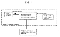
FIG. 1 is a block diagram showing the structure of a
microorganism concentration condensing device in accordance
with the present invention.
FIG. 2 is a view showing a method of sweepingly
applying voltage to respective electrodes using a circuit
in the microorganism concentration condensing device in
accordance with the present invention.
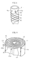
FIG. 3 is a schematic perspective view showing the
structure of the main portion of a microorganism
concentration condensing device comprising vortex-type
electrodes in accordance with the present invention.
FIG. 4 is a partially cutaway schematic perspective
view showing a microorganism concentration condensing
device in accordance with the present invention, in which
plural flat substrates having the vortex-type electrodes
shown in FIG. 3 are stacked.
FIG. 5 is a schematic perspective view showing the
structure of the main portion of a microorganism
concentration condensing device comprising spiral
electrodes in accordance with the present invention.
FIG. 6 is a schematic perspective view showing the
structure of the main portion of a microorganism
concentration condensing device comprising sheet-shaped
porous electrodes in accordance with the present invention.
FIG. 7 is a schematic view showing the structure of a
bacteria removing device comprising a wound type electrode
in accordance with the present invention.
FIG. 8 is a partially cutaway schematic perspective
view showing the wound type electrode of the bacteria
removing device shown in FIG. 7.
FIG. 9 is a schematic perspective view showing a box-shaped
bacteria removing device in accordance with the
present invention.
FIG. 10 is a schematic perspective view showing a
heat exchanger portion in an air conditioner in accordance
with the present invention.
FIG. 11 is a schematic view showing the structure of
a microorganism concentration condensing cell produced in
accordance with embodiment 8 of the present invention.
FIG. 12 is a schematic view showing the structure of
a microorganism concentration condensing device produced in
accordance with the embodiment 8 of the present invention.
FIG. 13 is a view showing the structure of a first-aid
adhesive tape in accordance with an embodiment of a
blood component inducting device of the present invention.
FIG. 14 is a view showing the structure of a sanitary
napkin in accordance with another embodiment of the blood
component inducting device of the present invention.
FIG. 15 is a schematic perspective view showing a
heat exchanger portion in an air conditioner in accordance
with the present invention.
Best Mode for Carrying Out the Invention
The inventors of the present invention paid attention
to the fact that particles covered with a protein such as
microorganisms and blood cell components have certain
charges because of the protein and completed the present
invention. Namely, the present invention relates to an
electrochemical device for moving particles covered with a
protein, comprising at least n (n ≧ 2) pieces of
electrodes contacting with a liquid containing particles
covered with a protein and a circuit generating a potential
difference in a range such that it does not cause the
electrolysis of the above-mentioned liquid between the
above-mentioned electrodes, wherein the above-mentioned
particles are moved by electrophoresis.
The above-mentioned particles covered with a protein
may be contained in the above-mentioned liquid in any state,
such as a dispersion or a suspension. As the above-mentioned
particles, there are exemplified microorganisms
and/or blood cell components. For this reason, a solvent,
an electrolyte and the like may also be contained in the
above-mentioned liquid.
In the case where this electrochemical device is
applied to an electric appliance provided with a heat
exchanger, the present invention provides an electric
appliance provided with a heat exchanger, comprising an
opposed member opposed to the heat exchanger with a space
therebetween and disposed in condensed dew water flowing
from the above-mentioned heat exchanger at a position
contacting with the above-mentioned condensed dew water
together with the surface of the above-mentioned heat
exchanger, in which a microorganism present between the
above-mentioned heat exchanger and the above-mentioned
opposed member is moved in the direction of the above-mentioned
opposed member.
The electrochemical device of the present invention
can be applied further to various devices. In particular,
by changing the type of the electrode and the structure of
the circuit, it is possible to obtain electrochemical
devices, which operates by using mainly two kinds of
mechanisms.
More specifically, the present invention provides a
first electrochemical device comprising plural electrodes
having the same oxidation/reduction potential and a circuit
capable of sweepingly applying a voltage to the plural
electrodes, and a second electrochemical device comprising
plural electrodes having different oxidation/reduction
potentials and a circuit short-circuiting the above-mentioned
plural electrodes. In the second electrochemical
device in particular, the inventors of the present
invention have found that if the plural electrodes having
different oxidation/reduction potentials are employed, the
above-mentioned particles can be moved by simply short-circuiting
the electrodes even without positively applying
a voltage.
Still more specifically, the present invention can be
used as a microorganism concentration condensing device, a
bacteria removing device and a blood component inducting
device having various functions and shapes by appropriately
changing the kind of the above-mentioned particle and
liquid, the number and kind of the electrode and the
configuration of the circuit.
The above-mentioned first electrochemical device and
second electrochemical device will be described below.
(1) With respect to First electrochemical device
(i) Microorganism concentration condensing device
The present invention provides a microorganism
concentration condensing device comprising at least n (n ≧
3) pieces of electrodes contacting with a test liquid
containing a microorganism, a substrate with the above-mentioned
electrodes disposed thereon, and a circuit
sweepingly applying a voltage in a range such that it does
not cause the electrolysis of the above-mentioned test
liquid to the above-mentioned respective electrodes
sequentially in a constant direction to move the
microorganisms in the above-mentioned test liquid by
electrophoresis to obtain a test liquid having a high
microorganism concentration.
In this microorganism concentration condensing device,
it is effective that the above-mentioned electrodes are
vortex-type electrodes, that the above-mentioned substrate
is a flat substrate, and that the above-mentioned
electrodes are disposed on the above-mentioned flat portion
so as to extend to the same central point from the outer
end portions to the inner end portions of the above-mentioned
electrodes without overlapping each other.
Furthermore, it is effective that the above-mentioned
electrodes are spiral electrodes, that the above-mentioned
substrate is a pillar-shaped substrate, and that the above-mentioned
electrodes are disposed on the side of the above-mentioned
pillar-shaped portion so as to extend from the
upper end portions to the lower end portions of the above-mentioned
electrodes without overlapping each other.
Furthermore, it is effective that the above-mentioned
electrodes are sheet-shaped porous electrodes, that the
above-mentioned substrate is a sheet-shaped porous spacer,
that n (n ≧ 3) pieces of laminates, each comprising the
above-mentioned sheet-shaped electrode and the porous
spacer, are stacked in the order of the above-mentioned
electrode and spacer without overlapping at the end
portions of the electrodes of the respective laminates, and
that the laminates are wound.
Furthermore, it is effective that the above-mentioned
circuit performs sweeping application by applying a
positive voltage for microorganism migration to the first
electrode of the above-mentioned n pieces of electrodes,
applying a negative voltage for microorganism migration to
the above-mentioned first electrode at the same time when
applying a positive voltage for microorganism migration to
the second electrode, ······ , applying a negative voltage for
microorganism migration to the (n-1)th to the first
electrodes at the same time when applying a positive
voltage for microorganism migration to the "n"th electrode,
furthermore, applying a negative voltage for microorganism
migration to the "n"th to the second electrodes at the same
time when applying a positive voltage for microorganism
migration to the above-mentioned first electrode, whereby
the microorganism are allowed to migrate from the first
electrode to the "n" th electrode.
Furthermore, it is effective that the above-mentioned
circuit sweepingly applies a voltage to the above-mentioned
electrodes at a rate of 100 µm/sec or less in terms of the
distance of the migration of the microorganism.
A plurality of the above-mentioned substrates having
the electrodes may be provided. In addition, the above-mentioned
electrodes may form paired electrodes.
The above-mentioned microorganism concentration
condensing device comprises at least n (n ≧ 3) pieces of
electrodes contacting with a test liquid containing a
microorganism, a substrate with the above-mentioned
electrodes disposed thereon, and a circuit sweepingly
applying a voltage in a range such that it doe not cause
the electrolysis of the above-mentioned test liquid to the
above-mentioned electrodes sequentially in a constant
direction, whereby the microorganism in the above-mentioned
test liquid is moved on the above-mentioned substrate and a
test liquid having a high microorganism concentration can
be given.
This microorganism concentration condensing device
may be used to detect the concentration of the
microorganism contained in the test liquid, and may be used
for a part of a microorganism concentration measurement
system. Herein, FIG. 1 is a block diagram conceptually
showing the structure of the microorganism concentration
condensing device in accordance with the present invention.
As shown in FIG. 1, the microorganism concentration
condensing device in accordance with the present invention
comprises a test liquid system comprising a test liquid
portion, a condensed test liquid portion and a
microorganism concentration condensing portion, and a
circuit portion for sweepingly applying a voltage to the
electrodes of the microorganism concentration condensing
portion.
The number of the electrodes is not limited in
particular, provided that the number is three or more. In
the followings, the operation principle of the
microorganism concentration condensing device of the
present invention will be described by taking a case in
which the number of the electrodes is three as a typical
example.
In first, a voltage having a level not electrolyzing
the test liquid, particularly an electrolyte contained in
the test liquid, is applied to the electrodes arranged in
accordance with the above-mentioned structure. This
voltage having a level not electrolyzing the test liquid
should be determined depending on the electrode, the
solvent containing a microorganism, the electrolyte and
medium for proliferation and the like.
By applying the voltage as described above, the
negatively charged microorganism can be moved by
electrophoresis without causing deterioration of the test
liquid due to the electrolysis. In other words, by making
one of the electrodes negative and by making the other
positive, the microorganism can be allowed to migrate from
the negative portion to the positive portion. As a result,
it is possible to obtain a test liquid having a condensed
concentration.
The method of the voltage application to each
electrode will be described in more detail. It is
preferable that voltage application is carried out
sequentially at constant intervals in order that the
microorganism is allowed to migrate in a constant direction
along each electrode. It is therefore preferable to apply
a pulse-shaped potential. FIG. 2 is a view showing a
method of sweepingly applying voltage to the respective
electrodes by using a circuit in the concentration
condensing device in accordance with the present invention.
The electrodes are arranged sequentially in the
migration direction of microorganism, a first electrode, a
second electrode and a third electrode; the voltage is
applied to the electrodes in the order of the first
electrode, the second electrode and the third electrode;
hereafter, the voltage is applied again to the first
electrode, the second electrode and the third electrode
sequentially and repeatedly.
The duration of time between voltage application to
one electrode and voltage application to the next electrode,
i.e., the rate of sweeping, differs depending on the
distance between the electrodes, the thickness of the
electrodes, and the like; however, the rate is required to
be substantially less than the rate of the migrating
microorganism. As a result of experiments, the inventors
of the present invention have found that the desired
microorganism can be migrated at a favorably high recovery
rate by setting the sweeping application rate at
substantially 100 µm/sec or less, since the migrating rate
of the microorganism is 100 µm/sec or less in the
microorganism concentration condensing device of the
present invention.
In addition, the microorganism contained in the test
liquid and subjected to condensation can be moved by
electrophoresis when a voltage is applied. For example,
there are Colon bacilli, yellow staphylococci and the like.
Furthermore, as a material for constituting the
electrodes, conventional materials can be used; aluminum
foil, copper foil, a carbon mesh, a foamed metal, carbon
fiber, a carbon mesh, and the like can be exemplified.
Moreover, as a material for constituting the
substrate, insulating materials such as a glass plate, a
glass mat, a polypropylene non-woven fabric and a polyester
non-woven fabric, and the like can be used for example.
A microorganism concentration condensing device in
accordance with a first electrochemical device of the
present invention will be described below more specifically
by using embodiments; however, the present invention is not
limited to these embodiments.
Embodiment 1
FIG. 3 is a schematic perspective view showing the
structure of the main portion of a microorganism
concentration condensing device comprising vortex-type
electrodes in accordance with the present invention. Three
electrodes are used herein. In this embodiment, the above-mentioned
electrodes are vortex-type electrodes, and the
above-mentioned substrate is a flat substrate. Furthermore,
the above-mentioned electrodes are disposed on the above-mentioned
flat substrate so that the electrodes extend to
the same center from the outer end portions to the inner
end portions thereof without overlapping each other.
As shown in FIG. 3, vortex- type electrodes 2, 3 and 4
are disposed on a substrate 1 made of an insulating
material such as a glass plate. This substrate may be
constituted by a porous material, through which a
microorganism can pass. In addition, the substrate should
only have a flat portion on which the vortex-type
electrodes can be disposed, and the shape thereof may be
circular or rectangular.
The electrodes are disposed so that they do not
overlap each other from the outer end portions 2a, 3a and
4a to the inner end portions 2b, 3b and 4b of the
electrodes. In other words, the electrodes are disposed to
have a structure in which the end portions 2a, 3a and 4a of
the electrodes, used as the electrode lead-out ports, are
provided at the peripheral ends of the substrate 1, and the
electrodes are disposed so that they do not make contact
with each other. In addition, the electrodes extend to the
same center (a microorganism exit 5, herein). The
electrodes can be disposed three-dimensionally at positions
opposed to each other, instead of being disposed on the
same plane.
For example, two flat substrates provided with the
above-mentioned vortex-type electrodes are disposed so that
the vortex-type electrodes on the flat substrates are
opposed to each other with a space therebetween, and the
concentration of the microorganism concentration of a test
liquid can be condensed in the space. In other words, the
above-mentioned electrodes may form paired electrodes.
The operation principle of this microorganism
concentration condensing device is described above; the
microorganism can be moved from the outer peripheral
portions of the vortex-type electrodes to the centers of
the vortex-type electrodes by controlling the above-mentioned
sweeping rate for applying a voltage to the
respective electrodes in sequence. Consequently, only the
microorganism in the test liquid can be moved to the
microorganism exit 5; as a result, it is possible to obtain
a test liquid having a condensed microorganism
concentration.
By providing the microorganism exit 5 at the central
portions of the vortex-type electrodes, it is possible to
theoretically obtain a concentration rate equal to the
ratio of the outer periphery and the inner periphery of the
vortex-type electrode, that is, the ratio of the diameter
of the outer periphery and the diameter of the inner
periphery.
In addition, as the result of wholehearted studies,
the inventors of the present invention have found that the
microorganism concentration condensing device in accordance
with the
embodiment 1 should preferably be operated in the
following conditions, for example.
To obtain a higher microorganism condensation effect,
it is also possible to employ a devise an embodiment shown
in FIG. 4. FIG. 4 is a partially cutaway schematic
perspective view showing a microorganism concentration
condensing device in accordance with the present invention,
in which plural flat substrates having the vortex-type
electrodes shown in FIG. 3 are stacked.
In the embodiment shown in FIG. 4, the plural flat
substrates having the vortex-type electrodes shown in FIG.
3 are stacked, and a hollow core member 5' used as an
electrode is provided at the microorganism exit 5 disposed
at the center. The outer peripheries of the substrates are
covered with a cylindrical member 6. In addition, by
providing a groove or a through hole (not shown) in the
hollow core member 5', the microorganism moved by
electrophoresis may be recovered in a container (not shown)
provided below the core member 5', for example.
Furthermore, in order to introduce a test liquid, a
test liquid introduction portion may be constituted by
disposing sheath-shaped member on the outside of the
cylindrical member 6 and by providing a through hole or the
like in the cylindrical member 6 communicating with the
interior thereof, for example. A test liquid introduction
device may be provided separately from the cylindrical
member 6.
In this case, the hollow core member 5' in which the
microorganism gathers should be positively charged, and the
cylindrical member 6 should be negatively charged.
In accordance with this kind of embodiment, in the
above-mentioned microorganism concentration measurement
system, the effects of the microorganism concentration
condensing device of the present invention can be enhanced
further.
Embodiment 2
FIG. 5 is a schematic perspective view showing the
structure of the main portion of a microorganism
concentration condensing device comprising spiral
electrodes in accordance with the present invention. In
the microorganism concentration condensing device in
accordance with this embodiment, the electrodes are spiral
electrodes, and the substrate is a pillar-shaped substrate;
the electrodes are disposed on the side face of the pillar-shaped
portion so that the electrodes do not overlap each
other from the upper end portions to the lower end portions
thereof.
As shown in FIG. 5, three spiral electrodes 8, 9 and
10 are disposed on the side face of a cylindrical substrate
7 from the upper end portions 8a, 9a and 10a to the lower
end portions (not shown) of the electrodes without
overlapping each other. Although the cylindrical substrate
7 is shown as the pillar-shaped substrate, it may be a
prism-shaped substrate, for example. Furthermore, it may
be hollow.
The material for constituting the substrate may be
the same as that mentioned in the above embodiment 1. For
example, the above substrate may be constituted by a porous
material or may be hollow so that the microorganism can
pass through the inside of the substrate.
The spiral electrodes can be disposed three-dimensionally
on concentric circles, not on the same plane.
For example, two hollow cylinders having different
diameters are used as substrates, and a spiral electrode is
provided on the outside face of the cylindrical substrate A
having a smaller diameter. Another spiral electrode is
provided on the inside face of the cylindrical substrate B
having a larger diameter. Furthermore, the cylindrical
substrate A is provided inside the cylindrical substrate B,
with a space formed between the two substrates; in this
space, the condensation of the microorganism concentration
in a test liquid can be performed. In this way, the above
electrodes may form paired electrodes.
In this microorganism concentration condensing device,
by appropriately controlling the above-mentioned sweeping
rate for voltage application as described above, the
microorganism can be moved along the spiral electrodes from
one end to the other end of the pillar-shaped substrate.
Furthermore, by providing a bacteria test liquid
introduction portion (not shown) at one end of the pillar-shaped
substrate and by providing a microorganism exit (not
shown) at the other end, it is possible to attain efficient
microorganism condensation.
Moreover, concrete operation conditions may be the
same as those of the above-mentioned embodiment 1.
Embodiment 3
FIG. 6 is a schematic perspective view showing the
structure of the main portion of a microorganism
concentration condensing device comprising sheet-shaped
porous electrodes in accordance with the present invention.
In the microorganism concentration condensing device in
accordance with this embodiment, the electrodes are sheet-shaped
porous electrodes, and the substrates are sheet-shaped
porous spacers. In addition, n (n ≧ 3) pieces of
laminates, each comprising the above-mentioned electrode
and spacer, are stacked in the order of electrode and
spacer while the end portions of the electrodes in the
laminates do not overlap each other; and the obtained
laminates are wound.
Each of sheet-shaped porous electrodes 11, 12 and 13
has numerous pores through which the microorganism can
transmit, and the electrodes are stacked and wound together
with sheet-shaped porous spacers 14, 15 and 16, each of
which is provided between the electrodes and through which
the microorganism can transmit. In other words, the
electrodes 11, 12 and 13 do not contact with each other,
and each of electrode lead-out ports 11a, 12a and 13a is
provided at one end of the periphery of each electrode.
The operation principle of the microorganism
concentration condensing device in accordance with the
present embodiment is as described above; by appropriately
controlling the above-mentioned sweeping rate for voltage
application to the electrodes, the microorganism can be
moved from the outer peripheries to the center portions of
the sheet-shaped electrodes appeared in vortex.
In this case, by providing a cylindrical member (not
shown) used as a microorganism exit at the central portion
of the vortex, for example, a condensation rate equal to
the ratio of the outer periphery and the inner periphery of
the vortex, that is, the ratio of the diameter of the outer
periphery and the diameter of the inner periphery, can be
obtained' theoretically.
As a material for the sheet-shaped porous electrode
used as the electrode in this case, a copper mesh, a foamed
metal, a carbon mesh and the like can be exemplified.
Furthermore, as a material for the sheet-shaped porous
spacer used as the substrate, a polypropylene non-woven
fabric and a polyester non-woven fabric can be exemplified.
Embodiment 4
It is also possible to obtain a microorganism
concentration condensing device by forming a plurality of
the substrates provided with the electrodes as described in
the above-mentioned embodiment 3, connecting the lead-out
portions 11a, 12a and 13a disposed at the respective
electrodes, and connecting the plural substrates provided
with the electrodes.
By using this kind of structure, it is possible to
increase the amount of a test liquid for treatment, and the
microorganism concentration condensing effect for the
bacteria test liquid can be enhanced further.
By the microorganism concentration condensing device
of the present invention, the condensation of the
microorganism concentration in a test liquid can be carried
out by using fewer process steps, more easily, in a shorter
time, at higher quantitative and more stably, in comparison
with a method in which the condensation of the
microorganism concentration is carried out by filtering and
re-extracting the test liquid containing the microorganism.
Further, in the microorganism concentration
condensing device of the present invention, by
appropriately selecting the materials for the components
thereof, the device can be converted into a disposable type
or a continuous-use type, and therefore has a wide range of
applications.
Furthermore, the device can also be used as a
bacteria removing device for water-purification pipes, food
industry and the like, for example, as another effect
thereof.
(ii) Bacteria removing device
Next, the present invention also provides a bacteria
removing device comprising an inflow port for allowing a
test liquid containing a microorganism to flow into the
device, an inflow guide for guiding the test liquid from
the above-mentioned inflow port to the vicinity of a
positive electrode, at least n (n ≧ 3) pieces of
electrodes contacting with the test liquid flowed in and
having a pore through which the test liquid passes, a
negative electrode disposed to sandwich the n pieces of
electrodes with respect to the positive electrode, a
discharge port for discharging the test liquid having
passed through the n pieces of electrodes, an outflow guide
for guiding the flow of the test liquid to be discharged,
and a circuit for sweepingly applying a voltage in a range
such that it does not cause the electrolysis of the test
liquid to the n pieces of electrodes sequentially in a
constant direction.
In this bacteria removing device, a vortex-type
electrode, which is obtained by winding n pieces of
electrodes and n pieces of mesh-like electrodes while an
insulating layer having pores through which the test liquid
pass being held between the electrodes. It is effective
that the direction of voltage application to the electrodes
is perpendicular to the direction of the flow of the test
liquid containing a microorganism.
Furthermore, it is effective that the n pieces of
electrodes are porous flat electrodes having pores through
which the test liquid can pass, that a structural body
obtained by stacking the units several times, which is
obtained by stacking an insulating layer having pores
through which the test liquid can pass between the
electrodes so as to be held therebetween, and that the
direction of voltage application to the electrodes is set
perpendicular or opposite to the flow direction of the
bacteria liquid to be treated containing a microorganism.
Furthermore, it is effective that the circuit carries
out the sweeping voltage application by: applying a
negative voltage to the first electrode of the n pieces of
electrodes, a positive voltage to the second electrode, and
maintaining the electrodes other than the first and second
electrodes in a no-connection state with voltage applied;
in the next timing, applying a negative voltage to the
second electrode, a positive voltage to the third electrode,
and maintaining the electrodes other than the second and
third electrodes in a no-connection state with no voltage
applied; further in the next timing, by shifting the
voltage application state one by one sequentially in the
same manner as described above.
Furthermore, as the sweeping voltage application
timing of the above-mentioned circuit, it is effective that
the time for the change from the negative voltage
application to the positive voltage application is 100µ
m/sec or less by converting into the time of the distance
between electrodes/sweeping timing (1 cycle time/n).
Furthermore, a plurality of the above-mentioned
electrode structures may be disposed.
Embodiment 5
In a bacteria removing device having a wound type
electrode in accordance with the first electrochemical
device of the present invention, a schematic view showing
the structure of a bacteria removing device in which the
number of the wound type electrodes is three is given in
FIG. 7. Furthermore, a partially cutaway schematic
perspective view showing the wound type electrode 21 of the
bacteria removing device shown in FIG. 7 is given in FIG. 8.
First, a method of producing the bacteria removing
device in accordance with the present invention will be
described. A 30-mesh copper mesh formed of copper wires
having a diameter of 0.22 mm was cut to a size of 10 mm in
width and 30 cm in length, an end portion was treated, and
a process for taking out a lead wire from the end portion
was carried out so as to make three mesh-like electrodes 22.
Next, three mesh-like insulating layers 23, each
formed of a 30-mesh polyester mesh having a thickness of
about 300 µm and a size larger than the above-mentioned
copper mesh by 1 cm in width and length were made.
By alternately stacking the above-mentioned copper
meshes and insulating layers and by winding them around a
core member (not shown) of about 5 mm, a wound structure
having a diameter of about 4 cm was obtained. The same
polyester mesh as that used for the insulating layer was
wound around the surface of this wound structure, and the
same copper mesh as that used for the above-mentioned
electrode was wound around the surface of the wound
structure, whereby the wound type electrode 21 was obtained.
This copper mesh was subjected to the same lead taking out
process as that for the above-mentioned electrode.
This wound type electrode 21 is accommodated in a
cylindrical container 24 for the bacteria removing device
having an inside diameter of about 4.5 cm. This container
24 has a size capable of snugly accommodating the above-mentioned
wound type electrode. The bottom portion has a
flat structure, the central portion is provided with a
washing-out port 25, and the bottom side face is provided
with a treated test liquid discharge port 26. In addition,
the bottom portion is provided with a funnel-shaped outflow
guide 27 so that the test liquid can be discharged without
causing turbulence.
The above-mentioned wound type electrode was disposed
on the outflow guide 27 so as to be mounted thereon, and a
funnel-shaped inflow guide 28 was provided thereon to
smoothen the introduction of the test liquid. A test
liquid inflow port 29 was provided on the side face of the
inflow guide 28, thereby obtaining a structure not allowing
the test liquid to leak at the inflow port and the lower
portions.
After the above-mentioned structure was completed,
the core member was extracted, and a copper wire 30 having
a diameter of about 0.5 mm was inserted into the space
portion for the core member so as to pass through down to
the washing-out port 25. Lead wires 31 were taken out from
the upper portion of the container 24 together with the
copper wire 30 while the lead wires were covered with
sleeves to prevent electrical contact among them. This
completes the main portion of the bacteria removing device.
Next, a circuit for driving the main unit portion of
the bacteria removing device completed as described above
and the operation principle will be described.
The circuit used to drive this bacteria removing
device may be a relay circuit or a semiconductor circuit,
and sequentially repeats a time for connection to the
positive electrode of a power source generating a voltage
of 0.7 V, a time for connection to the negative electrode
thereof and a time for no connection to the power source
circuit in sequence.
The bacteria removing device performs bacteria
removal in a period from the entry of the test liquid into
the test liquid inflow port to the discharge from the test
liquid discharge port. Namely, the bacteria removing
device comprises at least n (n ≧ 3) pieces of electrodes
contacting with the test liquid, a pair of electrodes
comprising a positive electrode at the outermost shell and
a negative electrode at the central portion, disposed to
sandwich these n pieces of electrodes, and a circuit for
sweepingly applying a voltage in a range such that it does
not cause the electrolysis of the above-mentioned test
liquid to the above-mentioned electrodes sequentially in a
constant direction, in which the microorganism in the test
liquid can be transferred to the central portion, and the
microorganism can be discharged from the washing-out port.
This bacteria removing device induces the
microorganism in the test liquid to the stacked electrodes
and sweepingly applies the voltage to the electrodes to
move the microorganism from the vicinity of one electrode
and collect in the vicinity of the other electrode, thereby
discharges the microorganism after restricting the movement
of the microorganism finally. In the meantime, the test
liquid containing the microorganism supplied to the present
device is microorganism-removed.
A structure having three wound electrodes was taken
as an example of the structure of the present invention;
however, the quantity is not limited in particular if it is
three or more. The case wherein the number of the wound
electrodes is three is taken as an example of the structure
and explained as a representative structure.
First, a voltage in a range such that it does not
cause the electrolysis of the test liquid is applied to the
electrodes disposed in accordance with the above-mentioned
structure. The voltage in a range such that it does not
cause the electrolysis of the test liquid is determined
depending on the kind and amount of the electrode and the
solvent or electrolyte contained in the test liquid. In
the case of water used for ordinary life and not containing
any special salt components, the voltage may be 1 V or less.
In the present embodiment, 0.7 V was used.
By applying such a voltage, it is possible to
transfer the negatively charged microorganism to the
positive electrode side by electrophoresis, without
deteriorating the test liquid by electrolysis. In other
words, by using one of the electrodes as a negative
electrode and by using the other as a positive electrode,
it is possible to immigrate the microorganism from the
negative portion to the positive portion. By sweeping this
voltage application from the outer peripheral side to the
inner peripheral side of the container for the bacteria
removing device, the concentration of the microorganism in
the vicinity of the electrode on the outer peripheral side
in the container can be decreased. By continuously
carrying out this operation and by continuously taking out
the treated liquid on the outer peripheral side, a test
liquid having lower microorganism concentration can be
obtained.
In addition, the closer to the vicinity of the
electrode on the inner peripheral side, the higher the
concentration of the microorganism in the test liquid,
whereby a large quantity of the microorganism is condensed
at the electrode on the innermost side. While the
microorganism is moved several times repeatedly, their
activity is lowered. As a result, the condensed
microorganisms become present close to each other, and
their splitting-growing characteristics are also lowered.
Since the washing-out port 25 is provided at the innermost
electrode, the above collected microorganisms are
discharged continuously.
The method of applying a voltage to each electrode
will be described below in more detail.
The application of the voltage is preferably carried
out sequentially at constant intervals in order to allow
the microorganism to migrate along the electrodes in a
constant direction. It is therefore preferable to apply a
pulse-shaped potential.
TABLE 1 indicates the movement of the microorganism
in the test liquid depending on the voltage application
state and timing for a part of the electrodes arranged in
the bacteria removing device having the wound type
electrode in accordance with the present embodiment.
The electrodes are designated as a first electrode, a
second electrode and a third electrode respectively in the
migration direction of the microorganism; a voltage is
applied to the first electrode, the second electrode and
the third electrode in this order; after this, the voltage
is applied again to the first electrode (designated as a
fourth electrode in the table), and to the second electrode
and the third electrode in sequence, and this sequence is
repeated.
| Elactrode | Polarity of applied voltage - microorganism migration direction |
| First electrode | - | NC | + | - |
| | ↓ | · | · | ↓ |
| Second electrode | + | - | NC | + |
| | · | · | ↓ | · |
| Third electrode | NC | + | - | N C |
| | · | · | ↓ | · |
| Fourth electrode | - | NC | + | - |
| | ↓ | · | · | ↓ |
More specifically, a negative voltage is applied to
the first electrode, a positive voltage is applied to the
second electrode, and the third electrode is not connected
to the power source. In this case, the microorganism is
induced to the positive voltage application side and move
from the first electrode to the second electrode. Since
the negative voltage is applied to the fourth electrode,
i.e., the first electrode in the next cycle, and the third
electrode is not connected, an induction phenomenon occurs
between the second electrode and the fourth electrode and,
however, the movement due to the induction occurs very
rarely because the electrodes are apart from each other.
―Consequently, at this timing, the microorganism present
between the first electrode and the second electrode move
from the first electrode to the second electrode.
At the next timing, the first electrode is not
connected to the power source, and the second electrode is
connected to the negative electrode, and the third
electrode is connected to the positive electrode. As a
result, the fourth electrode, i.e., the first electrode in
the next cycle, is not connected. On the basis of the
above-mentioned principle, the microorganism present
between the second electrode and the third electrode move
from the second electrode to the third electrode.
At the further next timing, the first electrode is
connected to the positive electrode, the second electrode
is not connected to the power source, the third electrode
is connected to the negative electrode, and the fourth
electrode, i.e., the first electrode in the next cycle, is
connected to the positive electrode. In this case, on the
basis of the same principle as that described above, the
microorganism present between the third electrode and the
fourth electrode move to the fourth electrode.
With these considered comprehensively, the
microorganism moves from the first electrode to the fourth
electrode by carrying out the sweeping at the above-mentioned
three timing operations sequentially. By
continuing the sweep sequentially, the microorganism moves
sequentially from the outermost electrode to the innermost
electrode. This operation is carried out inside the
container of the bacteria removing device, and a test
liquid is supplied to the vicinity of the outermost shell,
whereby the microorganism in the liquid is removed.
The voltage application is preferably carried out
sequentially at constant intervals in order to allow the
microorganism to migrate along the electrodes in a constant
direction. For this reason, it is preferable to apply a
pulse-shaped potential.
The duration of time between voltage application to
one electrode and voltage application to the next electrode,
i.e., the sweeping rate, differs depending on the distance
between the electrodes, the thickness of the electrodes,
the flow rate of the bacteria test liquid to be treated,
environmental conditions such as the temperature of the
liquid to be treated and the concentration of the
electrolyte and the like; however, the rate is required to
be substantially less than the rate of the microorganism
migrating in the direction of the electrode to which an
electric field is applied. As a result of experiments, the
inventors of the present invention have found that the
bacteria removal efficiency of the bacteria liquid in the
treatment device can be enhanced by setting the application
sweeping rate at substantially 100 µm/sec or less to
collect and discharge the desired microorganism in the
constant electrode direction, since the speed of the
migrating microorganism is 100 µm/sec or less in the
microorganism concentration condensing device of the
present invention.
In addition, the microorganism subjected to bacteria
removal can be moved by electrophoresis when a voltage is
applied. Colon bacilli, yellow staphylococci and the like
are taken as examples.
Furthermore, as a material for constituting the
electrode, conventional materials can be used; aluminum
foil, copper foil, a carbon mesh, a foamed metal, carbon
fiber, a carbon mesh and the like can be exemplified.
Moreover, as a material for constituting the
insulating layer, insulating materials such as glass wool,
a polypropylene mesh, a polyester mesh or non-woven fabric
thereof and the like can be exemplified.
In addition, as a result of earnest studies, the
inventors of the present invention have found that the
bacteria removing device in accordance with the
embodiment
1 is preferably be operated in the following conditions,
for example.
Embodiment 6
In the present embodiment, a bacteria removing device
having a stack-type electrode was produced in order to form
a box-shaped bacteria removing device. A schematic
perspective view of a box-shaped bacteria removing device
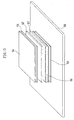
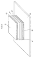
having three sets of stacked electrodes is shown in FIG. 9.
First, a method of producing the bacteria removing
device in accordance with the present invention will be
described. A 30-mesh copper mesh formed of copper wires
having a diameter of 0.22 mm was cut to a size of 10 cm in
width and 10 cm in length, and an end portion thereof was
treated. Furthermore, a lead wire was taken out from the
end portion, and 12 mesh electrodes (a, b and c) were
prepared.
Next, 13 insulating layers (a', b' and c') each
formed of a 30-mesh polyester mesh having a thickness of
about 30 µ um and larger than the above-mentioned copper
mesh by 1 cm in width and length were prepared. In FIG. 9,
the number of these layers is omitted.
First, one of the above-mentioned insulating layer is
prepared, and at the center thereof, each of the above-mentioned
copper meshes and insulating meshes are stacked
alternately so that the copper meshes are insulated from
each other; then, the last insulating layer is stacked.
The lead-out portion of the first copper mesh is connected
to the lead-out portion of the fourth copper mesh, and the
lead-out portion of the seventh copper mesh is connected to
the lead-out portion of the tenth copper mesh. In the same
manner, the lead-out portion of the "n"th copper mesh is
connected to the lead-out portion of the (n + 3)th copper
mesh, whereby three sets of electrodes comprising four
connected copper meshes are formed.
These three sets of electrodes are accommodated in
the box-shaped bacteria removing container, and an inflow
guide plate is provided above the electrode on the side of
the second copper such that no turbulence is occurred at
the inflow port for a liquid to be treated and in the
liquid. On the other hand, a discharge port for the liquid
under treatment and a guide plate are provided below the
inflow port for the liquid under treatment, thereby forming
a bacteria removing device.
The timing of voltage application to the electrodes
of this device and the operation principle thereof are the
same as those of the embodiment 5.
Furthermore, as a material for the electrode,
conventional materials can be used; aluminum foil, copper
foil, a punching metal, a foamed metal, carbon fiber, a
carbon mesh, a porous sintered metal and the like can be
exemplified.
Moreover, as a material for the insulating layer,
insulating materials allowing the microorganism to pass
through, such as glass wool, a polypropylene mesh, a
polyester mesh or non-woven fabrics thereof, porous
ceramics and the like can be used for example.
In addition, as a result of earnest studies, the
inventors of the present invention have found that the
bacteria removing device in accordance with the
embodiment
5 should preferably be operated in the following conditions,
for example.
The operation principle of the bacteria removing
device in accordance with the present embodiment is
described above; by appropriately controlling the above-mentioned
sweeping rate for voltage application to the
above-mentioned electrodes, microorganism can be moved from
the outer peripheral portions of the sheet-shaped
electrodes wound in the form of vortex to the central
portion.
By producing a plurality of the containers provided
with the electrodes described in the above-mentioned
embodiments 5 and 6, and by connecting the lead-out
portions provided for the respective electrodes to those
corresponding thereto, it is possible to obtain a bacteria
removing device in which plural containers provided with
electrodes are connected.
By employing this kind of structure, it is possible
to increase the amount of treatment, and it is possible to
further enhance the microorganism removal effect for a
bacteria liquid to be treated.
Due to the bacteria removing device of the present
invention, it is possible to decrease the concentration of
microorganism in a bacteria liquid to be treated by using
fewer process steps, more easily, in a shorter time, more
continuously and stably in comparison with a method for
decreasing the concentration of microorganism by filtering
the bacteria liquid to be treated containing a
microorganism. Furthermore, the bacteria removing device
of the present invention, by appropriately selecting the
materials of the components, can be converted into a
disposable type or a continuous-use type and has a wide
range of applications. Furthermore, the device can be used
as a bacteria removing device for water-purification pipes
and food industry, and can also be used to remove a
microorganism from circulation water system in living
environment for example, as another effect thereof.
(iii) Electric appliance provided with a heat exchanger
Furthermore, the present invention provides an
electric appliance provided with a heat exchanger,
comprising an electrode member opposed to the heat
exchanger with a space therebetween and disposed in a
condensed dew water discharged from the above heat
exchanger at a position in which the electrode member is in
contact with the above condensed dew water together with
the surface of the above heat exchanger, and a voltage
application means provided between the above heat exchanger
and the above electrode member in order to move a
microorganism present between the above heat exchanger and
the above opposed member to the above electrode member
direction.
In this case, it is effective that the voltage
application means can apply a voltage in a range such that
it does not cause the electrolysis of the condensed dew
water.
In the above electric appliance, it is effective that
the surface of the opposed member has a material capable of
adsorbing and holding the microorganism, and it is also
effective that the surface of the opposed member has a
structure capable of adsorbing and holding the
microorganism.
Furthermore, it is effective that the surface of the
opposed member has a material capable of disinfecting the
microorganism or capable of restricting the proliferation
of microorganism, and it is effective that the surface of
the opposed member has a structure capable of disinfecting
the microorganisms or capable of restricting the
proliferation of the microorganism. Furthermore, it is
effective that the opposed member has an easily removable
and cleanable structure.
Embodiment 7
FIG. 10 is a schematic perspective view showing a
heat exchanger portion in an air conditioner in accordance
with the present invention. An aluminum mesh 32 obtained
by weaving aluminum wires of 50 µm into a mesh at an
opening ratio of 50% and used as a metallic member, a
hydrophilic non-woven fabric 33 of fibers comprising a
hydrophilic and water-impermeable paper or the like, which
is surface-treated with an antifungal agent or an
antimicrobial agent such as thiabenzoimidazole (TBZ), a
quaternary ammonium salt or a silver-based antimicrobial
agent, and a polypropylene non-woven fabric 34 having a
thickness of about 100 µm for securing the hydrophilic non-woven
fabric 33 to the aluminum mesh 32 were stacked. This
obtained laminate is disposed below the radiating aluminum
fin 35 of the heat exchanger to which the condensed dew
water of the heat exchanger flows down. A positive voltage
of 0.7 V is applied to the aluminum mesh 32 with respect to
the radiating fin 35 of the heat exchanger by a voltage
application means 36.
In the air conditioner having the above-mentioned
structure, at least one end thereof is in contact with a
condensed dew water receiving pan (drain pan), and the
condensed dew water in the drain pan is electrically
connected to the level of the heating exchanger. The
condensed dew water discharged from the drain pan is
drained to prevent backflow, thereby electrically insulated
from a catch basin used as a final discharge destination.
With this structure, the microorganism on the surface
of the heat exchanger moves to the surface of the aluminum
mesh 32 and is adsorbed by the hydrophilic non-woven fabric
33 on the surface of the aluminum mesh 32. At the same
time, the proliferation of the microorganism is prevented
by the antimicrobial and antifungal ingredients contained
in the non-woven fabric 33.
In the above-mentioned air conditioner, the condensed
dew water from which the microorganism is removed gathers
in the drain pan, and is discharged to the catch basin.
The movement of the microorganism from the surface of the
heat exchanger (aluminum) to the surface of the metallic
member (aluminum) is occurred; however, since the catch
basin is insulated physically and electrically from the
drain pan by water draining, the movement of the
microorganism from the catch basin does not occur.
Furthermore, the air conditioning device having this
structure is easily removable from the main unit of the air
conditioner, and the hydrophilic non-woven fabric 33
therein is replaceable. When the effectiveness of the
antimicrobial and antifungal agent applied to treat the
hydrophilic non-woven fabric 33 is lowered and when the
number of the microorganism adsorbed and held inside the
non-woven fabric is increased, the effect can be restored
by replacing the non-woven fabric 33 with a new one.
In the embodiment described above, the explanation
with respect to an air conditioner is given; however, the
embodiment can also be applied to electric appliances
provided with heat exchangers such as car-mounted air
conditioners, refrigerators, ice-making appliances, water-cooling
appliances, cold reservoirs and vending machines.
In accordance with the electric appliance provided
with the heat exchanger in accordance with the present
invention, the cleanness of the surface of the heat
exchanger containing a microorganism, which cannot be
removed conventionally, can be enhanced and attained by
electrochemical reactions. For this reason, the
proliferation of microorganisms during the stop period of
the electric appliance can be restricted, and the heat
exchanger can be used as a part of infection prevention
measures at hospitals and the like. The industrial value
of the present invention is therefore great.
(2) With respect to second electrochemical device
(i) Microorganism concentration condensing device and
microorganism concentration increasing method
Next, the present invention provides a microorganism
concentration condensing device comprising a microorganism
concentration condensing cell comprising two or more kinds
of electrodes (metallic members) disposed opposite to each
other with a space therebetween and having different
oxidation/reduction potentials and a circuit (a short-circuit
portion) for short-circuiting the above-mentioned
electrodes, wherein a test liquid containing a
microorganism is held in the above-mentioned space, and the
microorganism is moved from an electrode having a higher
oxidation/reduction potential to an electrode having a
lower oxidation/reduction potential by short-circuiting the
above-mentioned electrodes thereby to condense the
concentration of the microorganism in the above-mentioned
test liquid.
In the above-mentioned microorganism concentration
condensing device, it is effective that the above cell has
an introduction portion for the above test liquid at one
end in the vicinity of the electrode having a higher
oxidation/reduction potential, a discharge portion for the
above test liquid at the other end, and a microorganism
discharge portion and/or a microorganism adsorption portion
in the vicinity of the electrode having a lower
oxidation/reduction potential.
Furthermore, it is effective that an electrically
insulating structural member through which the above test
liquid can move is disposed in the above-mentioned space.
Furthermore, it is effective that the electrodes
other than the electrode having the lowest
oxidation/reduction potential have a structure capable of
allowing the above test liquid to flow into the above space.
Furthermore, it is effective that the above-mentioned
structure is a porous, mesh or brush structure.
Furthermore, it is effective that the electrodes
other than the electrode having the lowest
oxidation/reduction potential have the shape of a film
through which a microorganism can pass, and that the
electrode is stacked on the surface of an electrically
insulating structural member through which the above test
liquid can move.
Furthermore, a microorganism concentration condensing
device having a plurality of the microorganism
concentration condensing cells is also effective.
Furthermore, the present invention also provides a
microorganism concentration condensing method comprising
the steps of: disposing two or more kinds of electrodes
having different oxidation/reduction potentials, opposite
to each other with a space therebetween, (b) introducing a
test liquid containing a microorganism in the above-mentioned
space, (c) short-circuiting the above-mentioned
electrodes, and (d) moving the microorganism from an
electrode having a higher oxidation/reduction potential to
an electrode having a lower oxidation/reduction potential
by using the above-mentioned steps (b) and (c) to recover a
condensed test liquid.
The inventors of the present invention have found
that a microorganism can be allowed to migrate from a
negative electrode to a positive electrode and the
concentration of the microorganisms in the test liquid can
be increased by forcibly applying a voltage across the
electrodes in contact with the test liquid containing a
microorganism. In other words, microorganisms such as
colon bacilli and yellow staphylococci have charges on the
surfaces and move depending on an electric field.
However, through experiments conducted earnestly by
using electrodes made of various metals, the microorganism
was able to be moved by using two kinds of electrodes and
by simply short-circuiting the two electrodes, without
forcibly applying a voltage across the electrodes.
Then, the inventors of the present invention have
thus found that the different kinds of metallic members
have different oxidation/reduction potentials (ionization
tendencies), and have discovered that the microorganism
moves from one metallic member to the other metallic member
because of the above-mentioned difference in the
oxidation/reduction potential. More specifically, the
microorganism moves from a metallic member having a higher
oxidation/reduction potential (having a lower ionization
tendency) to a metallic member having a lower
oxidation/reduction potential (having a higher ionization
tendency).
In other words, the second electrochemical device in
accordance with the present invention has been completed on
the basis of the new findings regarding the
oxidation/reduction potentials, obtained as the result of
the above-mentioned examination.
The present invention relates to a microorganism
concentration condensing device having a microorganism
concentration condensing cell comprising two or more kinds
of electrodes disposed opposite to each other with a space
therebetween and having different oxidation/reduction
potentials and a short-circuit portion for short-circuiting
the above-mentioned electrodes, wherein the above-mentioned
test liquid is held in the above space and a microorganism
is moved from an electrode having a higher
oxidation/reduction potential to an electrode having a
lower oxidation/reduction potential by short-circuiting the
above electrodes, thereby to condense the concentration of
the microorganism in the above test liquid.
For convenience in understanding, the present
invention will be explained below, while the above cell
having two kinds of electrodes is taken as a typical
example.
As the combination of the two kinds of electrodes,
the combination may only contain electrodes having
different oxidation/reduction potentials; however, in view
of surely moving the microorganism in particular, it is
preferable that the difference between the
oxidation/reduction potentials is about 1.0 V.
Herein, in TABLE 2, some metallic members that can be
used for the electrodes of the present invention and their
oxidation/reduction potentials (standard electrode
potentials E° in aqueous solution (25°C)) were exemplified.
| Kind of metal | Oxidation/reduction potential (V) |
| Au | +1.69 |
| Pt | +1.19 |
| Ag | +0.799 |
| Cu | +0.337 |
| Pb | -0.126 |
| Ni | -0.25 |
| Sb | -0.26 |
| Co | -0.277 |
| W | -0.32 |
| Fe | -0.440 |
| Sn | -0.50 |
| Cr | -0.744 |
| Zn | -0.763 |
| V | -1.23 |
| Al | -1.66 |
| Ti | -1.72 |
| Zr | -1.95 |
| Mg | -2.27 |
Among the metals listed in TABLE 2, it is preferable
to use the combination of Au (+1.69 V) and Fe (-0.440 V) in
considering that the difference between the
oxidation/reduction potentials is large. Furthermore, in
considering that they are inexpensive and easy to obtain,
it is preferable to use the combination of Cu (+0.337 V)
and Zn (-0.763 V).
The structure and form of this kind of metallic
member are not limited in particular; a film form, a plate
form, a bar form and the like through which the
microorganism can pass are taken as examples. In addition,
the metallic member may be a sintered metallic member, or a
metallic member made by evaporation or sputtering.
However, in the present invention, since the
microorganism is moved (allowed to migrate) from a metallic
member having a higher oxidation/reduction potential to a
metallic member having a lower oxidation/reduction
potential, it is therefore preferable that an introduction
portion and a discharge portion for a test liquid
containing a microorganism are provided in the vicinity of
the metallic member having the higher oxidation/reduction
potential and that a microorganism discharge portion or a
microorganism adsorption portion (described later) is
provided in the vicinity of the metallic member having the
lower oxidation/reduction potential.
In view of these, it is preferable that the metallic
members other than the metallic member having the lowest
oxidation/reduction potential have a structure wherein the
above test liquid can flow into the above space. More
specifically, the metallic member can have a porous
structure such as a foamed metal, or a mesh or brush
structure, for example.
Furthermore, the metallic members other than the
metallic member having the lowest oxidation/reduction
potential have the form of a film through which the
microorganism can pass, and the metallic member may be
stacked on the surface of an electrically insulating
structural member through which the above test liquid can
move.
The metallic members having low oxidation/reduction
potentials may have this kind of structure and form as a
matter of course.
Furthermore, it is preferable that an electrically
insulating structural member through which the above-mentioned
test liquid can move is disposed in the above
space. This facilitates the capture of the microorganism
contained in the test liquid in the above space, whereby
the concentration of the microorganism can be condensed
efficiently, and the scattering of the test liquid
containing a microorganism to the outside can be prevented
as much as possible.
As this kind of electrically insulating structural
member, a non-woven fabric, a fabric, a continuous foam,
paper and the like can be exemplified. In addition, as a
material for constituting this structural member,
thermoplastic resins such as polyester including
polyethylene terephthalate and polypropylene can be
exemplified.
Since this kind of electrically insulating structural
member has captured the microorganism after use, it is made
replaceable with a new one.
The above cell constituting the microorganism
concentration condensing device of the present invention
has a short-circuit portion for electrically short-circuiting
two kinds of metallic members. By short-circuiting
the above two kinds of metallic members, an
electric field is generated between the metallic members
having different oxidation/reduction potentials, whereby
the microorganism can be moved.
This kind of short-circuit portion may be short-circuited
in advance before the above test liquid is
introduced, or can be short-circuited after the above test
liquid is introduced.
It is preferable that the above short-circuit portion
is constituted not to have a contact with the above test
liquid so that the movement of the microorganism does not
occur by the potential difference between the short-circuit
portion and the above metallic members. For example, from
the above metallic members, lead wires formed of the
corresponding metals may be taken out and connected.
Furthermore, in the above cell, since the
concentration of the microorganism in the test liquid
containing a microorganism present in the vicinity of the
metallic member having a higher oxidation/reduction
potential is lowered, it is preferable to provide the above
test liquid introduction portion for introducing (flowing)
the above test liquid to one end in the vicinity of the
metallic member, and that a discharge portion for
discharging the test liquid having a lowered concentration
of the microorganism is provided at the other end in the
vicinity of the metallic member.
On the other hand, it is preferable to provide a
discharge portion for discharging the above test liquid in
which the microorganism is moved by the electric field and
concentrated in the vicinity of the metallic member having
a lower oxidation/reduction potential.
Furthermore, it is preferable to provide a
microorganism adsorption portion in the vicinity of the
metallic member having a lower oxidation/reduction
potential. This adsorption portion can be formed by making
the metallic member having a lower oxidation/reduction
potential adsorbed onto silica gel or the like in layers.
As described above, although the case having two
kinds of metallic members are used has been explained, even
in the case having three or more kinds of metallic members
are used, a microorganism condensation cell can also be
produced by using a similar method.
For example, it is possible to have a structure in
which a metallic member having the highest
oxidation/reduction potential, an electrically insulating
structural member, a metallic member having the second
highest oxidation/reduction potential, an electrically
insulating structural member, ....., and a metallic member
having the lowest oxidation/reduction potential are stacked
in this order.
Furthermore, it is also possible to appropriately
modify the arrangement of the metallic members to have a
design such that the test liquid containing a microorganism
is introduced from the vicinities of the plural metallic
members and the test liquid after condensation is taken out
from the vicinities of the other plural metallic members.
As describe above, the microorganism concentration
condensing device of the present invention basically
comprises the above microorganism concentration condensing
cell.
For this reason, the microorganism concentration
condensing device of the present invention may have a
plurality of the above-mentioned microorganism
concentration condensing cells. In this case, the plural
cells may be connected mechanically to each other so that
the short-circuit portion of each cell may be set on and
off by a single switch. In addition, a single introduction
portion may be formed by connecting the test liquid
introduction portions of the respective cells. This is
similarly applicable to the discharge portion for
discharging the test liquid having a decreased
concentration of the microorganism and to the test liquid
discharge portion for discharging the test liquid having a
condensed concentration of the microorganism.
The present invention also relates to a microorganism
concentration condensing method based on the principle of
the above microorganism concentration condensing device.
More specifically, the present invention relates to a
microorganism concentration condensing method comprising
the steps of: (a) disposing two or more kinds of metallic
members having different oxidation/reduction potentials,
opposite to each other with a space therebetween, (b)
introducing a test liquid containing a microorganism in the
above space, (c) short-circuiting the above metallic
members, and (d) moving the microorganism from a metallic
member having a higher oxidation/reduction potential to a
metallic member having a lower oxidation/reduction
potential by using the above steps (b) and (c) to recover
the above test liquid after condensed.
These steps may be carried out in accordance with the
explanation of the above-mentioned microorganism
concentration condensing device of the present invention
and, however, the sequence of step (a), step (b) and step
(c) is not restricted in particular. For example, the two
kinds of metallic members having a space therebetween and
short-circuited beforehand may be immersed in the test
liquid containing a microorganism, or the two kinds of
metallic members having a space therebetween may be short-circuited
after immersed in the test liquid containing a
microorganism.
The present invention will be described below more
specifically by using embodiments but is not limited
thereto.
Embodiment 8
The present embodiment will be described referring to
the drawings.
A gold mesh 41 woven by using a gold wire having a
diameter of 50 µm and an opening ratio of 50%, a non-woven
fabric spacer (electrically insulating structural member)
42 formed of polyethylene terephthalate and having a
thickness of about 100 µm. and an iron foil sheet 43 having
a thickness of 100 µm were stacked as shown in FIG. 11
thereby to form a microorganism concentration condensing
cell (10 cm by 10 cm) 46.
Next, as shown in FIG. 12, after the cells, five in
number, were disposed together so as to be arranged in
star-like directions, one end of the gold mesh 41 was
short-circuited to one end of the iron foil sheet 43 in
each cell to form a short-circuit portion, thereby a
microorganism concentration condensing device 47 in
accordance with the present invention was obtained. The
gold mesh 41 and the iron foil sheet 43 were provided with
a terminal portion 44 or 45 for forming the short-circuit
portion, respectively.
Next, the obtained microorganism concentration
condensing device was gently immersed in a microorganism
suspension (1 litter) containing about 1000 cfu/ml of colon
bacilli as the microorganism. By this immersion, the above
suspension flowed into the space in the non-woven spacer 42,
and the microorganism moved toward the iron foil sheet 43
at a rate of about 2 µm/sec.
Embodiment 9
A microorganism concentration condensing cell and a
microorganism concentration condensing device were produced
in the same manner as that for the embodiment 8, except
that a zinc foil sheet having a thickness of 100 µm and
provided with silica gel on the surface was used as the
microorganism adsorption layer, instead of the iron foil
sheet 43.
When evaluated just as in the case of the embodiment
8, effects similar to those of the embodiment 1 were
obtained.
Embodiment 10
A gold mesh woven by using a gold wire having a
diameter of 50 µm and an opening ratio of 50%, a non-woven
fabric spacer formed of polyethylene terephthalate and
having a thickness of about 100 µm, an iron mesh woven by
using an iron wire having a diameter of 100 µm and an
opening ratio of 50%, and a zinc foil sheet having a
thickness of 100 µm and provided with silica gel on the
surface as the microorganism adsorption layer were stacked
to form a microorganism concentration condensing cell.
Next, by short-circuiting one end of the gold mesh to one
end of the iron mesh, and one end of the iron mesh to one
end of the zinc foil sheet, a microorganism concentration
condensing device in accordance with the present invention
was obtained.
Then, when evaluated just as in the case of the
embodiment 8, effects similar to those of the embodiment 8
were obtained.
In accordance with the microorganism concentration
condensing device of the present invention, the
condensation of the microorganism in the above test liquid
can be carried out by using fewer process steps, more
easily, in a shorter time, at higher quantitative and more
stably in comparison with a method in which the
condensation of the concentration of the microorganisms is
carried out by filtering and re-extracting the test liquid
containing a microorganism.
Furthermore, when the device is used as a bacteria
removing device, an effect of being capable of easily
removing microorganisms is obtained without using an device
such as an external power source.
(ii) Blood component induction device and blood component
induction method
Furthermore, the present invention provides a blood
component induction device having a blood component
induction cell comprising two or more kinds of electrodes
disposed opposite to each other with a space therebetween
and having different oxidation/reduction potentials and a
circuit for short-circuiting the above electrodes, wherein
a blood sample is held in the above space, and a blood cell
component and/or a microorganism contained in the blood
sample are moved from an electrode having a higher
oxidation/reduction potential to an electrode having a
lower oxidation/reduction potential by short-circuiting the
above electrodes, thereby to separate and remove the blood
cell component and/or the microorganism from the above
blood sample.
In this case, the test liquid containing particles
covered with a protein corresponds to the blood sample
containing a blood cell component and/or a microorganism.
In the above blood component induction device, it is
effective that the above cell has an introduction portion
for the above blood sample at one end in the vicinity of
the electrode having a higher oxidation/reduction potential,
a discharge portion or a holding portion for the above
blood sample at the other end, and a discharge portion for
discharging the microorganism contained in the blood sample
and an adsorption portion for adsorbing the microorganism
contained in the blood sample in the vicinity of the
electrode having a lower oxidation/reduction potential,
and/or has an adsorption portion for adsorbing the blood
cell component contained in the blood sample.
Furthermore, it is effective that an electrically
insulating structural member through which the blood
component in the above blood sample can move is provided in
the above space.
Furthermore, it is effective that the above electrode
has the form of a mesh, a net, a film, a line or a brush.
Furthermore, it is effective that the electrodes
other than the electrode having the lowest
oxidation/reduction potential have a shape in which the
above blood sample can flow into the above space. It is
effective that the shape is a porous, mesh or brush.
Furthermore, it is effective that the electrodes
other than the electrode having the lowest
oxidation/reduction potential have the shape of a film
through which the blood cell component and/or the
microorganism contained in the blood sample can pass, and
that the electrode is stacked on the surface of an
electrically insulating structural member through which the
above blood sample can move.
Furthermore, it is effective that a plurality of the
above blood component induction cells are provided.
Furthermore, the present invention also provides a
blood component induction method comprising the steps of:
(a) disposing two or more kinds of electrodes having
different oxidation/reduction potentials, opposite to each
other with a space therebetween, (b) introducing a blood
sample in the above-mentioned space, (c) short-circuiting
the above-mentioned electrodes to move a blood cell
component or a microorganism contained in the blood sample
from an electrode having a higher oxidation/reduction
potential to an electrode having a lower
oxidation/reduction potential, and (d) recovering the blood
sample from which the blood component are separated or the
blood sample from which the microorganism are removed by
using the step (c).
As described above, through experiments conducted
earnestly by the inventors of the present invention by
using electrodes made of various metals, the microorganism
contained in the blood sample was able to be moved by using
two electrodes made of different materials and by simply
short-circuiting the two electrodes, without forcibly
applying a voltage across the electrodes. In addition, not
only the microorganism but also the blood cell component in
the blood sample can be moved.
And the inventors of the present invention have
discovered that the microorganism contained in the blood
sample move from one metallic member to the other metallic
member because the above different kinds of metallic
members have different oxidation/reduction potentials
(ionization tendencies). Furthermore, the inventors have
also discovered that the blood cell component contained in
the blood sample move from one metallic member to the other
metallic member because of the difference between the above
oxidation/reduction potentials.
More specifically, the microorganism and the blood
cell component contained in the blood sample move from the
metallic member having a higher oxidation/reduction
potential (having a lower ionization tendency) to the
metallic member having a lower oxidation/reduction
potential (having a higher ionization tendency).
In other words, the blood component induction device
in accordance with the present invention has been completed
on the basis of the new findings regarding the
oxidation/reduction potentials, obtained as the result of
the above examination.
The present invention relates to a blood component
induction device having a blood component induction cell
comprising two or more kinds of metallic members disposed
opposite to each other with a space therebetween and having
different oxidation/reduction potentials and a short-circuit
portion for short-circuiting the above-mentioned
metallic members, wherein a blood sample is held in the
above-mentioned space, and a blood cell component and/or a
microorganism contained in the blood sample are moved from
a metallic member having a higher oxidation/reduction
potential to a metallic member having a lower
oxidation/reduction potential by short-circuiting the
above-mentioned metallic members, thereby to separate and
remove the blood cell component and/or the microorganism
from the above-mentioned blood sample.
"Blood sample" in the present invention is not only
the blood itself but also a concept including blood diluted
with isotonic sodium chloride solution, and liquid obtained
by mixing component blood, pure water, an osmotic
adjustment liquid, further water in living environment,
waste water containing unwanted bacteria, a liquid
containing a body fluid component, and the like, for
example. Furthermore, it is also a concept widely
including fluids in view of the fact that the blood sample
may have some viscosity.
Furthermore, in accordance with the blood component
induction device of the present invention, not only the
blood cell component in a blood sample but also the
microorganism, if contained, can be separated and removed.
Consequently, the device can not only separate and remove
the blood cell component or the microorganism but also
separate and remove both simultaneously.
For convenience in understanding, the blood component
induction device in accordance with the present invention
will be explained below, while the above-mentioned cell
including two kinds of metallic members is taken as a
typical example.
The above-mentioned metallic members in accordance
with the present invention function as the so-called
electrodes. As the combination of the two kinds of
metallic members, the combination of metallic members
having different oxidation/reduction potentials may be used
and, in view of securely moving the blood component and the
microorganism contained in the blood sample in particular,
it is preferable that the difference between the
oxidation/reduction potentials is about 1.0 V.
Herein, some metallic members that can be used and
their oxidation/reduction potentials (standard electrode
potentials E° in aqueous solution (25°C)) are shown in
TABLE 2.
The structure and form of this kind of metallic
member are not limited in particular and a mesh form, a
film form, a line form, a brush form, a plate form, a bar
form, a porous form and the like, through which the blood
component or the microorganism contained in the blood
sample can pass, are exemplified. In addition, the
metallic member may be a sintered metallic member, or a
metallic member made by plating, evaporation, CVD or
sputtering.
Furthermore, in the case when a fiber-form metal is
used, a mesh-form electrode or non-woven fabric-form
electrode may be obtained by mixing natural fibers or
synthetic fibers with metallic fibers.
However, in the present invention, since the blood
cell component or the microorganism contained in the blood
sample are moved (allowed to migrate) from a metallic
member having a higher oxidation/reduction potential to a
metallic member having a lower oxidation/reduction
potential, it is therefore preferable that an introduction
portion and a discharge portion for a blood sample are
provided in the vicinity of the metallic member having the
higher oxidation/reduction potential, and that a discharge
portion or a adsorption portion for the blood component or
the microorganism contained in the blood sample is provided
in the vicinity of the metallic member having the lower
oxidation/reduction potential.
In view of these, it is preferable that the metallic
members other than the metallic member having the lowest
oxidation/reduction potential have a form such that the
above blood sample can flow into the above space. The
metallic member can have a porous form, a mesh form or a
brush form, for example. The metallic member may be a
fabric, mesh or brush formed of thin metal wires or metal-treated
fibers on the surface, for example. As described
above, the metallic member may be formed by mixing and
weaving natural fibers and synthetic fibers.
The metallic members having low oxidation/reduction
potentials may have this kind of structure and form as a
matter of course.
Furthermore, it is preferable that an electrically
insulating structural member through which the blood
component and the like in the above blood sample can move
is disposed in the above space. This facilitates the
capture of the test sample in the above space, thereby the
removal of the blood cell component or the microorganism
contained in the blood sample and the separation of the
blood component can be performed efficiently, and the
scattering of the blood sample to the outside can be
prevented as much as possible.
As this kind of electrically insulating structural
member, a non-woven fabric, a fabric, a continuous foam,
paper and the like can be exemplified. In addition, as a
material for constituting this structural member, cotton or
thermoplastic resin such as polyester including
polyethylene terephthalate or polypropylene can be
exemplified.
Since this kind of electrically insulating structural
member has captured the blood cell component or the
microorganism contained in the blood sample after use, it
is made replaceable with a new one.
In particular, in the case when the metallic members
other than the metallic member having the lowest
oxidation/reduction potential are formed into a film,
through which the blood cell component or the microorganism
contained in the blood sample can pass, it is preferable
that the metallic member is stacked on the surface of the
electrically insulating structural member through which the
above blood sample can move.
The above-mentioned cell constituting the blood
component induction device of the present invention has a
short-circuit portion for electrically short-circuiting two
kinds of metallic members. By short-circuiting the above
two kinds of metallic members, an electric field is
generated between the metallic members having different
oxidation/reduction potentials, thereby the blood cell
component and/or the microorganism contained in the blood
sample can be moved.
Such a short-circuit portion may be short-circuited
in advance before the blood sample is introduced, or may be
short-circuited after the blood sample is introduced.
It is preferable that the above short-circuit portion
is structured not to contact with the blood sample so that
the blood cell component and/or the microorganism contained
in the blood sample are not moved by the potential
difference between the short-circuit portion and the above
metallic members. For example, from the above-mentioned
metallic members, lead wires formed of the corresponding
metals may be taken out and connected.
Furthermore, in the above cell, since the
concentration of the blood cell component and/or the
microorganism contained in the blood sample present near
the metallic member having a higher oxidation/reduction
potential is lowered, it is preferable to provide an
introduction portion for introducing (flowing) the blood
sample to one end in the vicinity of the metallic member
and to provide a discharge portion for discharging the
blood sample having a decreased concentration of the blood
cell component and/or the microorganism at the other end
in the vicinity of the metallic member.
On the other hand, it is preferable that a discharge
portion for discharging the blood sample in which the blood
cell component and/or the microorganism contained in the
blood sample are moved by the electric field and condensed
is provided in the vicinity of the metallic member having a
lower oxidation/reduction potential.
Furthermore, it is preferable that an adsorption
portion for the blood cell component and/or the
microorganism contained in the blood sample is provided in
the vicinity of the metallic member having a lower
oxidation/reduction potential. This adsorption portion can
be formed by making the metallic member having a lower
oxidation/reduction potential adsorb silica gel, polymer
absorber or the like in layers. Moreover, a water
absorbing layer for absorbing the blood sample may also be
provided.
As described above, although the case having two
kinds of metallic members are used has been explained, even
in the case having three or more kinds of metallic members
are used, an induction cell for the blood component
contained in the blood sample can also be produced by using
a similar method.
For example, it is possible to have a structure in
which a metallic member having the highest
oxidation/reduction potential, an electrically insulating
structural member, a metallic member having the second
highest oxidation/reduction potential, an electrically
insulating structural member, ..., an electrically
insulating structural member, and a metallic member having
the lowest oxidation/reduction potential are stacked in
this order.
Furthermore, it is also possible to appropriately
modify the arrangement of the metallic members to have a
design in which the blood sample is introduced from the
vicinities of the plural metallic members and the blood
sample after the removal of bacteria or the separation of
blood cell component is taken out from the vicinities of
the other plural metallic members.
As describe above, the blood component induction
device of the present invention is basically formed of the
above blood component induction cell.
Therefore, the blood component induction device of
the present invention may have a plurality of the above
blood component induction cells. In this case, the plural
cells may be connected mechanically to each other so that
the short-circuit portion of each cell can be set on and
off by a single switch. In addition, a single introduction
portion may be formed by connecting the blood introduction
portions of the respective cells. This is similarly
applicable to the discharge portion for discharging the
blood sample having a decreased concentration of the blood
cell component or the microorganism and to the discharge
portion for discharging the blood sample having an
increased concentration of the blood cell component or the
microorganism.
The present invention also relates to a blood
component induction method based on the principle of the
above-mentioned blood component induction device.
More specifically, the present invention relates to a
blood component induction method comprising the steps of:
(a) disposing two or more kinds of metallic members having
different oxidation/reduction potentials, opposite to each
other with a space therebetween, (b) introducing a blood
sample in the above-mentioned space, (c) short-circuiting
the above-mentioned metallic members, and (d) recovering
the blood sample from which bacteria are removed by moving
a blood cell component and/or a microorganism contained in
the blood sample from a metallic member having a higher
oxidation/reduction potential to a metallic member having a
lower oxidation/reduction potential by using the above-mentioned
steps (b) and (c).
These steps may be carried out in accordance with the
explanation of the above-mentioned blood component
induction device of the present invention but the sequence
of step (a), step (b) and step (c) is not restricted in
particular. For example, the two kinds of metallic members
having a space therebetween and short-circuited beforehand
may be immersed in the blood sample, or the two kinds of
metallic members having a space therebetween may be short-circuited
after immersed in the blood sample.
The blood component induction device in accordance
with the present invention having the above-mentioned
structure can be applied to for example first-aid adhesive
tapes, sanitary napkins, medical adhesive tapes, sterilized
gauze and sterilized sheets, and more specifically articles
such as wound protection dressing, catheter fixing pads,
hemostatic adhesive tapes, sterilized skin closures,
sterilized ramie sheets, disposable surgical operation
gowns and the like.
In the case when the device is applied to a first-aid
adhesive tape in particular, it is effective to provide a
disinfecting layer obtained by applying a disinfecting
agent to the surface of a metallic member having a low
oxidation/reduction potential in order to induce the
microorganism to the vicinity of the metallic member having
a low oxidation/reduction potential. Furthermore, in the
case when the device is applied to a sanitary napkin, it is
effective to provide a water-absorbing layer formed of
water-absorbing resin in order to absorb moisture.
Furthermore, the shape and dimensions of the blood
component induction device in accordance with the present
invention are not limited in particular, but may be
adjusted appropriately depending on the shape and
dimensions of articles to be applied.
The blood component induction device in accordance
with the present invention will be described below more
specifically by using embodiments but is not limited
thereto.
Embodiment 11
An example in which the blood component induction
device in accordance with the present invention is applied
to a first-aid adhesive tape will be described referring to
a drawing.
FIG. 13 is a view showing the structure of a first-aid
adhesive tape in accordance with an embodiment of the
blood component induction device of the present invention.
As shown in FIG. 13, in the first-aid adhesive tape in
accordance with the present invention, a mesh-shaped
electrode 51 (a metallic member having a higher
oxidation/reduction potential) formed of a mixture of gold
wires and synthetic fibers being hard to stick to tissue,
each having a diameter of 10 µm. and spacers 52 (two
sheets) obtained by processing fibers, which are
hydrophilic and hard to stick to tissue, into the shape of
a mesh were stacked. The spacers 52 were made high in
electric insulation. Furthermore, under the spacers 52, an
induction electrode 53 (a metallic member having a lower
oxidation/reduction potential) obtained by processing thin
titanium wires into the shape of a mesh was disposed, and a
protection layer 54 comprising the same material and having
the same structure as those of the spacer 52 was disposed
at the uppermost face. A disinfectant was applied to the
spacer 52 on the side of the induction electrode 53 to form
a disinfection layer. A blood component induction cell
having this kind of structure was formed. On the outside
of the induction electrode 53 of this cell, a polyvinyl
chloride tape 56 with an adhesive applied to one side
thereof was provided, and the mesh-shaped electrode 51 was
short-circuited with the induction electrode 53 at a
portion not contacting with blood, thereby forming a first-aid
adhesive tape.
The principle of separating and removing the blood
components and/or microorganisms from a blood sample in
this kind of first-aid adhesive tape will be described
below.
More specifically, blood near a wound is polluted
with unwanted bacteria from around the wound or the
surrounding skin. The polluted blood at the wound passes
through the protection layer 54 and penetrates the mesh-shaped
electrode 51. As described above, when different
kinds of short-circuited metals are opposed with a space
therebetween, the blood cell component and/or the unwanted
bacteria in the blood move from the metal having a higher
oxidation/reduction potential to the metal having a lower
oxidation/reduction potential. By using the mesh-shaped
electrode 51 as the electrode having a higher
oxidation/reduction potential, by using the induction
electrode 53 as the electrode having a lower
oxidation/reduction potential, and by using the spacers 52
as the space provided between the metals at this time, the
unwanted bacteria contained in the blood are induced to the
vicinity of the induction electrode 53. As a result, the
wound and the surrounding area thereof are disinfected.
The size of the cell used herein differs depending on
the portion and size of a wound to be treated and it is
preferable that the size should be at least 10 mm × 20 mm.
The disinfection layer 55 applied to the spacer 52 adjacent
to the induction electrode 53 further increases reliability
in the effect of bacteria removal.
As a combination of different kinds of metals, a
combination of gold and titanium was described and the
difference between the oxidation/reduction potentials was
about 0.7 V, causing no problem in practice. As
combinations other than that described above, a combination
of gold and stainless steel and a combination of copper and
zinc can also be used.
As a blood sample containing a microorganism, blood
(0.5 ml) containing about 1000 cfu/ml of colon bacilli was
dropped to the protection layer 54 of the above cell.
After this, the flow of the blood and the movement of the
colon bacilli were observed. As a result, it was found
that the above blood flows into the space formed by the
spacers 52 and that the colon bacilli contained in the
blood moved toward the induction electrode 53 at a rate of
about 2 µm/sec.
Embodiment 12
An example in which the blood component induction
device in accordance with the present invention is applied
to a sanitary napkin will be described referring to a
drawing.
FIG. 14 is a view showing the structure of a sanitary
napkin in accordance with another embodiment of the blood
component induction device of the present invention. As
shown in FIG. 14, in the sanitary napkin in accordance with
the present invention, a mesh-shaped electrode 60 formed of
a mixture of gold wires and synthetic fibers being hard to
stick to tissue, each having a diameter of 10 µm, and
spacers 61 (two sheets) obtained by processing fibers,
which are hydrophilic and hard to stick to tissue, into the
shape of a mesh were stacked. The spacers 61 were made
high in electric insulation. Furthermore, under the
spacers 61, an induction electrode 62 obtained by
processing thin titanium wires into the shape of a mesh was
disposed, and a protection layer 63 having a mesh structure
and formed of a water-repellent material was provided at
the uppermost face. Moreover, a water-absorbing layer 64
formed of a water-absorbing resin was provided on the
spacer 61 on the side of the induction electrode 62.
A blood component induction cell having this kind of
structure was formed. On the outside of the induction
electrode 62 of this cell, a water-impermeable sheet 65 was
provided, thereby forming a sanitary napkin.
The principle of separating and removing the blood
components and/or microorganisms from a blood sample in
this kind of sanitary napkin will be described below.
More specifically, polluted blood passes through the
protection layer 63 and penetrates the mesh-shaped
electrode 60. As described above, when different kinds of
short-circuited metals are opposed with a space
therebetween, the blood cell component and/or the unwanted
bacteria in the blood move from the metal having a higher
oxidation/reduction potential to the metal having a lower
oxidation/reduction potential. By using the mesh-shaped
electrode 60 as an electrode having a higher
oxidation/reduction potential, by using the induction
electrode 62 as an electrode having a lower
oxidation/reduction potential, and by using the spacers 61
as the space provided between the metals at this time, the
unwanted bacteria and/or the blood cell component contained
in the blood are induced to the vicinity of the induction
electrode 63. As a result, the blood cell components
including red blood cells being red in color are separated,
and the unwanted bacteria in the blood are removed.
The size of the cell used herein differs depending on
the portion and size of a wound to be treated and the size
is at least 20 mm × 50 mm.
As a combination of different kinds of metals, a
combination of gold and titanium was described and the
difference between the oxidation/reduction potentials was
about 0.7 V, causing no problem in practice. As
combinations other than that described above, a combination
of gold and stainless steel and a combination of copper and
zinc can also be used.
As the material of the electrodes, a metal mesh was
taken as an example and described but a similar effect can
be obtained even if the material is a metal wire, a porous
metal, a metal-foil-processed member or a surface-treated
member, the surface of which is formed into a metal layer
or film by evaporation or other means. Furthermore, a
similar effect can also be obtained even if the above-mentioned
metallic member has a porous, mesh or brush form.
The blood component induction device of the present
invention can remove the microorganism contained in the
blood sample or separate the blood cell component contained
therein by using fewer process steps, more easily, in a
shorter time and more stably in comparison with a
conventional method in which the microorganism contained in
the blood sample are disinfected.
Furthermore, when the device is used as a bacteria
removing device, an effect of being capable of easily
removing the microorganisms included in the blood sample is
obtained without using an device such as an external power
source.
(iii) Electric appliance provided with a heat exchanger
Furthermore, the present invention provides an
electric appliance provided with a heat exchanger,
comprising a metallic member opposed to the heat exchanger
with a space therebetween and disposed in condensed dew
water flowing from the above-mentioned heat exchanger at a
position in contact with the above-mentioned condensed dew
water together with the surface of the above-mentioned heat
exchanger, and a short-circuit portion for electrically
short-circuiting the above-mentioned heat exchanger and the
above-mentioned metallic member, wherein the
oxidation/reduction potential at the surface of the above-mentioned
metallic member differs from that at the surface
of the above-mentioned heat exchanger in order to move a
microorganism present between the above-mentioned heat
exchanger and the above-mentioned opposed member to the
above-mentioned metallic member.
In this electric appliance, it is effective that the
heat exchanger is formed of aluminum and that the metallic
members are formed of metallic titanium.
Furthermore, it is effective that titanium is
provided in the condensed dew water passage from the heat
exchanger to the drain discharge port, and that drain water
is drained between the water passage and the discharge pipe,
and electrically insulated from the finally discharged
water.
Embodiment 13
The present embodiment will be described referring to
FIG. 15.
FIG. 15 is a schematic perspective view showing a
heat exchanger portion in the air conditioner in accordance
with the present invention. A titanium mesh 71 obtained by
weaving titanium wires of 50 µm into a mesh at an opening
ratio of 50% used as a metallic member, a non-woven fabric
72 comprising fibers formed of hydrophilic water-permeable
paper or the like surface-treated with an antifungal agent
and an antimicrobial agent such as thiabenzoimidazole (TBZ),
a quaternary ammonium salt and a silver-based antimicrobial
agent, and a polypropylene non-woven fabric 73 having a
thickness of about 100 µm used to secure the hydrophilic
non-woven fabric 72 to the titanium mesh 71 were stacked.
Thus obtained laminate is disposed below the dissipating
aluminum fin 74 of the heat exchanger to which the
condensed water flows down. The titanium mesh 71 is
electrically short-circuited to the dissipating aluminum
fin 74, and both are grounded.
In the air conditioner device having the above
structure, at least one end thereof makes contact with a
condensed water receiving pan (drain pan), and the
condensed dew water in the drain pan is electrically
connected to the ground level. The condensed dew water
discharged from the drain pan is drained to prevent
backflow, thereby electrically insulated from a catch basin
used as a final discharge destination.
With this structure, the microorganism on the surface
of the heat exchanger (aluminum) moves to the surface of
the metallic member (titanium) and are adsorbed by the
hydrophilic material on the surface of the titanium and, at
the same time, the proliferation of the microorganism is
prevented by the antifungal and antimicrobial ingredients
contained in the material.
In the above-mentioned air conditioner device, the
condensed dew water from which microorganism is removed
gathers in the drain pan, and is discharged to the catch
basin. The microorganism moves to the surface of the
metallic member (titanium) since the surface of the heat
exchanger (aluminum) is electrically grounded and, however,
the microorganism does not move from the catch basin since
the catch basin is insulated physically and electrically
from the drain pan by water draining.
This phenomenon can be attained without requiring any
power source and only when condensed dew water that may
allow the microorganism to proliferate is generated and,
therefore, the microorganism can be removed from the
surface of the aluminum at all times regardless of the
operation of the air conditioner.
Furthermore, the air conditioner device having this
structure is easily removable from the main unit of the air
conditioner, and the hydrophilic non-woven fabric 72
disposed therein is replaceable. When the effectiveness of
the antimicrobial and antifungal agents applied to treat
the hydrophilic non-woven fabric is lowered and when the
microorganism adsorbed and held inside the non-woven fabric
is increased, the effect can be restored by replacing the
non-woven fabric 72 with a new one.
Industrial Applicability
As described above, the electrochemical device for
moving particles covered with a protein in accordance with
the present invention can be applied to a microorganism
concentration condensing device, a bacteria removing
devices, a blood component induction device, an electric
appliance provided with a heat exchanger and the like.
Furthermore, the electrochemical device in accordance
with the present invention can also be applied to a
household electric appliance such as a cooking appliance, a
washing machine, a water-purifying device, an ice-making
device and a humidifier; a facility product such as a bath,
a heat exchanger and an intermediate waterworks; a medical
product such as an adhesive tape, a sanitary product and a
surgical gauze; a portable drinking water purifying device,
a rain water tank and a sewage treatment system.