EP1106583A2 - Burner and apparatus for over-cladding a rod pre-form with a tube for optical fibres - Google Patents
Burner and apparatus for over-cladding a rod pre-form with a tube for optical fibres Download PDFInfo
- Publication number
- EP1106583A2 EP1106583A2 EP00127114A EP00127114A EP1106583A2 EP 1106583 A2 EP1106583 A2 EP 1106583A2 EP 00127114 A EP00127114 A EP 00127114A EP 00127114 A EP00127114 A EP 00127114A EP 1106583 A2 EP1106583 A2 EP 1106583A2
- Authority
- EP
- European Patent Office
- Prior art keywords
- burner
- cladding
- over
- optical fiber
- quartz tube
- Prior art date
- Legal status (The legal status is an assumption and is not a legal conclusion. Google has not performed a legal analysis and makes no representation as to the accuracy of the status listed.)
- Granted
Links
Images


Classifications
-
- G—PHYSICS
- G02—OPTICS
- G02B—OPTICAL ELEMENTS, SYSTEMS OR APPARATUS
- G02B6/00—Light guides; Structural details of arrangements comprising light guides and other optical elements, e.g. couplings
-
- C—CHEMISTRY; METALLURGY
- C03—GLASS; MINERAL OR SLAG WOOL
- C03B—MANUFACTURE, SHAPING, OR SUPPLEMENTARY PROCESSES
- C03B37/00—Manufacture or treatment of flakes, fibres, or filaments from softened glass, minerals, or slags
- C03B37/01—Manufacture of glass fibres or filaments
- C03B37/012—Manufacture of preforms for drawing fibres or filaments
- C03B37/01205—Manufacture of preforms for drawing fibres or filaments starting from tubes, rods, fibres or filaments
- C03B37/01225—Means for changing or stabilising the shape, e.g. diameter, of tubes or rods in general, e.g. collapsing
- C03B37/01248—Means for changing or stabilising the shape, e.g. diameter, of tubes or rods in general, e.g. collapsing by collapsing without drawing
-
- C—CHEMISTRY; METALLURGY
- C03—GLASS; MINERAL OR SLAG WOOL
- C03B—MANUFACTURE, SHAPING, OR SUPPLEMENTARY PROCESSES
- C03B23/00—Re-forming shaped glass
- C03B23/04—Re-forming tubes or rods
- C03B23/043—Heating devices specially adapted for re-forming tubes or rods in general, e.g. burners
-
- C—CHEMISTRY; METALLURGY
- C03—GLASS; MINERAL OR SLAG WOOL
- C03B—MANUFACTURE, SHAPING, OR SUPPLEMENTARY PROCESSES
- C03B37/00—Manufacture or treatment of flakes, fibres, or filaments from softened glass, minerals, or slags
- C03B37/01—Manufacture of glass fibres or filaments
- C03B37/012—Manufacture of preforms for drawing fibres or filaments
- C03B37/01205—Manufacture of preforms for drawing fibres or filaments starting from tubes, rods, fibres or filaments
- C03B37/01225—Means for changing or stabilising the shape, e.g. diameter, of tubes or rods in general, e.g. collapsing
- C03B37/01257—Heating devices therefor
-
- F—MECHANICAL ENGINEERING; LIGHTING; HEATING; WEAPONS; BLASTING
- F23—COMBUSTION APPARATUS; COMBUSTION PROCESSES
- F23D—BURNERS
- F23D14/00—Burners for combustion of a gas, e.g. of a gas stored under pressure as a liquid
- F23D14/32—Burners for combustion of a gas, e.g. of a gas stored under pressure as a liquid using a mixture of gaseous fuel and pure oxygen or oxygen-enriched air
-
- Y—GENERAL TAGGING OF NEW TECHNOLOGICAL DEVELOPMENTS; GENERAL TAGGING OF CROSS-SECTIONAL TECHNOLOGIES SPANNING OVER SEVERAL SECTIONS OF THE IPC; TECHNICAL SUBJECTS COVERED BY FORMER USPC CROSS-REFERENCE ART COLLECTIONS [XRACs] AND DIGESTS
- Y02—TECHNOLOGIES OR APPLICATIONS FOR MITIGATION OR ADAPTATION AGAINST CLIMATE CHANGE
- Y02P—CLIMATE CHANGE MITIGATION TECHNOLOGIES IN THE PRODUCTION OR PROCESSING OF GOODS
- Y02P40/00—Technologies relating to the processing of minerals
- Y02P40/50—Glass production, e.g. reusing waste heat during processing or shaping
- Y02P40/57—Improving the yield, e-g- reduction of reject rates
Definitions
- the present invention relates generally to an apparatus for fabricating an optical fiber pre-form. More particularly, the present invention relates to a high efficiency burner and an apparatus for over-cladding a large diameter optical fiber pre-form using the same, in which a first pre-form is inserted into an inside of a thick quartz tube, to be heated during an over-cladding processing.
- an optical fiber comprises a core having a predetermined index of refraction therein, and a cladding having a refraction index lower than that of the core for making a total reflection of incident lights.
- a method for fabricating the optical fiber comprises the steps of fabricating an optical fiber pre-form and drawing the fabricated optical fiber into one strand of optical fiber. Thereafter, the drawn optical fiber is coated to become a complete strand of optical fiber.
- an over-cladding or an over-jacketing process is conducted to the fabricated optical fiber pre-form to draw an optical fiber having a larger diameter.
- the over-cladding or over-jacketing process is conducted to the fabricated first cylindrical optical fiber pre-form with a tubular second quartz tube, thereby completing the optical fiber pre-form having a larger diameter.
- a chemical vapor deposition or a sol-gel process is widely used for fabricating the second quartz tube, namely a silica-based glass using a fumed silica.
- the over-cladding process fabricates an optical fiber pre-form of a larger diameter by inserting a first pre-form, which is manufactured by means of chemical vapor deposition or other methods for fabricating a pre-form, into the inside of a thick quartz tube, and then heating and sealing the same with a heat source. This process enlarges the cladding layer, thereby producing a pre-form having a larger diameter promising high productivity.
- a burner using hydrogen and oxygen gas is used as the heat source heating the second quartz tube during the over-cladding of the optical fiber pre-form.
- the heat source is a burner using hydrogen and oxygen gas and has a ring shape, part of which is shown.
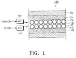
- FIG. 1 is a front view illustrating an inner surface, i.e., a surface at which a flame is discharged, of the burner 130 opposite to a quartz tube.
- the burner 130 has burner bodies 134 between burner covers 132 with hydrogen and oxygen dischargers 136 and 138 arranged between the burner bodies 134.
- the hydrogen and oxygen dischargers 136 and 138 are continuously provided with hydrogen and oxygen gas, so as to heat the surface of the second quartz tube.
- the hydrogen discharger 136 signifies an inside of each tip, while the oxygen discharger 138 signifies an outside of the tip.
- hydrogen and oxygen mass flow controllers (MFC) 140 and 142 are included, respectively, in the burner 130, for controlling a mass flow of the hydrogen and oxygen gas.
- MFC mass flow controllers
- the burner should have a size in conformity of a periphery of the second quartz tube, so as to achieve an efficient heat transfer to the inside thereof.
- a provision of a fuel such as hydrogen and oxygen gas is preferably increased to enhance a heat capacity.
- an object of the present invention to provide a process for over-cladding an optical fiber pre-form, by which a double-clad structured burner is used, so as to enlarge a hot zone on an equal basis and therefore improve a thermal efficiency as well as securing a uniform and efficient over-cladding.
- the burner heating an optical fiber pre-form includes burner covers, burner bodies positioned between the burner covers, and fuel dischargers arranged in at least two rows between the burner bodies and divided by a partition.
- the apparatus for over-cladding the optical fiber pre-form according to the present invention which performs an over-cladding on an optical fiber pre-form with a quartz tube, includes: upper and lower fixing chucks mounted on upper and lower sides of a tower; a first optic fiber pre-form having a handle rod connected to one end thereof so as to be fastened to the upper and lower fixing chucks, and having a supplementary support quartz tube connected to the other end thereof so as to be fastened to the lower fixing chuck; a second quartz tube inserted into the first optic fiber pre-form; and a hydrogen and oxygen burner including fuel dischargers including an oxygen discharger and a hydrogen discharger, at least double-clad structured and divided by a partition, thereby enlarging the hot zone in the quartz tube.
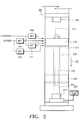
- An over-cladding apparatus for performing an over-cladding process will be described herein below with reference to FIG. 2.
- Some arrangements are installed to be vertically separated from each other around the axis of a tower 20.
- Upper and lower fixing chucks 212 and 222 are included in the over-cladding apparatus to fix a first quartz tube as a first pre-form 216 and a second pre-form 222 around the axis at the upper and lower sides of the tower 20.
- the first pre-form 216 having a handle rod 214 is installed by fixing the handle rod 214 to the upper chuck 212.
- a second quartz tube 226 having a supplementary support quartz tube 224 is installed by fixing the supplementary support quartz tube 224 to the lower fixing chuck 222. During the process, it does not matter that an installation order of the first pre-form 216 and the second quartz tube 226 is reversed.
- an upper head stock having the first pre-form 216 or a lower tail stock having the second quartz tube 226 is vertically moved so that the first pre-form 216 is inserted into the inside of the second quartz tube 226 along the axis to a moderate deepness.
- a burner 230 as a heat source is moved to the upper side of the second quartz tube 226 to heat the surface of the second quartz tube 226.
- the burner is moved downward (in an arrow direction) to eliminate the gap between the first pre-form 216 and the second quartz tube 226, continuously executing the sealing as moving downward.
- the accomplished second pre-form has been cut and separated from the upper and lower fixing chucks 212 and 222, finishing all operations.
- the burner should have a size in conformity of a periphery of the second quartz tube 226, so as to achieve an efficient heat transfer to the inside thereof.
- a fuel such as hydrogen and oxygen gas
- a vacuum pump 250 is preferably used to improve inhalation of air, serving to enhance the heat transfer efficiency.
- a burner 230 includes: a double-clad structured fuel dischargers, namely tip lines, which include an oxygen discharger 234 and a hydrogen discharger 233; pipe arrangements mounted on the respective tip lines, for providing the fuel like hydrogen and oxygen gas on an independent basis; and mass flow controllers, i.e., flow meters, installed on an independent basis, for controlling a mass flow.
- a double-clad structured fuel dischargers namely tip lines, which include an oxygen discharger 234 and a hydrogen discharger 233
- pipe arrangements mounted on the respective tip lines, for providing the fuel like hydrogen and oxygen gas on an independent basis
- mass flow controllers i.e., flow meters, installed on an independent basis, for controlling a mass flow.
- the high efficiency burner for over-cladding comprises: burner bodies 232 arranged between the upper and lower burner covers 231, respectively; tip lines featured arranged in at least two rows between the burner bodies 232; and a partition 235 positioned between the tip lines.
- the hydrogen discharger 233 signifies an inside of each tip, while the oxygen discharger 234 signifies a periphery of the tip.
- the tip lines may have hydrogen flow controllers 240 and 241 and oxygen flow controllers 242 and 243 on an independent basis. Further, the mass flow controllers are independently installed.
- a stream path, through which cooling water can flow, may be formed in the inside of the burner bodies 232 in order to prolong a durability of the burner by absorbing the heat.
- the mass flow controllers 240, 241, 242 and 243 are usually the most preferable elements to enable a fine control of the mass flow including gas.
- a flow meter, a valve and the like may be used in lieu of the mass flow controller to control the amount of flow.
- the fuel such as oxygen and hydrogen gas
- the fuel is provided through the respective independent flow controllers to upper and lower ends of burner tip lines.
- the provided fuel generates a flame on the upper and lower ends of the burner tip lines as well as heating and condensing the surface of a quartz tube 226. Since the fuel is provided through the respective independent tip lines, the provided flow is uniform. Since only a specific point is not heated, therefore, the hot zone may be enlarged far away on a uniform basis.
- the hot zone is desired to be narrow when sealing the top or cutting the bottom of the quartz tube 226.
- just one of the upper and lower ends of the burner 230 needs to be used, thereby achieving an easier control of the process.
- the high efficiency burner to be applied according to the present invention is not limited to the over-cladding apparatus, and is also used in fabricating the first optical fiber pre-form or drawing the optical fiber.
- fuel dischargers in the burner are double-clad structured having an upper side and a lower side to enable an even extending of the hot zone, to achieve a uniformity of the over-cladding as well as enhancing productivity thanks to a resultant reduction of the processing time.
- a narrow hot zone during sealing the top or cutting the bottom of the quartz tube one end of the burner tip lines is only used, thereby improving an easiness in the course of processing.
- a cooling water path may be formed between the upper and lower ends of the burner tip lines to reduce a combustibility of the burner tips due to the high temperature, and further to prolong the durability of the burner.
Landscapes
- Engineering & Computer Science (AREA)
- Chemical & Material Sciences (AREA)
- Materials Engineering (AREA)
- Organic Chemistry (AREA)
- Life Sciences & Earth Sciences (AREA)
- General Life Sciences & Earth Sciences (AREA)
- Geochemistry & Mineralogy (AREA)
- Manufacturing & Machinery (AREA)
- Combustion & Propulsion (AREA)
- Mechanical Engineering (AREA)
- General Engineering & Computer Science (AREA)
- Physics & Mathematics (AREA)
- General Physics & Mathematics (AREA)
- Optics & Photonics (AREA)
- Gas Burners (AREA)
- Manufacture, Treatment Of Glass Fibers (AREA)
- Glass Melting And Manufacturing (AREA)
Abstract
Description
Claims (12)
- A high efficiency burner for over-cladding, which heats an optical fiber pre-form, said burner (230) comprising:burner covers (231);burner bodies (232)arranged between the burner covers (231); andfuel dischargers (233, 234) arranged between said burner bodies (232) in at least two rows and being divided by a partition (235).
- The high efficiency burner according to Claim 1, wherein the burners bodies (232) are operable independently of each other.
- The high efficiency burner according to Claim 1, further comprising individual mass flow controllers (240, 241, 242, 243) for controlling a flow of gas to each respective row of said fuel dischargers (233, 234).
- The high efficiency burner according to Claim 3, wherein each individual mass flow controller (240, 241, 242, 243) is operable independently.
- The high efficiency burner according to Claim 1, wherein the mass flow of gas is oxygen and hydrogen gas.
- The high efficiency burner for over-cladding of Claim 1, wherein the mass flow of gas is LPG or butane gas.
- The high efficiency burner for over-cladding of Claim 1, wherein the fuel dischargers include an oxygen discharger (234) and a hydrogen discharger (233).
- An apparatus for over-cladding a large diameter optical fiber pre-form, which performs an over-cladding on an optical fiber pre-form with a quartz tube, comprising:upper and lower fixing chucks (212, 222) mounted on respective upper and lower sides of a tower (20);a handle rod (214) connected at a first end to the upper fixing chuck (222);a first optical fiber pre-form (216) being connected at one end to a second end of the handle rod (214) so,a supplementary support quartz tube (224) connected at a first end to the lower fixing chuck (212) and connected at a second end connected to another end of the first optical fiber pre-form (216);a second quartz tube (226) inserted into the first optical fiber pre-form (216); anda burner (230) arranged between the second end of the handle rod (214) and the lower fixing chuck (212), said burner (230) comprising at least two rows of fuel dischargers including an oxygen discharger (234) and a hydrogen discharger (233), and said at least two rows of fuel dischargers (233, 234) being divided by a partition (235).
- The apparatus as recited in claim 8, wherein respective ends of the burner (230) are operable independently when sealing a top or cutting a bottom of the second quartz tube (226).
- The apparatus according to claim 8, wherein each row of fuel dischargers (233, 234) includes an individual mass flow controller (240, 241, 242, 243).
- The apparatus as recited in claim 10, wherein the individual mass flow controllers (240 241, 242, 243) are operable on an independent basis, respectively.
- The apparatus recited in claim 10, wherein the individual mass flow controllers (240, 241, 242, 243) are flow meters.
Applications Claiming Priority (2)
| Application Number | Priority Date | Filing Date | Title |
|---|---|---|---|
| KR5674699 | 1999-12-10 | ||
| KR1019990056746A KR100342476B1 (en) | 1999-12-10 | 1999-12-10 | High effective over-cladding burner and large diameter optical fiber preform over-cladding apparatus using the same |
Publications (3)
| Publication Number | Publication Date |
|---|---|
| EP1106583A2 true EP1106583A2 (en) | 2001-06-13 |
| EP1106583A3 EP1106583A3 (en) | 2002-06-19 |
| EP1106583B1 EP1106583B1 (en) | 2005-03-30 |
Family
ID=19625047
Family Applications (1)
| Application Number | Title | Priority Date | Filing Date |
|---|---|---|---|
| EP00127114A Expired - Lifetime EP1106583B1 (en) | 1999-12-10 | 2000-12-11 | Burner and apparatus for over-cladding a rod pre-form with a tube for optical fibres |
Country Status (5)
| Country | Link |
|---|---|
| US (1) | US6729163B2 (en) |
| EP (1) | EP1106583B1 (en) |
| JP (1) | JP2001163630A (en) |
| KR (1) | KR100342476B1 (en) |
| DE (1) | DE60019070T2 (en) |
Families Citing this family (3)
| Publication number | Priority date | Publication date | Assignee | Title |
|---|---|---|---|---|
| KR100498923B1 (en) * | 2002-09-18 | 2005-07-04 | 삼성전자주식회사 | Method for over-jacketing an optical fiber primary preform through down-top heating process |
| US8620430B2 (en) * | 2006-06-30 | 2013-12-31 | Cardiac Pacemakers, Inc. | Selection of pacing sites to enhance cardiac performance |
| FR2913097B1 (en) * | 2007-02-26 | 2009-04-24 | Inst Francais Du Petrole | POROUS BURNER WITH HYDROGEN WITHOUT PREMIX |
Family Cites Families (19)
| Publication number | Priority date | Publication date | Assignee | Title |
|---|---|---|---|---|
| US3656925A (en) * | 1970-05-28 | 1972-04-18 | Owens Illinois Inc | Method and apparatus for joining two glass parts or articles |
| DE2546162B1 (en) * | 1975-10-15 | 1976-09-23 | Jenaer Glaswerk Schott & Gen | Optical fiber with a refractive index gradient for communication |
| US4231777A (en) | 1979-03-27 | 1980-11-04 | Western Electric Company, Inc. | Methods of and apparatus for heating a glass tube |
| US4251251A (en) * | 1979-05-31 | 1981-02-17 | Corning Glass Works | Method of making optical devices |
| US4477273A (en) | 1982-06-15 | 1984-10-16 | At&T Technologies, Inc. | Method of and apparatus for straightening and configuring a preform tube from which lightguide fiber is drawn |
| JPS59182243A (en) * | 1983-03-29 | 1984-10-17 | Fujitsu Ltd | Manufacture of optical fiber |
| US4486214A (en) * | 1983-12-08 | 1984-12-04 | At&T Technologies, Inc. | Methods of and apparatus for collapsing a preform tube into a preform from which lightguide fiber is drawn |
| US4477244A (en) | 1983-12-19 | 1984-10-16 | At&T Technologies, Inc. | Torch |
| DE3400710A1 (en) * | 1984-01-11 | 1985-07-18 | Siemens AG, 1000 Berlin und 8000 München | GAS BURNER FOR THE EXTERNAL HEATING OF GLASS BODIES |
| US4596589A (en) * | 1984-02-09 | 1986-06-24 | Perry Gregory A | Method for producing a single mode fiber preform |
| US4820322A (en) * | 1986-04-28 | 1989-04-11 | American Telephone And Telegraph Company At&T Bell Laboratories | Method of and apparatus for overcladding a glass rod |
| US5169422A (en) * | 1991-04-11 | 1992-12-08 | At&T Bell Laboratories | Methods for heating elongated glass substrate |
| KR0177088B1 (en) * | 1993-11-29 | 1999-05-15 | 김광호 | The overcladding process for the first preform of single mode optical fiber and facilities thereof |
| EP0656325B1 (en) * | 1993-11-29 | 1999-09-22 | AT&T Corp. | Method for making optical fiber preforms |
| GB2291643B (en) * | 1994-07-21 | 1998-01-28 | Pirelli General Plc | Optical fibre preforms |
| US5868815A (en) * | 1997-02-20 | 1999-02-09 | Lucent Technologies Inc. | Method of making an optical fiber by blowing on a preform tube to enhance collapse |
| US6145345A (en) * | 1998-06-05 | 2000-11-14 | Lucent Technologies Inc. | Modified chemical vapor deposition using independently controlled thermal sources |
| US6481721B1 (en) * | 1999-07-15 | 2002-11-19 | Lucent Technologies Inc. | Method and apparatus for overcladding a glass rod |
| US6460378B1 (en) * | 2000-02-29 | 2002-10-08 | Xiaoyuan Dong | Collapsing a multitube assembly and subsequent optical fiber drawing in the same furnace |
-
1999
- 1999-12-10 KR KR1019990056746A patent/KR100342476B1/en not_active Expired - Fee Related
-
2000
- 2000-12-01 JP JP2000367529A patent/JP2001163630A/en active Pending
- 2000-12-11 US US09/734,124 patent/US6729163B2/en not_active Expired - Fee Related
- 2000-12-11 EP EP00127114A patent/EP1106583B1/en not_active Expired - Lifetime
- 2000-12-11 DE DE60019070T patent/DE60019070T2/en not_active Expired - Fee Related
Also Published As
| Publication number | Publication date |
|---|---|
| US20010015081A1 (en) | 2001-08-23 |
| US6729163B2 (en) | 2004-05-04 |
| DE60019070T2 (en) | 2005-08-11 |
| DE60019070D1 (en) | 2005-05-04 |
| KR100342476B1 (en) | 2002-06-28 |
| EP1106583B1 (en) | 2005-03-30 |
| JP2001163630A (en) | 2001-06-19 |
| EP1106583A3 (en) | 2002-06-19 |
| KR20010055530A (en) | 2001-07-04 |
Similar Documents
| Publication | Publication Date | Title |
|---|---|---|
| FI77217B (en) | FOERFARANDE FOER FRAMSTAELLNING AV EN POLARISATIONSBEVARANDE OPTISK FIBER. | |
| TW476738B (en) | Large MCVD preform for singlemode fiber and method for making same | |
| KR830002158B1 (en) | Method for forming optical waveguide preform having continuously removable starting member | |
| CN102092934B (en) | Method for fabricating core rod sections useable for production of finished optical fiber | |
| EP0138512B1 (en) | Method of forming laminated single polarization fiber | |
| HK77490A (en) | Optical fiber and method for its production | |
| NO164139B (en) | OPTICAL POLARIZATION CONSERVING FIBERS OF THE SINGLE-WAVE TYPE AND PROCEDURE FOR THE PREPARATION OF AN OPTICAL FIBER BASIS. | |
| JPH11209141A (en) | Production of segment core optical waveguide preform | |
| US8820121B2 (en) | Method of manufacturing optical fiber base material | |
| EP0100174B1 (en) | Method of making glass optical fiber | |
| CN107107102B (en) | Enhanced particle deposition system and method | |
| EP1106583B1 (en) | Burner and apparatus for over-cladding a rod pre-form with a tube for optical fibres | |
| BR102012018849A2 (en) | METHODS FOR MAKING LOW WATER PEAK WAVES GUIDE | |
| KR100277358B1 (en) | Optical fiber base material manufacturing apparatus and method by chemical vapor deposition | |
| KR100288739B1 (en) | Optical preform manufacturing method | |
| CN118343992A (en) | Burner for adapting to normal pressure plasma external deposition and preparation method of fluorine-doped preform | |
| CN102690054B (en) | The method manufacturing fibre-optical preform and the method forming optical fiber | |
| US12358829B2 (en) | Method for manufacturing a preform for a multi-core optical fiber and method for manufacturing multi-core optical fibers | |
| US20050262877A1 (en) | Method of depositing glass soot | |
| US6928841B2 (en) | Optical fiber preform manufacture using improved VAD | |
| JP2003238203A (en) | Method for manufacturing quartz optical fiber and quartz optical fiber preform | |
| JP4890767B2 (en) | Manufacturing method of preform rod for optical fiber | |
| CN100999382B (en) | Method for fabricating optical fiber preform and method for fabricating optical fiber using the same | |
| JPS63156032A (en) | Formation of suit for preform | |
| CN118561512A (en) | Preparation method of three-clad optical fiber and three-clad optical fiber |
Legal Events
| Date | Code | Title | Description |
|---|---|---|---|
| PUAI | Public reference made under article 153(3) epc to a published international application that has entered the european phase |
Free format text: ORIGINAL CODE: 0009012 |
|
| 17P | Request for examination filed |
Effective date: 20001211 |
|
| AK | Designated contracting states |
Kind code of ref document: A2 Designated state(s): AT BE CH CY DE DK ES FI FR GB GR IE IT LI LU MC NL PT SE TR |
|
| AX | Request for extension of the european patent |
Free format text: AL;LT;LV;MK;RO;SI |
|
| PUAL | Search report despatched |
Free format text: ORIGINAL CODE: 0009013 |
|
| AK | Designated contracting states |
Kind code of ref document: A3 Designated state(s): AT BE CH CY DE DK ES FI FR GB GR IE IT LI LU MC NL PT SE TR |
|
| AX | Request for extension of the european patent |
Free format text: AL;LT;LV;MK;RO;SI |
|
| AKX | Designation fees paid |
Designated state(s): DE FR GB |
|
| 17Q | First examination report despatched |
Effective date: 20031112 |
|
| GRAP | Despatch of communication of intention to grant a patent |
Free format text: ORIGINAL CODE: EPIDOSNIGR1 |
|
| GRAS | Grant fee paid |
Free format text: ORIGINAL CODE: EPIDOSNIGR3 |
|
| GRAA | (expected) grant |
Free format text: ORIGINAL CODE: 0009210 |
|
| AK | Designated contracting states |
Kind code of ref document: B1 Designated state(s): DE FR GB |
|
| REG | Reference to a national code |
Ref country code: GB Ref legal event code: FG4D |
|
| REF | Corresponds to: |
Ref document number: 60019070 Country of ref document: DE Date of ref document: 20050504 Kind code of ref document: P |
|
| REG | Reference to a national code |
Ref country code: IE Ref legal event code: FG4D |
|
| PGFP | Annual fee paid to national office [announced via postgrant information from national office to epo] |
Ref country code: DE Payment date: 20060120 Year of fee payment: 6 |
|
| PLBE | No opposition filed within time limit |
Free format text: ORIGINAL CODE: 0009261 |
|
| STAA | Information on the status of an ep patent application or granted ep patent |
Free format text: STATUS: NO OPPOSITION FILED WITHIN TIME LIMIT |
|
| ET | Fr: translation filed | ||
| 26N | No opposition filed |
Effective date: 20060102 |
|
| PGFP | Annual fee paid to national office [announced via postgrant information from national office to epo] |
Ref country code: GB Payment date: 20061206 Year of fee payment: 7 |
|
| PG25 | Lapsed in a contracting state [announced via postgrant information from national office to epo] |
Ref country code: DE Free format text: LAPSE BECAUSE OF NON-PAYMENT OF DUE FEES Effective date: 20070703 |
|
| PGFP | Annual fee paid to national office [announced via postgrant information from national office to epo] |
Ref country code: FR Payment date: 20071210 Year of fee payment: 8 |
|
| GBPC | Gb: european patent ceased through non-payment of renewal fee |
Effective date: 20071211 |
|
| PG25 | Lapsed in a contracting state [announced via postgrant information from national office to epo] |
Ref country code: GB Free format text: LAPSE BECAUSE OF NON-PAYMENT OF DUE FEES Effective date: 20071211 |
|
| REG | Reference to a national code |
Ref country code: FR Ref legal event code: ST Effective date: 20090831 |
|
| PG25 | Lapsed in a contracting state [announced via postgrant information from national office to epo] |
Ref country code: FR Free format text: LAPSE BECAUSE OF NON-PAYMENT OF DUE FEES Effective date: 20081231 |