EP1106552A2 - Coat film transfer head device and coat film transfer tool - Google Patents
Coat film transfer head device and coat film transfer tool Download PDFInfo
- Publication number
- EP1106552A2 EP1106552A2 EP00310625A EP00310625A EP1106552A2 EP 1106552 A2 EP1106552 A2 EP 1106552A2 EP 00310625 A EP00310625 A EP 00310625A EP 00310625 A EP00310625 A EP 00310625A EP 1106552 A2 EP1106552 A2 EP 1106552A2
- Authority
- EP
- European Patent Office
- Prior art keywords
- coat film
- film transfer
- head
- head body
- head device
- Prior art date
- Legal status (The legal status is an assumption and is not a legal conclusion. Google has not performed a legal analysis and makes no representation as to the accuracy of the status listed.)
- Withdrawn
Links
Images


Classifications
-
- B—PERFORMING OPERATIONS; TRANSPORTING
- B43—WRITING OR DRAWING IMPLEMENTS; BUREAU ACCESSORIES
- B43L—ARTICLES FOR WRITING OR DRAWING UPON; WRITING OR DRAWING AIDS; ACCESSORIES FOR WRITING OR DRAWING
- B43L19/00—Erasers, rubbers, or erasing devices; Holders therefor
-
- B—PERFORMING OPERATIONS; TRANSPORTING
- B65—CONVEYING; PACKING; STORING; HANDLING THIN OR FILAMENTARY MATERIAL
- B65H—HANDLING THIN OR FILAMENTARY MATERIAL, e.g. SHEETS, WEBS, CABLES
- B65H37/00—Article or web delivery apparatus incorporating devices for performing specified auxiliary operations
- B65H37/002—Web delivery apparatus, the web serving as support for articles, material or another web
- B65H37/005—Hand-held apparatus
- B65H37/007—Applicators for applying coatings, e.g. correction, colour or adhesive coatings
-
- B—PERFORMING OPERATIONS; TRANSPORTING
- B65—CONVEYING; PACKING; STORING; HANDLING THIN OR FILAMENTARY MATERIAL
- B65H—HANDLING THIN OR FILAMENTARY MATERIAL, e.g. SHEETS, WEBS, CABLES
- B65H2403/00—Power transmission; Driving means
- B65H2403/60—Damping means, shock absorbers
Definitions
- the present invention relates to a coat film transfer head device and a coat film transfer tool, and more particularly, coat film transfer head techniques wherein a coat film transfer head is mounted at the tip of a film transfer tool to transfer coat film such as a correction paint layer, marker paint layer, and adhesive layer of a coat film transfer tape onto paper or the like, and is operated to press the coat film transfer tape against a coat film transferring surface.
- a coat film transfer head is mounted at the tip of a film transfer tool to transfer coat film such as a correction paint layer, marker paint layer, and adhesive layer of a coat film transfer tape onto paper or the like, and is operated to press the coat film transfer tape against a coat film transferring surface.
- a coat film transfer tool of this type is used, for example, as a character eraser to correct wrong characters.
- a general structure is such that an unwinding reel with coat film transfer tape wound thereon and a winding reel to recover the used coat film transfer tape are rotatably disposed in a case which may be held and operated by one hand, and at the same time, a coat film transfer head used to press the coat film transfer tape against a coat film transferring surface or a portion to be corrected on paper is mounted at the tip of the case in projecting fashion. Also, the reels are interlocked with each other by means of an interlock unit, employing an automatic winding system.
- the head is generally designed to be suited for precise erasure and correction of the intended portion to be corrected, for example, a small area portion such as only one wrong character in a series of sentences, that is, the tip of the head is to be a so-called spire shape having a relatively sharp edge.
- a structure recently proposed and employed is such that a head cover to protect the head is attached in a removable or free-to-open fashion to the case of a coat film transfer tool.
- such structure causes an increase in the number of parts used and in production cost that will further invite an increase in product cost, and also, in the case of a removable head cover, there is a fear of missing of the removed cover, and in the case of a free-to-open cover, the cover being open can be an obstruction in practical use, thus remaining some room for further improvement from the viewpoint of a drastic solution of the above problem.
- a primary object of the present invention is to provide a novel coat film transfer head device that has solved such conventional problem.
- Another object of the present invention is to provide a coat film transfer head device having a structure such that no protective member such as a head cover is needed and, even when strong shocks are applied to the head, the shocks will be effectively absorbed, thereby reliably preventing the head from damage and the coat film transfer tape from breakage.
- a further object of the present invention is to provide a coat film transfer tool comprising the coat film transfer head device.
- Still another object of the present invention is to provide a coat film transfer tool comprising a structure such that, in a refill type of the above device, the transfer tool is laterally slidable in practical use.
- a coat film transfer head device of the present invention is such that the head device disposed at the tip of a coat film transfer tool is designed to transfer a coat film transfer tape unwound from an unwinding reel onto a coat film transferring surface, comprising a shock absorbing means to absorb shocks applied to the head body which serves the function of pressing and transferring the coat film transfer tape.
- shock absorbing means As a preferred embodiment of the above shock absorbing means, the following will be adopted according to the purpose:
- shock absorbing means are applicable to any types of head devices such as what is called a rotary head type having a rotary head structure wherein the body support mounted at the head retainer is rotatable about its axis and a so-called stationary head type wherein the body support mounted at the head retainer is stationary.
- a coat film transfer tool of the present invention comprises the coat film transfer head device, wherein a tape cartridge having a rotatable unwinding reel with a coat film transfer tape wound thereon and a rotatable winding reel to recover the used coat film transfer tape is removably inserted in a case that can be held and operated by one hand, and in a refill type which permits the replacement of the coat film transfer tape, the coat film transfer head device is mounted at the tip of the tape cartridge or at the tip of the case.
- the coat film transfer head device is mounted at the tip of the case.
- a shock absorbing means to absorb shocks applied to the head body that serves to press and transfer a coat film transfer tape so that even when the coat film transfer tool is dropped during one-handed operation or transport, causing strong shocks to the head, such shocks will be absorbed by the shock absorbing means, thereby reliably preventing trouble such as damage to the tip pressure piece of the head having a sharp-edge shape or breakage of the coat film transfer tape by the tip pressure piece.
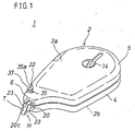
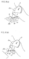
- Fig. 1 is a perspective view of a character eraser in accordance with embodiment 1 of the present invention.
- Fig. 2 is a perspective view of the interior of a case body of the character eraser.
- Fig. 3 is an exploded perspective view of the character eraser.
- Fig. 4 (a) is a perspective view of a head body comprising a shock absorbing structure that is an essential part of a coat film transfer head device of the character eraser.
- Fig. 4 (b) is a plan view of the head body.
- Fig. 4 (c) is a side view of the head body.
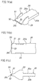
- Fig. 5 is an enlarged side view showing a partial cross-section of the rotary structure of a coat film transfer head device of the character eraser.
- Fig. 6 is a perspective view showing the character eraser being used by right hand in a state of lateral pull-slide motion.
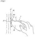
- Fig. 7 is a perspective view showing the character eraser being used by right hand in a state of vertical pull-slide motion.
- Fig. 8 is a perspective view showing the character eraser being used by right hand in a state of lateral push-slide motion.
- Fig. 9 is a perspective view showing the character eraser being used by left hand in a state of lateral pull-slide motion.
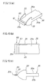
- Fig. 10 (a) is a perspective view of a head body comprising a shock absorbing structure that is an essential part of a coat film transfer head device of the character eraser in accordance with embodiment 2 of the present invention.
- Fig. 10 (b) is a plan view of the head body.
- Fig. 10 (c) is a side view of the head body.
- Fig. 11 (a) is a perspective view of a head body comprising a shock absorbing structure that is an essential part of a coat film transfer head device of the character eraser in accordance with embodiment 3 of the present invention.
- Fig. 11 (b) is a plan view of the head body.
- Fig. 11 (c) is a side view of the head body.
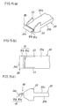
- Fig. 12 (a) is a perspective view of a head body comprising a shock absorbing structure that is an essential part of a coat film transfer head device of the character eraser in accordance with embodiment 4 of the present invention.
- Fig. 12 (b) is a plan view of the head body.
- Fig. 12 (c) is a side view of the head body.
- Fig. 13 (a) is a perspective view of a head body comprising a shock absorbing structure that is an essential part of a coat film transfer head device of the character eraser in accordance with embodiment 5 of the present invention.
- Fig. 13 (b) is a plan view of the head body.
- Fig. 13 (c) is a side view of the head body.
- Fig. 14 (a) is a perspective view of a head body comprising a shock absorbing structure that is an essential part of a coat film transfer head device of the character eraser in accordance with embodiment 6 of the present invention.
- Fig. 14 (b) is a plan view of the head body.
- Fig. 14 (c) is a side view of the head body.
- Fig. 15 (a) is a perspective view of a head body comprising a shock absorbing structure that is an essential part of a coat film transfer head device of the character eraser in accordance with embodiment 7 of the present invention.
- Fig. 15 (b) is a plan view of the head body.
- Fig. 15 (c) is a side view of the head body.
- Fig. 16 (a) is a perspective view of a head body comprising a shock absorbing structure that is an essential part of a coat film transfer head device of the character eraser in accordance with embodiment 8 of the present invention.
- Fig. 16 (b) is a plan view of the head body.
- Fig. 16 (c) is a side view of the head body.
- Fig. 17 (a) is a perspective view of a head body comprising a shock absorbing structure that is an essential part of a coat film transfer head device of the character eraser in accordance with embodiment 9 of the present invention.
- Fig. 17 (b) is a plan view of the head body.
- Fig. 17 (c) is a side view showing an enlarged shock absorbing structure of the head body.
- Fig. 18 (a) is a perspective view of a head body comprising a shock absorbing structure that is an essential part of a coat film transfer head device of the character eraser in accordance with embodiment 10 of the present invention.
- Fig. 18 (b) is a plan view of the head body.
- Fig. 18 (c) is a side view of the head body.
- Fig. 19 (a) is a perspective view of a head body comprising a shock absorbing structure that is an essential part of a coat film transfer head device of the character eraser in accordance with embodiment 11 of the present invention.
- Fig. 19 (b) is a plan view of the head body.
- Fig. 19 (c) is a side view showing an enlarged shock absorbing structure of the head body.
- Fig. 20 (a) is a perspective view of a head body comprising a shock absorbing structure that is an essential part of a coat film transfer head device of the character eraser in accordance with embodiment 12 of the present invention.
- Fig. 20 (b) is a plan view of the head body.
- Fig. 20 (c) is a side view of the head body.
- Fig. 21 (a) is a perspective view of a head body comprising a shock absorbing structure that is an essential part of a coat film transfer head device of the character eraser in accordance with embodiment 13 of the present invention.
- Fig. 21 (b) is a plan view of the head body.
- Fig. 21 (c) is a side view of the head body.
- Fig. 22 (a) is a perspective view of a head body comprising a shock absorbing structure that is an essential part of a coat film transfer head device of the character eraser in accordance with embodiment 14 of the present invention.
- Fig. 22 (b) is a plan view of the head body.
- Fig. 22 (c) is a side view of the head body.
- Fig. 23 (a) is a perspective view of a head body comprising a shock absorbing structure that is an essential part of a coat film transfer head device of the character eraser in accordance with embodiment 15 of the present invention.
- Fig. 23 (b) is a plan view of the head body.
- Fig. 23 (c) is an enlarged sectional diagram along C - C line of Fig. 23 (b) of the head body.
- Fig. 23 (d) is an enlarged sectional diagram along D - D line of Fig. 23 (b) of the head body.
- Fig. 24 (a) is a perspective view of a head body comprising a shock absorbing structure that is an essential part of a coat film transfer head device of the character eraser in accordance with embodiment 16 of the present invention.
- Fig. 24 (b) is a plan view of the head body.
- Fig. 24 (c) is an enlarged sectional diagram along C - C line of Fig. 24 (b) of the head body.
- Fig. 24 (d) is an enlarged sectional diagram along D - D line of Fig. 24 (b) of the head body.
- Fig. 25 (a) is a perspective view of a head body comprising a shock absorbing structure that is an essential part of a coat film transfer head device of the character eraser in accordance with embodiment 17 of the present invention.
- Fig. 25 (b) is a plan view of the head body.
- Fig. 25 (c) is an enlarged sectional diagram along C - C line of Fig. 25 (b) of the head body.
- Fig. 26 (a) is a perspective view of a head body comprising a shock absorbing structure that is an essential part of a coat film transfer head device of the character eraser in accordance with embodiment 18 of the present invention.
- Fig. 26 (b) is a plan view of the head body.
- Fig. 26 (c) is an exploded enlarged perspective view of a shock absorbing structure of the head body.
- Fig. 27 (a) is a perspective view of a head body comprising a shock absorbing structure that is an essential part of a coat film transfer head device of the character eraser in accordance with embodiment 19 of the present invention.
- Fig. 27 (b) is a plan view of the head body.
- Fig. 27 (c) is an enlarged sectional diagram along C - C line of Fig. 27 (b) of the head body.
- Fig. 27 (d) is an enlarged sectional diagram along D - D line of Fig. 27 (b) of the head body.
- Fig. 28 (a) is a perspective view of a head body comprising a shock absorbing structure that is an essential part of a coat film transfer head device of the character eraser in accordance with embodiment 20 of the present invention.
- Fig. 28 (b) is a plan view of the head body.
- Fig. 28 (c) is an enlarged sectional diagram along C - C line of Fig. 28 (b) of the head body.
- Fig. 28 (d) is an enlarged sectional diagram along D - D line of Fig. 28 (b) of the head body.
- Fig. 29 (a) is a perspective view of a head body comprising a shock absorbing structure that is an essential part of a coat film transfer head device of the character eraser in accordance with embodiment 21 of the present invention.
- Fig. 29 (b) is a plan view of the head body.
- Fig. 29 (c) is an enlarged sectional diagram along C - C line of Fig. 29 (b) of the head body.
- Fig. 30 is an exploded perspective view of a tape cartridge of a character eraser in accordance with embodiment 22 of the present invention.
- Fig. 31 is an exploded perspective view of a character eraser in accordance with embodiment 23 of the present invention.
- Fig. 32 is an exploded perspective view of a character eraser in accordance with embodiment 24 of the present invention.
- Fig. 1 ⁇ Fig. 32 are shown a coat film transfer head device and a coat film transfer tool embodying the present invention, and the same numerals used throughout the drawings stand for the same component members or elements.
- a coat film transfer tool in accordance with this embodiment is shown in Fig. 1 ⁇ Fig. 4.
- the coat film transfer tool 1 is designed to be used as a character eraser to correct wrong characters or the like, which comprises a cartridge or refill type structure wherein coat film transfer tape T is replaceable as a consumable part.
- the coat film transfer tool 1 is such that a tape cartridge C having a coat film transfer head device H as shown in Fig. 2 and Fig. 3 is disposed in a case 2 whose appearance is shown in Fig. 1, and the coat film transfer head device H comprises a shock absorbing structure (shock absorbing means) 3.
- the case 2 is a flat box, as shown, having front contour shape and widthwise dimensions enough to incorporate a tape cartridge C, and a pair of opposing flat face and back surfaces 2a, 2b are standard grip surfaces to be held during one-handed operation.
- the case 2 is made of plastic and is rigidly molded by injection molding or the like, having a structure such that case body 4 and cap body 5 can be separated from each other and the tape cartridge C is removably inserted in the case body 4. Also, at the tip of the case 2 is formed a head insertion port 6 where coat film transfer head device H is disposed in projecting fashion.
- the tape cartridge C is a component part that is replaceable as a consumable part.
- the structure of the tape cartridge C is such that an unwinding reel 11 with coat film transfer tape T wound thereon and a rotatable winding reel 12 to recover the used coat film transfer tape T are rotatably inserted in cartridge case 10, and the coat film transfer head device H which presses the coat film transfer tape T against a coat film transferring surface is disposed and rotatable about the head axis.
- the tape cartridge 10 is furnished, in the form of a unit, with a tape interlock unit to interlock the unwinding reel 11 and the winding reel 12 with each other as well as major basic components such as a clutch mechanism to synchronize the unwinding and winding speeds of the coat film transfer tape T on the unwinding reel 11 and winding reel 12.
- the cartridge case 10 is made of synthetic resin in the form of a cartridge to store both reels 11 and 12, wherein the shape and dimension are determined so as to make the case as light-weight and compact as possible provided that the reels 11 and 12 maybe reliably stored, specifically having a framework structure made up mostly of thin framework members.
- coat film transfer tape T a conventionally well-known type has a structure such that a release agent layer, correction paint layer, and adhesive (pressure sensing adhesive) are laminated in order on one side of a film base.
- the correction paint layer employed is what is called a dry type that permits writing thereon immediately after coat film transfer.
- the coat film transfer tape T unwound from the unwinding reel 11 is guided to the tip pressure piece 20c along the tape traveling surface at one side of the coat film transfer head device H and then the tape T is reversed via the tip pressure piece 20c and is further guided along the tape traveling surface at the other side to be taken up onto the winding reel 12.
- the coat film transfer head device H serves to press the coat film transfer tape T against the portion to be corrected (coat film transferring surface) such as a wrong character or the like on paper, which is located at the tip of the cartridge case 10 and has a function to guide as well as a function to press the coat film transfer tape T.
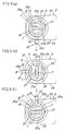
- the coat film transfer head device H comprises head body 20, head support 21 and rotary control 22, and also a so-called rotary head structure wherein the head body 20 is supported and rotatable about its axis. Also, the coat film transfer head device H comprises, as described above, the shock absorbing structure 3 (see Fig. 4) which absorbs the shocks applied to the head body 20.
- the head body 20 serves to press and transfer the coat film transfer taper T and has a shape suited for precisely correcting the intended portion to be corrected, for example, a small area portion such as only one wrong character in a series of sentences, that is, a so-called spire shape having a relatively sharp edge.
- the head body 20 of the embodiment shown in the drawing is of thin plate type having a rectangular shape a little wider than the coat film transfer tape T and is relatively sharp as viewed from the side or has a tapered cross-section that is gradually reduced in thickness toward the tip.
- the head body 20 has flat side surfaces 20a, 20b as tape traveling surfaces, and the tip 20c is a tip pressure piece that applies pressures to the coat film transfer tape T.
- guide flanges 23, 23 to guide the coat film transfer tape T are formed at the side edges of the head body 20.
- the head body 20 when the head body 20 is relatively less in plate thickness, it is not always necessary to make the shape tapered as shown, but permitted to make the shape being equal in thickness over the entire body in the lengthwise direction. In other words, it is enough for the structure to have a thickness (sharpness) such that the tip pressure piece 20c of the head body 20 may precisely function to erase and correct only one wrong character in a series of sentences.
- the head body 20 has at its tip the shock absorbing structure 3, and at the base end portion is formed a journal 25 as a body support in one piece with the head body.
- the shock absorbing structure 3 is such that a shock absorber 30 made up of elastic material different from the plastic base material of the head body 20 is connected in one piece with a part of the head body.
- the shock absorber 30 of the embodiment shown is connected in one piece with the tip of the head body 20 during or after head molding, thereby forming a head tip edge or the tip pressure piece 20c that presses the coat film transfer tape T.
- shock absorber 30 As a component material of shock absorber 30, it is required not only to have a substantial function as a suitable shock absorbing material but also to be able to secure a pressing function as a tip pressure piece 20c, for example, it is preferred to use soft plastic, thermoplastic elastomer or rubber which is excellent in softness. In the embodiment shown, shock absorber 30 made up of such material is connected, for example, by two-color molding in one piece with the base material of head body 20.
- shock absorber 30 shown is band-shaped having a specific width parallel to the tip pressure piece 20c, but it is not always necessary to have such shape, and for example, a structure having irregular connecting surfaces may be employed in order to improve the strength of connection with the base material of the head body.
- the shock absorbing structure 3 may be rigidly connected to the tip of head body 20 as shown or when the tip of head body 20 is formed of base material, forming the base of the tip, the shock absorbing structure may be connected in one piece with a part of head body 20 to obtain an absorbing effect.
- a component material of shock absorber 30 which has a substantial function as a suitable shock absorbing material may be employed.
- Head retainer 21 serves to support the head body 20 in a manner such that the head body is rotatable about its axis.
- the head retainer comprises a journal 25, which supports the head body, and a bearing 26 located in cartridge case 10.
- Journal 25, as shown in Fig. 4 and Fig. 5, is cylindrical in shape being concentric and in one-piece with head body 20. Specifically, the journal is circular cross-sectional in shape partially having an opening 25a for setting coat film transfer tape T onto head body 20.
- Bearing 26 is disposed in one piece with the tip of cartridge case 10.
- the bearing 26, as shown in Fig. 5, is cylindrical in shape having a inner periphery in response to the outer periphery of the journal 25, and the same as in journal 25, the bearing is circular cross-sectional in shape partially having an opening 26a for setting coat film transfer tape T onto head body 20.
- the journal 25 is slidably and rotatably supported on the bearing 26, and the head body 20 is free to rotate about its axis within the range of the specified angle of rotation described later.
- Rotary control 22 serves to determine the position of head body 20 in the rotational direction and is also used as a head position indicator that indicates the tape press-transfer position of the head body 20.
- the rotary control 22 is a cylindrical rod comprising as an essential part an operation lever 35 having an operation knob 35a at the tip.
- the operation lever 35 extends linearly and outwardly in the direction of diameter from the axis of journal 25 and is projected outwardly of case 2 through slit insertion port 36 and operation guide 37 which are respectively located in the corresponding positions of bearing 26 and case 2.
- the insertion port 36 of the bearing 26 also functions to prevent the head body 20 from slipping off in the axial direction.
- the position of the operation lever 35 in the rotational direction to the head body 20 is determined in relation to the tape press-transfer position of the head body 20, while the insertion port 36 and operation guide 37 are disposed extending in a peripheral direction to permit the movement of operation lever 35 in the axial direction of head body 20.
- the operation guide 37 of case 2 serves to define the operation of the operation lever 35 in the axial direction and to control the tape press-transfer position of the head body 20.
- the head body 20 of coat film transfer head device H is at a guiding angle position so that the tip pressure piece 20c keeps the coat film transfer tape T nearly opposite to grip surfaces 2a, 2b of case 2, that is, the face and back surfaces of coat film transfer tape T are positioned nearly identical (parallel) in direction with the grip surfaces 2a, 2b.
- the new coat film transfer tape T unwound from unwinding reel 11 is located at the lower side of the head body 20, which is in a state suited for use in lateral pull-slide motion by a right-handed person, for example, to correct a part of European writing.
- the operation lever 35 is in an intermediate position between the ends 37a, 37b of the operation guide 37 or in a horizontal position [second defining position B shown in Fig.
- the head body 20 of coat film transfer head device H is at a guiding angle position so that the tip pressure piece 20c keeps the coat film transfer tape T in the winding position of unwinding reel 11 and winding reel 12, that is, the face and back surfaces of coat film transfer tape T are nearly vertical (orthogonal) to the grip surfaces 2a, 2b.
- the new coat film transfer tape T unwound from the unwinding reel 11 is located at the left side of the head body 20, which is in a state suited for use in vertical pull-slide motion, for example, to correct a part of Japanese writing.
- the operation lever 35 is in engagement with the other end 37b of operation guide 37 or in a vertical upward position [third defining position C shown in Fig. 5 (c)]
- the head body 20 of coat film transfer head device H is at a guiding angle position so that, in an upside-down position of (a), the tip pressure piece 20c keeps the coat film transfer tape T nearly opposite to the face and back surfaces 2a, 2b.
- the new coat film transfer tape T unwound from the unwinding reel 11 is located at the upper side of the head body 20, which is in a state suited for use in lateral push-slide motion by a right-handed person, for example, to correct a part of European writing (see Fig. 8) or in a state suited for use in lateral pull-slide motion by a left-handed person, for example, to correct a part of European writing (see Fig. 9).
- the position of the operation lever 35 directly and visually indicates the facing direction of the new coat film transfer tape T (a function as a head position indicator), and the user is able to check the tape press-transfer position of the head body 20 by observing the position of the operation lever 35.
- the operation range in the rotational direction of operation guide 37 may be set to various values in a range from small to large angles, taking into account the relationship between the operation lever 35 and the tape press-transfer position of head body 20.
- a coat film transfer tool 1 having a configuration as described may be used in various ways as shown in Fig. 6 ⁇ Fig. 9 for example to correct wrong characters or the like, irrespective of right-handed or left-handed persons, by manipulating the operation lever 35 according to the purpose to select and set the optimum tape press-transfer position of head body 20 of coat film transfer head device H [typically, the first defining position A in Fig. 5 (a), second defining position B in Fig. 5 (b), third defining position C in Fig. 5 (c)] and by holding the grip surfaces of case 2 (standard grip surfaces are face and back surfaces 2a, 2b, but any suitable portions or surfaces of case 2 may be gripped according to the purpose) in relation to the selected transfer position.
- standard grip surfaces are face and back surfaces 2a, 2b, but any suitable portions or surfaces of case 2 may be gripped according to the purpose
- the case 2 is held by hand the same as in holding a writing tool, then the tip pressure piece 20c of coat film transfer head device H is pressed tight against the starting end of the portion to be corrected (coat film transferring surface) 40 on paper for example to correct a wrong character or the like and the case 2 is immediately moved along the paper or the like and then stopped at the end (right-hand end) of the portion to be corrected 40.
- correction paint layer (white) 41 of coat film transfer tape T at the tip pressure piece 20c of the coat film transfer head device H has been transferred, coming off the film base material, onto the portion to be corrected 40. In this way, a wrong character or the like will be erased and it is then possible to write a correct character thereon.
- the head body 20 of coat film transfer head device H is free to rotate about its axis although it is based on the tape press-transfer position predetermined by operation lever 35, and it is possible to make a correction, with respect to a curved portion as in a diagram, precisely along the curve as shown in Fig. 6 (b), Fig. 8 (b) or Fig. 9 (b) as well as linear portions such as a string of characters.
- shock absorber 30 of shock absorbing structure 3 disposed at the tip of head body 20, reliably preventing the tip pressure piece 20c of head body 20 from damage or coat film transfer tape T from being broken by the tip pressure piece 20c.
- Fig. 10 (a) ⁇ Fig. 10 (c), which includes some modifications with respect to the specific structure of coat film transfer head device H in embodiment 1.
- shock absorber 30 is connected in one piece with only the tip of head body 20, while in the coat film transfer head device H of this embodiment, shock absorbers 41 of shock absorbing structure 40 are connected at a plurality of portions in on piece with the base material section of head body 20 alternately in the lengthwise direction.
- shock absorbers 41 are connected in one piece with the tip of head body 20 the same as in embodiment 1 and also with the base material of head body 20 at a plurality of portions (3 portions in the illustration) alternately in the lengthwise direction.
- elastic material different from plastic that is the base material of head body 20 is employed the same as in embodiment 1, for example, it is preferred to use soft plastic, thermoplastic elastomer or rubber being excellent in softness.
- the shock absorber 30 of the embodiment illustrated is connected, by two-color molding for example, in one piece with the base material of head body 20.
- shock absorbing structure 3 such that the shock absorbers are alternately connected in one piece with the base material of head body 20 or the tip of head body 20 is formed of base material and the base of the tip is of shock absorbing material (elastic material), and the shock absorbers are alternately connected in one piece with the tip and the base material at a plurality of portions in the lengthwise direction.
- the head body 20 of coat film transfer head device H is provided with a greater shock absorbing function and also the entire tip portion of head body 20 is given appropriate elasticity.
- Fig. 11 (a) ⁇ Fig. 11 (c), which includes some modifications with respect to the specific structure of coat film transfer head device H.
- the shock absorbing structure (shock absorbing means) 50 in coat film transfer head device H of this embodiment is such that shock absorber 51 made up of elastic material different from the base material of head body 20 is removably mounted at the tip of head body 20, and a part of the shock absorber 51 forms a head tip edge for press-transfer of coat film transfer tape T or head tip pressure piece 20c.
- the shock absorber 51 is, same as in embodiment 1, made up of elastic material different from plastic that is the base material of the head body 20 is naturally required to be substantially suitable as a shock absorbing material and able to secure a pressing function as tip pressure piece 20c, for example, using soft plastic, thermoplastic elastomer or rubber being excellent in softness as a material.
- the shock absorber 51 is rhombic in cross-section and symmetrical with respect to front and back as illustrated, and each tip of the rhombus forms the tip pressure piece 20c.
- a retaining groove 52 having a cross-section corresponding to that of the shock absorber 51 which is retained in the groove 52 and is removable sideways.
- shock absorber 51 of shock absorbing structure 50 disposed at the tip of head body 20 reliably preventing the tip pressure piece 20c of head body 20 from damage or coat film transfer tape T from being broken by the tip pressure piece 20c.
- shock absorber 51 is rhombic in cross-section and symmetrical with respect to front and back, being retained in the retaining groove 52 of head body 20 and removable sideways, even when the tip pressure piece 20c is worn out in use, the shock absorber 51, once removed from the retaining groove 52 and reversed in position with respect to front and back, may be again fitted in the retaining groove 52 thereby newly forming a tip pressure piece 20c.
- Fig. 12 (a) ⁇ Fig. 12 (c), which includes some modifications with respect to the specific structure of coat film transfer head device H.
- shock absorbing structure (shock absorbing means) 55 in coat film transfer head device H of this embodiment is such that shock absorber 56 disposed at the tip of head body 20 is slidable sideways, and a part of the shock absorber 56 forms a head tip edge for press-transfer of coat film transfer tape T or a head tip pressure piece 20c.
- material of shock absorber 56 same as in embodiment 3, it is possible to use elastic material different from plastic that is the base material of the head body 20.
- the shock absorber 56 is rhombic in cross-section and symmetrical with respect to front and back, and accordingly, retaining groove 57 of head body 20 is also rhombic in cross-section, and reversing the position of shock absorber 56 with respect to front and back may newly form a tip pressure piece 20c.
- the shock absorber 56 will slide sidewardly of head body 20 (see the two-dot chain line in the illustration) to absorb the shocks, reliably preventing the tip pressure piece 20c of head body 20 from damage or coat film transfer tape T from being broken by the tip pressure piece 20c.
- Fig. 13 (a) ⁇ Fig. 13 (c), which includes some modifications with respect to the specific structure of coat film transfer head device H.
- the shock absorbing structure (shock absorbing means) 60 in coat film transfer head device H of this embodiment is such that resiliently flexible member 61 made up of same material as the base material of head body 20 is formed in one piece with the tip of head body 20, and a part of the resiliently flexible member 61 forms the tip pressure piece 20c.
- the resiliently flexible member 61 provided with a flexible frame structure having a hollow therein, and in the example shown, the contour of the frame structure is nearly rhombic in cross-section, the tip edge of which is the tip pressure piece 20c.
- the contour and frame in the frame structure are designed to be enough in thickness to secure a substantial shock absorbing function and a pressing function as tip pressure piece 20c.
- Fig. 14 (a) ⁇ Fig. 14 (c), which includes some modifications with respect to the specific structure of coat film transfer head device H.
- shock absorbing structure (shock absorbing means) 70 in coat film transfer head device H of this embodiment is, same as in embodiment 5, such that resiliently flexible member 71 made up of same material as the base material of head body 20 is formed in one piece with the tip of head body 20, and a part of the resiliently flexible member 71 forms the tip pressure piece 20c.
- the resiliently flexible member 71 has a frame structure slightly modified from embodiment 5, which is provided with a reinforcement member inside the outer frame having a contour being almost triangular in cross-section, and its tip edge is tip pressure piece 20c
- shock absorbing structure (shock absorbing means) 80 in coat film transfer head device H of this embodiment is, same as in embodiments 5 and 6, such that resiliently flexible member 81 made up of same material as the base material of head body 20 is formed in one piece with the tip of head body 20, and a part of the resiliently flexible member 81 forms the tip pressure piece 20c.
- the resiliently flexible member 81 comprises flexible member body 81a and tape guide 81b.
- the flexible member body 81a is a thin plate extending in parallel to head body 20, and its tip is slightly curved upward as illustrated.
- the tape guide 81b is a thin plate formed at an angle in one piece with the curved tip of the flexible member body 81a.
- the tip of the tape guide 81b is curved downward as illustrated, and the tip edge serves as the tip pressure piece 20c.
- the component members 81a and 81b of resiliently flexible member 81 are designed to be enough in shape and dimension to secure a substantial shock absorbing function and a pressing function as tip pressure piece 20c.
- Fig. 16 (a) ⁇ Fig. 16 (c), which includes some modifications with respect to the specific structure of coat film transfer head device H.
- shock absorbing structure (shock absorbing means) 90 in coat film transfer head device H of this embodiment is slightly modified from that of embodiment 7.
- resiliently flexible member 91 comprises flexible member body 91a and a pair of tape guides 91b, 91b.
- the flexible member body 91a is a thin plate extending in parallel to head body 20.
- the tape guide 91b is a thin plate formed at an angle in one piece with the tip of the flexible member body 91a, and in the example illustrated, a pair of tape guides 91b are formed symmetrically to each other extending above and underneath the flexible member body 91a, and the tip edge serves as tip pressure piece 20c that is rounded to a certain extent.
- the component members 91a and 91b of resiliently flexible member 91 are designed to be enough in shape and dimension to secure a substantial shock absorbing function and a pressing function as tip pressure piece 20c.
- Fig. 17 (a) ⁇ Fig. 17 (c), which includes some modifications with respect to the specific structure of coat film transfer head device H.
- shock absorbing structure (shock absorbing means) 95 in coat film transfer head device H of this embodiment is slightly modified from that of embodiment 7.
- resiliently flexible member 95 comprises flexible member body 96a and a pair of tape guides 96b, 96b.
- the flexible member body 96a is a thin plate extending in parallel to head body 20.
- the tape guide 96b is a thin plate formed at an angle in one piece with the tip of the flexible member body 96a via connecting flexible member 97, and in the example illustrated, a pair of tape guides 96b, 96b are arranged symmetrically to each other above and underneath the flexible member body 96a, and the tip edge serves as tip pressure piece 20c, 20c.
- the component members 96a, 96b and 97 of resiliently flexible member 95 are designed to be enough in shape and dimension to secure a substantial shock absorbing function and a pressing function as tip pressure piece 20c.
- Fig. 18 (a) ⁇ Fig. 18 (c), which includes some modifications with respect to the specific structure of coat film transfer head device H.
- the shock absorbing structure (shock absorbing means) 100 in coat film transfer head device H of this embodiment is, same as in embodiment 5 or 9, such that resiliently flexible member 101 made up of the material same as the base material of head body 20 is formed in one piece with the tip of head body 20, and a part of the resiliently flexible member 101 serves as the tip pressure piece 20c.
- resiliently flexible member 101 has a resiliently flexible framework structure formed in one piece with the framework member, which comprises, as illustrated, side framework members 101a, 101a extending along the side edges of head body 20 and linear members 101b, 101c, 101c bridging between the members 101a, 101a.
- the framework member 101a forms a triangular shape with its tip as a peak, and the both ends of the linear member 101b are connected to the peaks of framework members 101a, 101a thereby forming the tip pressure piece 20c. Also, the ends of remaining linear members 101c, 101c are connected to framework members 101a, 101a nearly in the middle between the peak of the framework member 101a, 101a, the tip pressure piece 20c (linear member 101b), and the base end, thus serving as a reinforcement for the framework structure and also as a guide for coat film transfer tape T.
- Fig. 19 (a) ⁇ Fig. 19 (c), which includes some modifications with respect to the specific structure of coat film transfer head device H.
- the shock absorbing structure (shock absorbing means) 105 in coat film transfer head device H of this embodiment is, same as in embodiment 5 or 10, such that resiliently flexible member 106 made up of the material same as the base material of head body 20 is formed in one piece with the tip of head body 20, and a part of the resiliently flexible member 106 serves as the tip pressure piece 20c.
- resiliently flexible member 106 has a resiliently flexible framework structure formed in one piece with the framework plate, which comprises, as illustrated, thin plate flexible member body 106a extending in parallel to head body 20 and a plurality of tape guides 106b, 106b, 106b (three guides in the illustration) which are formed in one piece at specified intervals in the lengthwise direction of the flexible member body 106a.
- the tip edges of the tape guides 106b, 106b, 106b as shown in Fig. 19 (c), are a part of the triangular shape with tip pressure piece 20c as its peak, which form a guide for coat film transfer tape T.
- Fig. 20 (a) ⁇ Fig. 20 (c), which includes some modifications with respect to the specific structure of coat film transfer head device H.
- shock absorbing structure (shock absorbing means) 110 in coat film transfer head device H of this embodiment is such that resiliently flexible member 111 made up of the material same as the base material of head body 20 is formed in one piece with the base end of head body 20.
- resiliently flexible member 111 is formed of one linear rod having a sectional area smaller than that of head body 20, and the linear rod 111 linearly extends backwards from the widthwise center of the base end of head body 20 and is connected in one piece with body support 25.
- shock absorber 111 of shock absorbing structure 100 provided at the base end of head body 20 reliably preventing the tip pressure piece 20c of head body 20 from damage or coat film transfer tape T from being broken by the tip pressure piece 20c.
- Fig. 21 (a) ⁇ Fig. 21 (c), which includes some modifications with respect to the specific structure of coat film transfer head device H.
- shock absorbing structure (shock absorbing means) 120 in coat film transfer head device H of this embodiment is such that resiliently flexible member 121 is slightly modified in the resiliently flexible member 121 from that of embodiment 12.
- resiliently flexible member 121 is formed of two linear rods 121a, 121a, and these linear rods 121a, 121a being parallel to each other linearly extend backwards from the widthwise center of the base end of head body 20 and is connected in one piece with body support 25.
- Fig. 22 (a) ⁇ Fig. 22 (c), which includes some modifications with respect to the specific structure of coat film transfer head device H.
- shock absorbing structure (shock absorbing means) 130 in coat film transfer head device H of this embodiment is, same as in embodiments 12 and 13, such that resiliently flexible member 131 made up of same material as the base material of head body 20 is formed in one piece with the base end member of head body 20.
- resiliently flexible member 131 has a zigzag structure having a sectional area smaller than that of head body 20.
- slit notches 131a, 131a, ... at specific intervals in the lengthwise direction of head body 20.
- Fig. 23 (a) ⁇ Fig. 23 (c), which includes some modifications with respect to the specific structure of coat film transfer head device H.
- shock absorbing structure (shock absorbing means) 140 in coat film transfer head device H of this embodiment is retractably disposed at the tip of head body 20 and provided with head member 141 having the tip pressure piece 20c.
- the head member 141 is nearly triangular in cross-section forming the tip pressure piece 20c, and a support shaft 141a is formed in one piece with the base end of same.
- the support shaft 141a is a linear rod in shape being rectangular in cross-section [see Fig. 23 (d)], which linearly extends backwards from the base end center of the head member 141 and is axially retractably supported by the head body 20.
- insertion hole 142 having a sectional shape in accordance with the support shaft 141a and extending backwards, and the base end portion is provided with an engaging portion 142a for the engagement of swell base end 141b of the support shaft 141a and with an receiving portion 142b for the accommodation of swell base end 141b in retraction.
- the swell base end 141b of support shaft 141a is positioned in engaging portion 142a, securing a position for use as shown, and when excessive shocks (especially shocks in lengthwise direction) are applied to head member 141, the shocks will cause the swell base end 141b to be disengaged from the engaging portion 142a and to be shifted backward into thereceiving portion 142b, going beyond the insertion hole 142. Then, the head member 141 will retract to absorb the shocks.
- Fig. 24 (a) ⁇ Fig. 24 (c), which includes some modifications with respect to the specific structure of coat film transfer head device H.
- the shock absorbing structure (shock absorbing means) 150 in coat film transfer head device H of this embodiment is such that support shaft 151a of head member 151 is circular in cross-section [see Fig. 24 (d)], and insertion hole 152 of head body 20 is circular in shape in accordance with support shaft 151a, and the head member 151 is rotatably supported by head body 20.
- the head member 151 will rotate to some extent to efficiently absorb the shocks, reliably preventing the head member 151 from damage.
- Fig. 25 (a) ⁇ Fig. 25 (c), which includes some modifications with respect to the specific structure of coat film transfer head device H.
- shock absorbing structure (shock absorbing means) 160 in coat film transfer head device H of this embodiment is such that support shaft 161a of head member 161 is provided with a spring 163 that applies forwardly urging forces to the head member 161.
- the spring 163 is disposed at support shaft 161a in a manner such that it is engaged between the base surface of the head member 161 and the tip surface of head body 20, and accordingly, the base end portion of insertion hole 162 of the head body 20 is provided with an engaging portion 162a for the engagement of swell base end 161b of the support shaft 161a, and the engaging portion 162a has a lengthwise dimension that is larger than the maximum dimension of support shaft 161a in retraction.
- the swell base end 161b of support shaft 161a is engaged with the front end of the engaging portion 162a due to the urging force of the spring 163, securing a position for use as shown, and when excessive shocks are applied to head member 161, the head member 161 will retract against the urging force of spring 163 and will reliably absorb the shocks.
- Fig. 26 (a) ⁇ Fig. 26 (c), which includes some modifications with respect to the specific structure of coat film transfer head device H.
- the shock absorbing structure (shock absorbing means) 165 in coat film transfer head device H of this embodiment is retractably disposed at the tip of head body 20 and comprises head member 166 having the tip pressure piece 20c.
- the head member 166 is nearly triangular in cross-section forming the tip pressure piece 20c, and support 166a is formed in one piece with the base end of same.
- the support 166a is a plate whose cross-section is rectangular, which extends backwards from the base end of the head member 166 and is axially retractably supported by the head body 20.
- a pair of supports 167, 167 extending forward, and both ends of the support 166a are inserted into slots 167a, 167a of supports 167, 167.
- support 166a and the slots 167a, 167a are respectively provided with projections 168a, 168a and recesses 168b, 168b in corresponding positions for the purpose of engagement.
- the projection 168a and recess 168b are engaged by spring with each other, then the support 166a is placed in the specified position defined by supports 167, 167 of head body 20, securing a position for use as shown, and when excessive shocks (especially shocks in lengthwise direction) are applied to head member 166, the shocks will cause the projections 168a and recesses 168b to be disengaged from each other and the support 166a to slide backward in the slots 167a, 167a of supports 167, 167, then the head member 166 will retract to absorb the shocks.
- Fig. 27 (a) ⁇ Fig. 27 (c), which includes some modifications with respect to the specific structure of coat film transfer head device H.
- the shock absorbing structure (shock absorbing means) 170 in coat film transfer head device H of this embodiment is disposed at the base end portion of head body 20 and retractably supports the head body 20.
- the shock absorbing structure 170 is such that a straight rod shaped support shaft 171 is formed in one piece with the base end of head body 20, and the support shaft 171 is axially retractably fitted in body support 25.
- the specific support structure of the support shaft 171 is same as described in embodiment 12. That is, the support shaft 171 is a linear rod having a rectangular cross-section [see Fig. 27 (b)].
- insertion hole 172 that extends backwards having a cross-sectional shape corresponding to the support shaft 171, and at the base end portion of same is formed an engaging portion 172a for engaging swell base end 171a of the support shaft 171 and a receiving portion 172b for receiving the swell base end 171a retracted.
- the swell base end 171a of support shaft 171 is retained in engaging portion 172a, securing a position for use as shown, and when excessive shocks (especially shocks in lengthwise direction) are applied to head body 20, the shocks will cause the swell base end 171a to be disengaged from engaging portion 172a and to be shifted backward into the receiving portion 172b, going beyond insertion hole 172. Thus, the head body 20 will retract to absorb the shocks.
- Fig. 28 (a) ⁇ Fig. 28 (c), which includes some modifications with respect to the specific structure of coat film transfer head device H.
- shock absorbing structure (shock absorbing means) 180 in coat film transfer head device H of this embodiment is such that support shaft 181 is circular in cross-section, and insertion hole 182 of body support 25 is circular in shape in accordance with support shaft 171 [see Fig. 28 (d)], and the head body 20 is rotatably supported by body support 25.
- the head body 20 will rotate to some extent in the rotational direction to efficiently absorb the shocks, thus reliably preventing the head body 20 from damage.
- Fig. 29 (a) ⁇ Fig. 29 (c), which includes some modifications with respect to the specific structure of coat film transfer head device H.
- shock absorbing structure (shock absorbing means) 190 in coat film transfer head device H of this embodiment is such that support shaft 191 is provided with a spring 193 which applies urging forces to head body 20 in the forward direction.
- the spring 193 is disposed at support shaft 191 in a manner such that it is engaged between the base end of the head body 20 and the end surface of body support 25, and accordingly, the base end portion of insertion hole 192 of the head body 20 is provided with an engaging portion 192a for the engagement of swell base end 191a of the support shaft 191, and the engaging portion 192a has a lengthwise dimension that is larger than the maximum dimension of support shaft 191 in retraction.
- the swell base end 191a of support shaft 191 is engaged with the front end of the engaging portion 192a due to the urging force of the spring 193, securing a position for use as shown, and when excessive shocks are applied to head body 20, the head body 20 will retract against the urging force of spring 193 and will reliably absorb the shocks.
- Fig. 30 The present embodiment is shown in Fig. 30, which includes some modifications with respect to the specific structure of coat film transfer head device H.
- the structure is such that head body 20 of coat film transfer head device H comprises a stationary head structure secured to cartridge case 10.
- body support 25 of head body 20 is secured in one piece to head retainer 200 of cartridge case 10, and tip pressure piece 20c of head body 20 is a linear edge in shape extending nearly in parallel to grip surfaces 2a, 2b (see Fig. 3) of case 2 or, in other words, a linear edge in shape extending nearly vertically to the rotational axis of the reels 11, 12 supported by cartridge case 10, thus providing a structure to be used for lateral pull-slide motion only.
- Fig. 31 which includes some modifications with respect to the specific structure of coat film transfer head device H.
- the coat film transfer head device His disposed at the tip of case 2.
- the specific structure of the coat film transfer head device H is fully same as in embodiment 1 except its fitting position.
- Fig. 32 which includes some modifications with respect to the basic structure of coat film transfer tool 1.
- coat film transfer tape T is of replaceable cartridge type or refill type as consumables.
- all the component parts including coat film transfer tape T are of single-use type to be used as consumables.
- coat film transfer tool 1 of this embodiment comprises unwinding reel 11 with coat film transfer tape T wound thereon and winding reel 12 to recover the used coat film transfer tape T, and the coat film transfer head device H is mounted at the tip of case 2 in a manner such that it is rotatable about the head axis.
- the specific structure of the coat film transfer head device H is fully same as in embodiment 1 except its fitting position.
- a clutch mechanism which synchronizes the unwinding and winding speeds of coat film transfer tape T on the unwinding reel 11 and winding reel 12 are also arranged in case body 4 of case 2 in the form of a unit.
- the film transfer tool may be used as a so-called marker coat film transfer tool wherein the area coated with the paint layer becomes visually conspicuous.
- the film transfer tool may be used as a bonding tool wherein only the adhesive layer is transferred onto paper or the like.
- a shock absorbing means which absorbs the shocks applied to the head body for press-transfer of coat film transfer tape, even when the film transfer tool is dropped during one-handed operation or transport, for instance, causing strong shocks to be applied to the head, the shocks will be absorbed by the shock absorbing means, reliably preventing the tip pressure piece of the head, having a sharp edge, from damage or the coat film transfer tape from being broken by the tip pressure piece.
- a protective member such as a conventional head cover is not needed at all, and it is possible to reduce the number of parts used and the production cost that will lead to reduction of the product cost, and also to solve problems that may arise in using a conventional protective member, such as, a problem of missing the protective cover or a problem that the conventional protective member can become an obstruction during use.
Abstract
Description
- The present invention relates to a coat film transfer head device and a coat film transfer tool, and more particularly, coat film transfer head techniques wherein a coat film transfer head is mounted at the tip of a film transfer tool to transfer coat film such as a correction paint layer, marker paint layer, and adhesive layer of a coat film transfer tape onto paper or the like, and is operated to press the coat film transfer tape against a coat film transferring surface.
- A coat film transfer tool of this type is used, for example, as a character eraser to correct wrong characters. A general structure is such that an unwinding reel with coat film transfer tape wound thereon and a winding reel to recover the used coat film transfer tape are rotatably disposed in a case which may be held and operated by one hand, and at the same time, a coat film transfer head used to press the coat film transfer tape against a coat film transferring surface or a portion to be corrected on paper is mounted at the tip of the case in projecting fashion. Also, the reels are interlocked with each other by means of an interlock unit, employing an automatic winding system.
- And, to correct a wrong character or the like by using this coat film transfer tool, holding the grip surfaces of the case by hand and pressing the coat film transfer tape tight against a portion to be corrected by using a tip pressure piece of the head, the case is moved in the desired direction, whereby the correcting paint layer of the coat film transfer tape at the tip pressure piece of the head is transferred to the portion to be corrected, and then the character or the like is erased and also the used coat film transfer tape is automatically taken up for recovery onto the winding reel.
- The head is generally designed to be suited for precise erasure and correction of the intended portion to be corrected, for example, a small area portion such as only one wrong character in a series of sentences, that is, the tip of the head is to be a so-called spire shape having a relatively sharp edge.
- However, in the case of a head having a sharp edge as described, there has been a problem such that, if the coat film transfer tool is dropped for instance during one-handed operation or transport of same, giving strong shocks to the head, the tip pressure piece of the head will be damaged or the coat film transfer tape will be broken by the tip pressure piece thereby making the device unusable.
- In this connection, a structure recently proposed and employed is such that a head cover to protect the head is attached in a removable or free-to-open fashion to the case of a coat film transfer tool. However, such structure causes an increase in the number of parts used and in production cost that will further invite an increase in product cost, and also, in the case of a removable head cover, there is a fear of missing of the removed cover, and in the case of a free-to-open cover, the cover being open can be an obstruction in practical use, thus remaining some room for further improvement from the viewpoint of a drastic solution of the above problem.
- A primary object of the present invention is to provide a novel coat film transfer head device that has solved such conventional problem.
- Another object of the present invention is to provide a coat film transfer head device having a structure such that no protective member such as a head cover is needed and, even when strong shocks are applied to the head, the shocks will be effectively absorbed, thereby reliably preventing the head from damage and the coat film transfer tape from breakage.
- Also, a further object of the present invention is to provide a coat film transfer tool comprising the coat film transfer head device.
- Still another object of the present invention is to provide a coat film transfer tool comprising a structure such that, in a refill type of the above device, the transfer tool is laterally slidable in practical use.
- The construction of a coat film transfer head device of the present invention is such that the head device disposed at the tip of a coat film transfer tool is designed to transfer a coat film transfer tape unwound from an unwinding reel onto a coat film transferring surface, comprising a shock absorbing means to absorb shocks applied to the head body which serves the function of pressing and transferring the coat film transfer tape.
- As a preferred embodiment of the above shock absorbing means, the following will be adopted according to the purpose:
- i) a structure wherein a shock absorber made up of elastic material different from the base material of the head body is connected in one-piece with a part of the head body;
- ii) a structure wherein a shock absorber made up of elastic material different from the base material of the head body is removably mounted at the tip of the head body, and a part of the shock absorber forms a head tip edge that presses the coat film transfer tape against the film transferring surface;
- iii) a structure wherein a shock absorber is laterally slidably mounted at the tip of the head body, and a part of the shock absorber forms a head tip edge that presses the coat film transfer tape against the coat film transferring surface and, when excessive shocks are applied to the shock absorber, the shock absorber will slide in a direction lateral to the head body to absorb the shocks;
- iv) a structure wherein a resiliently flexible member made up of same material as the base material of the head body is in one piece with the tip of the head body, and a part of the resiliently flexible member forms a head tip edge that presses the coat film transfer tape against the coat film transferring surface; and a structure wherein a resiliently flexible member made up of same material as the base material of the head body is formed in one piece with the base end portion of the head body;
- v) a structure comprising a head member which is retractably mounted at the tip of the head body and has a head tip edge that presses the coat film transfer tape against the coat film transferring surface;
- vi) a structure wherein a construction is mounted at the base end portion of the head body, retractably supporting the head body, or
- vii) a structure wherein a linear bar-shaped support shaft is formed in one piece with the base end of the head body, and the support shaft is mounted in an axially retractable fashion at the body support, and when excessive shocks are applied to the head member, the head member will retract to absorb the shocks.
-
- Also, these shock absorbing means are applicable to any types of head devices such as what is called a rotary head type having a rotary head structure wherein the body support mounted at the head retainer is rotatable about its axis and a so-called stationary head type wherein the body support mounted at the head retainer is stationary.
- Also, the construction of a coat film transfer tool of the present invention comprises the coat film transfer head device, wherein a tape cartridge having a rotatable unwinding reel with a coat film transfer tape wound thereon and a rotatable winding reel to recover the used coat film transfer tape is removably inserted in a case that can be held and operated by one hand, and in a refill type which permits the replacement of the coat film transfer tape, the coat film transfer head device is mounted at the tip of the tape cartridge or at the tip of the case.
- Also, in a single-use type of coat film transfer tool comprising an unwinding reel with a coat film transfer tape wound thereon and a winding reel to recover the used coat film transfer tape which are disposed in a case that can be held and operated by one hand, the coat film transfer head device is mounted at the tip of the case.
- And, in a coat film transfer head device of the present invention, there is provided a shock absorbing means to absorb shocks applied to the head body that serves to press and transfer a coat film transfer tape so that even when the coat film transfer tool is dropped during one-handed operation or transport, causing strong shocks to the head, such shocks will be absorbed by the shock absorbing means, thereby reliably preventing trouble such as damage to the tip pressure piece of the head having a sharp-edge shape or breakage of the coat film transfer tape by the tip pressure piece.
- The above-mentioned and other related purposes and features of the present invention will become obvious in the light of the detailed description based upon the appended drawings and the novel aspects mentioned in the claims.
- Fig. 1 is a perspective view of a character eraser in accordance with
embodiment 1 of the present invention. - Fig. 2 is a perspective view of the interior of a case body of the character eraser.
- Fig. 3 is an exploded perspective view of the character eraser.
- Fig. 4 (a) is a perspective view of a head body comprising a shock absorbing structure that is an essential part of a coat film transfer head device of the character eraser.
- Fig. 4 (b) is a plan view of the head body.
- Fig. 4 (c) is a side view of the head body.
- Fig. 5 is an enlarged side view showing a partial cross-section of the rotary structure of a coat film transfer head device of the character eraser.
- Fig. 6 is a perspective view showing the character eraser being used by right hand in a state of lateral pull-slide motion.
- Fig. 7 is a perspective view showing the character eraser being used by right hand in a state of vertical pull-slide motion.
- Fig. 8 is a perspective view showing the character eraser being used by right hand in a state of lateral push-slide motion.
- Fig. 9 is a perspective view showing the character eraser being used by left hand in a state of lateral pull-slide motion.
- Fig. 10 (a) is a perspective view of a head body comprising a shock absorbing structure that is an essential part of a coat film transfer head device of the character eraser in accordance with
embodiment 2 of the present invention. - Fig. 10 (b) is a plan view of the head body.
- Fig. 10 (c) is a side view of the head body.
- Fig. 11 (a) is a perspective view of a head body comprising a shock absorbing structure that is an essential part of a coat film transfer head device of the character eraser in accordance with
embodiment 3 of the present invention. - Fig. 11 (b) is a plan view of the head body.
- Fig. 11 (c) is a side view of the head body.
- Fig. 12 (a) is a perspective view of a head body comprising a shock absorbing structure that is an essential part of a coat film transfer head device of the character eraser in accordance with embodiment 4 of the present invention.
- Fig. 12 (b) is a plan view of the head body.
- Fig. 12 (c) is a side view of the head body.
- Fig. 13 (a) is a perspective view of a head body comprising a shock absorbing structure that is an essential part of a coat film transfer head device of the character eraser in accordance with
embodiment 5 of the present invention. - Fig. 13 (b) is a plan view of the head body.
- Fig. 13 (c) is a side view of the head body.
- Fig. 14 (a) is a perspective view of a head body comprising a shock absorbing structure that is an essential part of a coat film transfer head device of the character eraser in accordance with
embodiment 6 of the present invention. - Fig. 14 (b) is a plan view of the head body.
- Fig. 14 (c) is a side view of the head body.
- Fig. 15 (a) is a perspective view of a head body comprising a shock absorbing structure that is an essential part of a coat film transfer head device of the character eraser in accordance with embodiment 7 of the present invention.
- Fig. 15 (b) is a plan view of the head body.
- Fig. 15 (c) is a side view of the head body.
- Fig. 16 (a) is a perspective view of a head body comprising a shock absorbing structure that is an essential part of a coat film transfer head device of the character eraser in accordance with embodiment 8 of the present invention.
- Fig. 16 (b) is a plan view of the head body.
- Fig. 16 (c) is a side view of the head body.
- Fig. 17 (a) is a perspective view of a head body comprising a shock absorbing structure that is an essential part of a coat film transfer head device of the character eraser in accordance with embodiment 9 of the present invention.
- Fig. 17 (b) is a plan view of the head body.
- Fig. 17 (c) is a side view showing an enlarged shock absorbing structure of the head body.
- Fig. 18 (a) is a perspective view of a head body comprising a shock absorbing structure that is an essential part of a coat film transfer head device of the character eraser in accordance with
embodiment 10 of the present invention. - Fig. 18 (b) is a plan view of the head body.
- Fig. 18 (c) is a side view of the head body.
- Fig. 19 (a) is a perspective view of a head body comprising a shock absorbing structure that is an essential part of a coat film transfer head device of the character eraser in accordance with
embodiment 11 of the present invention. - Fig. 19 (b) is a plan view of the head body.
- Fig. 19 (c) is a side view showing an enlarged shock absorbing structure of the head body.
- Fig. 20 (a) is a perspective view of a head body comprising a shock absorbing structure that is an essential part of a coat film transfer head device of the character eraser in accordance with
embodiment 12 of the present invention. - Fig. 20 (b) is a plan view of the head body.
- Fig. 20 (c) is a side view of the head body.
- Fig. 21 (a) is a perspective view of a head body comprising a shock absorbing structure that is an essential part of a coat film transfer head device of the character eraser in accordance with embodiment 13 of the present invention.
- Fig. 21 (b) is a plan view of the head body.
- Fig. 21 (c) is a side view of the head body.
- Fig. 22 (a) is a perspective view of a head body comprising a shock absorbing structure that is an essential part of a coat film transfer head device of the character eraser in accordance with
embodiment 14 of the present invention. - Fig. 22 (b) is a plan view of the head body.
- Fig. 22 (c) is a side view of the head body.
- Fig. 23 (a) is a perspective view of a head body comprising a shock absorbing structure that is an essential part of a coat film transfer head device of the character eraser in accordance with embodiment 15 of the present invention.
- Fig. 23 (b) is a plan view of the head body.
- Fig. 23 (c) is an enlarged sectional diagram along C - C line of Fig. 23 (b) of the head body.
- Fig. 23 (d) is an enlarged sectional diagram along D - D line of Fig. 23 (b) of the head body.
- Fig. 24 (a) is a perspective view of a head body comprising a shock absorbing structure that is an essential part of a coat film transfer head device of the character eraser in accordance with embodiment 16 of the present invention.
- Fig. 24 (b) is a plan view of the head body.
- Fig. 24 (c) is an enlarged sectional diagram along C - C line of Fig. 24 (b) of the head body.
- Fig. 24 (d) is an enlarged sectional diagram along D - D line of Fig. 24 (b) of the head body.
- Fig. 25 (a) is a perspective view of a head body comprising a shock absorbing structure that is an essential part of a coat film transfer head device of the character eraser in accordance with embodiment 17 of the present invention.
- Fig. 25 (b) is a plan view of the head body.
- Fig. 25 (c) is an enlarged sectional diagram along C - C line of Fig. 25 (b) of the head body.
- Fig. 26 (a) is a perspective view of a head body comprising a shock absorbing structure that is an essential part of a coat film transfer head device of the character eraser in accordance with embodiment 18 of the present invention.
- Fig. 26 (b) is a plan view of the head body.
- Fig. 26 (c) is an exploded enlarged perspective view of a shock absorbing structure of the head body.
- Fig. 27 (a) is a perspective view of a head body comprising a shock absorbing structure that is an essential part of a coat film transfer head device of the character eraser in accordance with embodiment 19 of the present invention.
- Fig. 27 (b) is a plan view of the head body.
- Fig. 27 (c) is an enlarged sectional diagram along C - C line of Fig. 27 (b) of the head body.
- Fig. 27 (d) is an enlarged sectional diagram along D - D line of Fig. 27 (b) of the head body.
- Fig. 28 (a) is a perspective view of a head body comprising a shock absorbing structure that is an essential part of a coat film transfer head device of the character eraser in accordance with
embodiment 20 of the present invention. - Fig. 28 (b) is a plan view of the head body.
- Fig. 28 (c) is an enlarged sectional diagram along C - C line of Fig. 28 (b) of the head body.
- Fig. 28 (d) is an enlarged sectional diagram along D - D line of Fig. 28 (b) of the head body.
- Fig. 29 (a) is a perspective view of a head body comprising a shock absorbing structure that is an essential part of a coat film transfer head device of the character eraser in accordance with
embodiment 21 of the present invention. - Fig. 29 (b) is a plan view of the head body.
- Fig. 29 (c) is an enlarged sectional diagram along C - C line of Fig. 29 (b) of the head body.
- Fig. 30 is an exploded perspective view of a tape cartridge of a character eraser in accordance with
embodiment 22 of the present invention. - Fig. 31 is an exploded perspective view of a character eraser in accordance with
embodiment 23 of the present invention. - Fig. 32 is an exploded perspective view of a character eraser in accordance with embodiment 24 of the present invention.
- The preferred embodiments of the present invention will be described in the following with reference to the drawings.
- In Fig. 1 ∼ Fig. 32 are shown a coat film transfer head device and a coat film transfer tool embodying the present invention, and the same numerals used throughout the drawings stand for the same component members or elements.
- A coat film transfer tool in accordance with this embodiment is shown in Fig. 1 ∼ Fig. 4. Specifically, the coat
film transfer tool 1 is designed to be used as a character eraser to correct wrong characters or the like, which comprises a cartridge or refill type structure wherein coat film transfer tape T is replaceable as a consumable part. - That is, the coat
film transfer tool 1 is such that a tape cartridge C having a coat film transfer head device H as shown in Fig. 2 and Fig. 3 is disposed in acase 2 whose appearance is shown in Fig. 1, and the coat film transfer head device H comprises a shock absorbing structure (shock absorbing means) 3. - The
case 2 is a flat box, as shown, having front contour shape and widthwise dimensions enough to incorporate a tape cartridge C, and a pair of opposing flat face andback surfaces case 2 is made of plastic and is rigidly molded by injection molding or the like, having a structure such that case body 4 andcap body 5 can be separated from each other and the tape cartridge C is removably inserted in the case body 4. Also, at the tip of thecase 2 is formed ahead insertion port 6 where coat film transfer head device H is disposed in projecting fashion. - The tape cartridge C is a component part that is replaceable as a consumable part. The structure of the tape cartridge C is such that an unwinding
reel 11 with coat film transfer tape T wound thereon and a rotatable windingreel 12 to recover the used coat film transfer tape T are rotatably inserted incartridge case 10, and the coat film transfer head device H which presses the coat film transfer tape T against a coat film transferring surface is disposed and rotatable about the head axis. - Also, although it is not shown in the drawing, the
tape cartridge 10 is furnished, in the form of a unit, with a tape interlock unit to interlock the unwindingreel 11 and the windingreel 12 with each other as well as major basic components such as a clutch mechanism to synchronize the unwinding and winding speeds of the coat film transfer tape T on the unwindingreel 11 and windingreel 12. - The
cartridge case 10 is made of synthetic resin in the form of a cartridge to store bothreels reels - As coat film transfer tape T, a conventionally well-known type has a structure such that a release agent layer, correction paint layer, and adhesive (pressure sensing adhesive) are laminated in order on one side of a film base. The correction paint layer employed is what is called a dry type that permits writing thereon immediately after coat film transfer.
- The coat film transfer tape T unwound from the unwinding
reel 11 is guided to thetip pressure piece 20c along the tape traveling surface at one side of the coat film transfer head device H and then the tape T is reversed via thetip pressure piece 20c and is further guided along the tape traveling surface at the other side to be taken up onto the windingreel 12. - The coat film transfer head device H serves to press the coat film transfer tape T against the portion to be corrected (coat film transferring surface) such as a wrong character or the like on paper, which is located at the tip of the
cartridge case 10 and has a function to guide as well as a function to press the coat film transfer tape T. - Specifically, the coat film transfer head device H comprises
head body 20,head support 21 androtary control 22, and also a so-called rotary head structure wherein thehead body 20 is supported and rotatable about its axis. Also, the coat film transfer head device H comprises, as described above, the shock absorbing structure 3 (see Fig. 4) which absorbs the shocks applied to thehead body 20. - The
head body 20 serves to press and transfer the coat film transfer taper T and has a shape suited for precisely correcting the intended portion to be corrected, for example, a small area portion such as only one wrong character in a series of sentences, that is, a so-called spire shape having a relatively sharp edge. - The
head body 20 of the embodiment shown in the drawing is of thin plate type having a rectangular shape a little wider than the coat film transfer tape T and is relatively sharp as viewed from the side or has a tapered cross-section that is gradually reduced in thickness toward the tip. Thehead body 20 hasflat side surfaces tip 20c is a tip pressure piece that applies pressures to the coat film transfer tape T. Also, guideflanges head body 20. - Here, when the
head body 20 is relatively less in plate thickness, it is not always necessary to make the shape tapered as shown, but permitted to make the shape being equal in thickness over the entire body in the lengthwise direction. In other words, it is enough for the structure to have a thickness (sharpness) such that thetip pressure piece 20c of thehead body 20 may precisely function to erase and correct only one wrong character in a series of sentences. - Also, the
head body 20 has at its tip theshock absorbing structure 3, and at the base end portion is formed ajournal 25 as a body support in one piece with the head body. - Specifically, the
shock absorbing structure 3 is such that ashock absorber 30 made up of elastic material different from the plastic base material of thehead body 20 is connected in one piece with a part of the head body. Theshock absorber 30 of the embodiment shown is connected in one piece with the tip of thehead body 20 during or after head molding, thereby forming a head tip edge or thetip pressure piece 20c that presses the coat film transfer tape T. - As a component material of
shock absorber 30, it is required not only to have a substantial function as a suitable shock absorbing material but also to be able to secure a pressing function as atip pressure piece 20c, for example, it is preferred to use soft plastic, thermoplastic elastomer or rubber which is excellent in softness. In the embodiment shown,shock absorber 30 made up of such material is connected, for example, by two-color molding in one piece with the base material ofhead body 20. - Also, the
shock absorber 30 shown is band-shaped having a specific width parallel to thetip pressure piece 20c, but it is not always necessary to have such shape, and for example, a structure having irregular connecting surfaces may be employed in order to improve the strength of connection with the base material of the head body. - Further, as an another structure, the
shock absorbing structure 3 may be rigidly connected to the tip ofhead body 20 as shown or when the tip ofhead body 20 is formed of base material, forming the base of the tip, the shock absorbing structure may be connected in one piece with a part ofhead body 20 to obtain an absorbing effect. In that case, a component material ofshock absorber 30 which has a substantial function as a suitable shock absorbing material may be employed. -
Head retainer 21 serves to support thehead body 20 in a manner such that the head body is rotatable about its axis. Specifically, the head retainer comprises ajournal 25, which supports the head body, and abearing 26 located incartridge case 10. -
Journal 25, as shown in Fig. 4 and Fig. 5, is cylindrical in shape being concentric and in one-piece withhead body 20. Specifically, the journal is circular cross-sectional in shape partially having anopening 25a for setting coat film transfer tape T ontohead body 20. -
Bearing 26 is disposed in one piece with the tip ofcartridge case 10. Thebearing 26, as shown in Fig. 5, is cylindrical in shape having a inner periphery in response to the outer periphery of thejournal 25, and the same as injournal 25, the bearing is circular cross-sectional in shape partially having anopening 26a for setting coat film transfer tape T ontohead body 20. And, thejournal 25 is slidably and rotatably supported on thebearing 26, and thehead body 20 is free to rotate about its axis within the range of the specified angle of rotation described later. -
Rotary control 22 serves to determine the position ofhead body 20 in the rotational direction and is also used as a head position indicator that indicates the tape press-transfer position of thehead body 20. - The
rotary control 22 is a cylindrical rod comprising as an essential part anoperation lever 35 having anoperation knob 35a at the tip. Theoperation lever 35 extends linearly and outwardly in the direction of diameter from the axis ofjournal 25 and is projected outwardly ofcase 2 throughslit insertion port 36 and operation guide 37 which are respectively located in the corresponding positions of bearing 26 andcase 2. In this case, theinsertion port 36 of thebearing 26 also functions to prevent thehead body 20 from slipping off in the axial direction. - Also, the position of the
operation lever 35 in the rotational direction to thehead body 20 is determined in relation to the tape press-transfer position of thehead body 20, while theinsertion port 36 and operation guide 37 are disposed extending in a peripheral direction to permit the movement ofoperation lever 35 in the axial direction ofhead body 20. Especially, theoperation guide 37 ofcase 2 serves to define the operation of theoperation lever 35 in the axial direction and to control the tape press-transfer position of thehead body 20. - Next, the relationship between the
operation lever 35 and the tape press-transfer position ofhead body 20 will be described in relation to theoperation guide 37. In the embodiment shown, the configuration of theoperation guide 37 as a defining unit for operation in the rotational direction is determined as described below with reference to Fig. 5. (a) When theoperation lever 35 is in engagement with oneend 37a of operation guide 37 or in a vertical downward position [first defining position A shown in Fig. 5 (a)], thehead body 20 of coat film transfer head device H is at a guiding angle position so that thetip pressure piece 20c keeps the coat film transfer tape T nearly opposite to gripsurfaces case 2, that is, the face and back surfaces of coat film transfer tape T are positioned nearly identical (parallel) in direction with the grip surfaces 2a, 2b. - In this case, the new coat film transfer tape T unwound from unwinding
reel 11 is located at the lower side of thehead body 20, which is in a state suited for use in lateral pull-slide motion by a right-handed person, for example, to correct a part of European writing. (See Fig. 6.)
(b) When theoperation lever 35 is in an intermediate position between theends operation guide 37 or in a horizontal position [second defining position B shown in Fig. 5 (b)], thehead body 20 of coat film transfer head device H is at a guiding angle position so that thetip pressure piece 20c keeps the coat film transfer tape T in the winding position of unwindingreel 11 and windingreel 12, that is, the face and back surfaces of coat film transfer tape T are nearly vertical (orthogonal) to the grip surfaces 2a, 2b. - In this case, the new coat film transfer tape T unwound from the unwinding
reel 11 is located at the left side of thehead body 20, which is in a state suited for use in vertical pull-slide motion, for example, to correct a part of Japanese writing. (See Fig. 7.)
(c) When theoperation lever 35 is in engagement with theother end 37b of operation guide 37 or in a vertical upward position [third defining position C shown in Fig. 5 (c)], thehead body 20 of coat film transfer head device H is at a guiding angle position so that, in an upside-down position of (a), thetip pressure piece 20c keeps the coat film transfer tape T nearly opposite to the face andback surfaces - In this case, the new coat film transfer tape T unwound from the unwinding
reel 11 is located at the upper side of thehead body 20, which is in a state suited for use in lateral push-slide motion by a right-handed person, for example, to correct a part of European writing (see Fig. 8) or in a state suited for use in lateral pull-slide motion by a left-handed person, for example, to correct a part of European writing (see Fig. 9). - Also, as described above, the position of the
operation lever 35 directly and visually indicates the facing direction of the new coat film transfer tape T (a function as a head position indicator), and the user is able to check the tape press-transfer position of thehead body 20 by observing the position of theoperation lever 35. - The operation range in the rotational direction of operation guide 37 (approx.180deg. max. in the illustration) may be set to various values in a range from small to large angles, taking into account the relationship between the
operation lever 35 and the tape press-transfer position ofhead body 20. - Thus, a coat
film transfer tool 1 having a configuration as described may be used in various ways as shown in Fig. 6 ∼ Fig. 9 for example to correct wrong characters or the like, irrespective of right-handed or left-handed persons, by manipulating theoperation lever 35 according to the purpose to select and set the optimum tape press-transfer position ofhead body 20 of coat film transfer head device H [typically, the first defining position A in Fig. 5 (a), second defining position B in Fig. 5 (b), third defining position C in Fig. 5 (c)] and by holding the grip surfaces of case 2 (standard grip surfaces are face andback surfaces case 2 may be gripped according to the purpose) in relation to the selected transfer position. - That is, in any method of using, the
case 2 is held by hand the same as in holding a writing tool, then thetip pressure piece 20c of coat film transfer head device H is pressed tight against the starting end of the portion to be corrected (coat film transferring surface) 40 on paper for example to correct a wrong character or the like and thecase 2 is immediately moved along the paper or the like and then stopped at the end (right-hand end) of the portion to be corrected 40. - With the above operation completed, correction paint layer (white) 41 of coat film transfer tape T at the
tip pressure piece 20c of the coat film transfer head device H has been transferred, coming off the film base material, onto the portion to be corrected 40. In this way, a wrong character or the like will be erased and it is then possible to write a correct character thereon. - On the other hand, the
head body 20 of coat film transfer head device H is free to rotate about its axis although it is based on the tape press-transfer position predetermined byoperation lever 35, and it is possible to make a correction, with respect to a curved portion as in a diagram, precisely along the curve as shown in Fig. 6 (b), Fig. 8 (b) or Fig. 9 (b) as well as linear portions such as a string of characters. - Also, even when the
film transfer tool 1 is dropped during one-handed operation or transport, giving strong shocks to thehead body 20 of coat film transfer head device H, the shocks will be absorbed byshock absorber 30 ofshock absorbing structure 3 disposed at the tip ofhead body 20, reliably preventing thetip pressure piece 20c ofhead body 20 from damage or coat film transfer tape T from being broken by thetip pressure piece 20c. - The present embodiment is shown in Fig. 10 (a) ∼ Fig. 10 (c), which includes some modifications with respect to the specific structure of coat film transfer head device H in
embodiment 1. - That is, in
embodiment 1,shock absorber 30 is connected in one piece with only the tip ofhead body 20, while in the coat film transfer head device H of this embodiment,shock absorbers 41 ofshock absorbing structure 40 are connected at a plurality of portions in on piece with the base material section ofhead body 20 alternately in the lengthwise direction. - Specifically,
shock absorbers 41 are connected in one piece with the tip ofhead body 20 the same as inembodiment 1 and also with the base material ofhead body 20 at a plurality of portions (3 portions in the illustration) alternately in the lengthwise direction. As the component material ofshock absorbers 41, elastic material different from plastic that is the base material ofhead body 20 is employed the same as inembodiment 1, for example, it is preferred to use soft plastic, thermoplastic elastomer or rubber being excellent in softness. Theshock absorber 30 of the embodiment illustrated is connected, by two-color molding for example, in one piece with the base material ofhead body 20. - Also, it is possible, as shown, to make the
shock absorbing structure 3 such that the shock absorbers are alternately connected in one piece with the base material ofhead body 20 or the tip ofhead body 20 is formed of base material and the base of the tip is of shock absorbing material (elastic material), and the shock absorbers are alternately connected in one piece with the tip and the base material at a plurality of portions in the lengthwise direction. - Thus, due to such configuration, the
head body 20 of coat film transfer head device H is provided with a greater shock absorbing function and also the entire tip portion ofhead body 20 is given appropriate elasticity. - The other configuration and operation are the same as in
embodiment 1. - The present embodiment is shown in Fig. 11 (a) ∼ Fig. 11 (c), which includes some modifications with respect to the specific structure of coat film transfer head device H.
- That is, the shock absorbing structure (shock absorbing means) 50 in coat film transfer head device H of this embodiment is such that
shock absorber 51 made up of elastic material different from the base material ofhead body 20 is removably mounted at the tip ofhead body 20, and a part of theshock absorber 51 forms a head tip edge for press-transfer of coat film transfer tape T or headtip pressure piece 20c. - Specifically, the
shock absorber 51 is, same as inembodiment 1, made up of elastic material different from plastic that is the base material of thehead body 20 is naturally required to be substantially suitable as a shock absorbing material and able to secure a pressing function astip pressure piece 20c, for example, using soft plastic, thermoplastic elastomer or rubber being excellent in softness as a material. - The
shock absorber 51 is rhombic in cross-section and symmetrical with respect to front and back as illustrated, and each tip of the rhombus forms thetip pressure piece 20c. In relation to this, at the tip ofhead body 20 is formed a retaininggroove 52 having a cross-section corresponding to that of theshock absorber 51 which is retained in thegroove 52 and is removable sideways. - Thus, due to such configuration, even when the
film transfer tool 1 is dropped during one-handed operation or transport, giving strong shocks to thehead body 20 of coat film transfer head device H, the shocks will be absorbed byshock absorber 51 ofshock absorbing structure 50 disposed at the tip ofhead body 20, reliably preventing thetip pressure piece 20c ofhead body 20 from damage or coat film transfer tape T from being broken by thetip pressure piece 20c. - Also, since the
shock absorber 51 is rhombic in cross-section and symmetrical with respect to front and back, being retained in the retaininggroove 52 ofhead body 20 and removable sideways, even when thetip pressure piece 20c is worn out in use, theshock absorber 51, once removed from the retaininggroove 52 and reversed in position with respect to front and back, may be again fitted in the retaininggroove 52 thereby newly forming atip pressure piece 20c. - The other configuration and operation are the same as in
embodiment 1. - The present embodiment is shown in Fig. 12 (a) ∼ Fig. 12 (c), which includes some modifications with respect to the specific structure of coat film transfer head device H.
- That is, the shock absorbing structure (shock absorbing means) 55 in coat film transfer head device H of this embodiment is such that
shock absorber 56 disposed at the tip ofhead body 20 is slidable sideways, and a part of theshock absorber 56 forms a head tip edge for press-transfer of coat film transfer tape T or a headtip pressure piece 20c. As the material ofshock absorber 56, same as inembodiment 3, it is possible to use elastic material different from plastic that is the base material of thehead body 20. - The
shock absorber 56, same as inembodiment 3, is rhombic in cross-section and symmetrical with respect to front and back, and accordingly, retaininggroove 57 ofhead body 20 is also rhombic in cross-section, and reversing the position ofshock absorber 56 with respect to front and back may newly form atip pressure piece 20c. - Thus, due to such configuration, even when the
film transfer tool 1 is dropped during one-handed operation or transport, giving strong shocks to thehead body 20 of coat film transfer head device H, theshock absorber 56 will slide sidewardly of head body 20 (see the two-dot chain line in the illustration) to absorb the shocks, reliably preventing thetip pressure piece 20c ofhead body 20 from damage or coat film transfer tape T from being broken by thetip pressure piece 20c. - The other configuration and operation are the same as in
embodiment 1. - The present embodiment is shown in Fig. 13 (a) ∼ Fig. 13 (c), which includes some modifications with respect to the specific structure of coat film transfer head device H.
- That is, the shock absorbing structure (shock absorbing means) 60 in coat film transfer head device H of this embodiment is such that resiliently
flexible member 61 made up of same material as the base material ofhead body 20 is formed in one piece with the tip ofhead body 20, and a part of the resilientlyflexible member 61 forms thetip pressure piece 20c. - Specifically, the resiliently
flexible member 61 provided with a flexible frame structure having a hollow therein, and in the example shown, the contour of the frame structure is nearly rhombic in cross-section, the tip edge of which is thetip pressure piece 20c. The contour and frame in the frame structure are designed to be enough in thickness to secure a substantial shock absorbing function and a pressing function astip pressure piece 20c. - The other configuration and operation are the same as in
embodiment 1. - The present embodiment is shown in Fig. 14 (a) ∼ Fig. 14 (c), which includes some modifications with respect to the specific structure of coat film transfer head device H.
- That is, the shock absorbing structure (shock absorbing means) 70 in coat film transfer head device H of this embodiment is, same as in
embodiment 5, such that resilientlyflexible member 71 made up of same material as the base material ofhead body 20 is formed in one piece with the tip ofhead body 20, and a part of the resilientlyflexible member 71 forms thetip pressure piece 20c. - Specifically, the resiliently
flexible member 71 has a frame structure slightly modified fromembodiment 5, which is provided with a reinforcement member inside the outer frame having a contour being almost triangular in cross-section, and its tip edge istip pressure piece 20c - The other configuration and operation are the same as in
embodiment 5. - This embodiment is shown in Fig. 15 (a) ∼ Fig. 15 (c), which includes some modifications with respect to the specific structure of coat film transfer head device H.
- That is, the shock absorbing structure (shock absorbing means) 80 in coat film transfer head device H of this embodiment is, same as in
embodiments flexible member 81 made up of same material as the base material ofhead body 20 is formed in one piece with the tip ofhead body 20, and a part of the resilientlyflexible member 81 forms thetip pressure piece 20c. - Specifically, the resiliently
flexible member 81 comprisesflexible member body 81a andtape guide 81b. Theflexible member body 81a is a thin plate extending in parallel to headbody 20, and its tip is slightly curved upward as illustrated. Also, thetape guide 81b is a thin plate formed at an angle in one piece with the curved tip of theflexible member body 81a. The tip of thetape guide 81b is curved downward as illustrated, and the tip edge serves as thetip pressure piece 20c. Thecomponent members flexible member 81 are designed to be enough in shape and dimension to secure a substantial shock absorbing function and a pressing function astip pressure piece 20c. - The other configuration and operation are the same as in
embodiment 5. - The present embodiment is shown in Fig. 16 (a) ∼ Fig. 16 (c), which includes some modifications with respect to the specific structure of coat film transfer head device H.
- That is, the shock absorbing structure (shock absorbing means) 90 in coat film transfer head device H of this embodiment is slightly modified from that of embodiment 7. Specifically, resiliently
flexible member 91 comprisesflexible member body 91a and a pair of tape guides 91b, 91b. - The
flexible member body 91a is a thin plate extending in parallel to headbody 20. Also, thetape guide 91b is a thin plate formed at an angle in one piece with the tip of theflexible member body 91a, and in the example illustrated, a pair of tape guides 91b are formed symmetrically to each other extending above and underneath theflexible member body 91a, and the tip edge serves astip pressure piece 20c that is rounded to a certain extent. Thecomponent members flexible member 91 are designed to be enough in shape and dimension to secure a substantial shock absorbing function and a pressing function astip pressure piece 20c. - The other configuration and operation are the same as in embodiment 7.
- The present embodiment is shown in Fig. 17 (a) ∼ Fig. 17 (c), which includes some modifications with respect to the specific structure of coat film transfer head device H.
- That is, the shock absorbing structure (shock absorbing means) 95 in coat film transfer head device H of this embodiment is slightly modified from that of embodiment 7. Specifically, resiliently
flexible member 95 comprisesflexible member body 96a and a pair of tape guides 96b, 96b. - The
flexible member body 96a is a thin plate extending in parallel to headbody 20. Also, thetape guide 96b is a thin plate formed at an angle in one piece with the tip of theflexible member body 96a via connectingflexible member 97, and in the example illustrated, a pair of tape guides 96b, 96b are arranged symmetrically to each other above and underneath theflexible member body 96a, and the tip edge serves astip pressure piece component members flexible member 95 are designed to be enough in shape and dimension to secure a substantial shock absorbing function and a pressing function astip pressure piece 20c. - The other configuration and operation are the same as in embodiment 7.
- The present embodiment is shown in Fig. 18 (a) ∼ Fig. 18 (c), which includes some modifications with respect to the specific structure of coat film transfer head device H.
- That is, the shock absorbing structure (shock absorbing means) 100 in coat film transfer head device H of this embodiment is, same as in
embodiment 5 or 9, such that resilientlyflexible member 101 made up of the material same as the base material ofhead body 20 is formed in one piece with the tip ofhead body 20, and a part of the resilientlyflexible member 101 serves as thetip pressure piece 20c. - Specifically, resiliently
flexible member 101 has a resiliently flexible framework structure formed in one piece with the framework member, which comprises, as illustrated,side framework members head body 20 andlinear members members - The
framework member 101a, as shown in Fig. 18 (c), forms a triangular shape with its tip as a peak, and the both ends of thelinear member 101b are connected to the peaks offramework members tip pressure piece 20c. Also, the ends of remaininglinear members framework members framework member tip pressure piece 20c (linear member 101b), and the base end, thus serving as a reinforcement for the framework structure and also as a guide for coat film transfer tape T. - The other configuration and operation are the same as in
embodiment 5. - The present embodiment is shown in Fig. 19 (a) ∼ Fig. 19 (c), which includes some modifications with respect to the specific structure of coat film transfer head device H.
- That is, the shock absorbing structure (shock absorbing means) 105 in coat film transfer head device H of this embodiment is, same as in
embodiment flexible member 106 made up of the material same as the base material ofhead body 20 is formed in one piece with the tip ofhead body 20, and a part of the resilientlyflexible member 106 serves as thetip pressure piece 20c. - Specifically, resiliently
flexible member 106 has a resiliently flexible framework structure formed in one piece with the framework plate, which comprises, as illustrated, thin plateflexible member body 106a extending in parallel to headbody 20 and a plurality of tape guides 106b, 106b, 106b (three guides in the illustration) which are formed in one piece at specified intervals in the lengthwise direction of theflexible member body 106a. - The tip edges of the tape guides 106b, 106b, 106b as shown in Fig. 19 (c), are a part of the triangular shape with
tip pressure piece 20c as its peak, which form a guide for coat film transfer tape T. - The other configuration and operation are the same as in
embodiment 5. - The present embodiment is shown in Fig. 20 (a) ∼ Fig. 20 (c), which includes some modifications with respect to the specific structure of coat film transfer head device H.
- That is, the shock absorbing structure (shock absorbing means) 110 in coat film transfer head device H of this embodiment is such that resiliently
flexible member 111 made up of the material same as the base material ofhead body 20 is formed in one piece with the base end ofhead body 20. - Specifically, resiliently
flexible member 111 is formed of one linear rod having a sectional area smaller than that ofhead body 20, and thelinear rod 111 linearly extends backwards from the widthwise center of the base end ofhead body 20 and is connected in one piece withbody support 25. - Thus, due to such configuration, even when the
film transfer tool 1 is dropped during one-handed operation or transport, giving strong shocks to thehead body 20 of coat film transfer head device H, the shocks will be absorbed byshock absorber 111 ofshock absorbing structure 100 provided at the base end ofhead body 20, reliably preventing thetip pressure piece 20c ofhead body 20 from damage or coat film transfer tape T from being broken by thetip pressure piece 20c. - The other configuration and operation are the same as in
embodiment 1. - The present embodiment is shown in Fig. 21 (a) ∼ Fig. 21 (c), which includes some modifications with respect to the specific structure of coat film transfer head device H.
- That is, the shock absorbing structure (shock absorbing means) 120 in coat film transfer head device H of this embodiment is such that resiliently
flexible member 121 is slightly modified in the resilientlyflexible member 121 from that ofembodiment 12. - Specifically, resiliently
flexible member 121 is formed of twolinear rods linear rods head body 20 and is connected in one piece withbody support 25. - The other configuration and operation are the same as in
embodiment 12. - The present embodiment is shown in Fig. 22 (a) ∼ Fig. 22 (c), which includes some modifications with respect to the specific structure of coat film transfer head device H.
- That is, the shock absorbing structure (shock absorbing means) 130 in coat film transfer head device H of this embodiment is, same as in
embodiments 12 and 13, such that resilientlyflexible member 131 made up of same material as the base material ofhead body 20 is formed in one piece with the base end member ofhead body 20. - Specifically, resiliently
flexible member 131, as illustrated, has a zigzag structure having a sectional area smaller than that ofhead body 20. In other words, there are providedslit notches head body 20. - The other configuration and operation are the same as in
embodiment 12. - The present embodiment is shown in Fig. 23 (a) ∼ Fig. 23 (c), which includes some modifications with respect to the specific structure of coat film transfer head device H.
- That is, the shock absorbing structure (shock absorbing means) 140 in coat film transfer head device H of this embodiment is retractably disposed at the tip of
head body 20 and provided withhead member 141 having thetip pressure piece 20c. - Specifically, the
head member 141 is nearly triangular in cross-section forming thetip pressure piece 20c, and asupport shaft 141a is formed in one piece with the base end of same. Thesupport shaft 141a is a linear rod in shape being rectangular in cross-section [see Fig. 23 (d)], which linearly extends backwards from the base end center of thehead member 141 and is axially retractably supported by thehead body 20. - That is, as shown in Fig. 23 (c), at the tip center of
head body 20 is formedinsertion hole 142 having a sectional shape in accordance with thesupport shaft 141a and extending backwards, and the base end portion is provided with an engagingportion 142a for the engagement of swell base end 141b of thesupport shaft 141a and with an receivingportion 142b for the accommodation of swell base end 141b in retraction. - And, in a normal state, the swell base end 141b of
support shaft 141a is positioned in engagingportion 142a, securing a position for use as shown, and when excessive shocks (especially shocks in lengthwise direction) are applied tohead member 141, the shocks will cause the swell base end 141b to be disengaged from the engagingportion 142a and to be shifted backward intothereceiving portion 142b, going beyond theinsertion hole 142. Then, thehead member 141 will retract to absorb the shocks. - The other configuration and operation are the same as in
embodiment 1. - The present embodiment is shown in Fig. 24 (a) ∼ Fig. 24 (c), which includes some modifications with respect to the specific structure of coat film transfer head device H.
- That is, the shock absorbing structure (shock absorbing means) 150 in coat film transfer head device H of this embodiment, slightly modified from that of
embodiment 12, is such thatsupport shaft 151a ofhead member 151 is circular in cross-section [see Fig. 24 (d)], andinsertion hole 152 ofhead body 20 is circular in shape in accordance withsupport shaft 151a, and thehead member 151 is rotatably supported byhead body 20. - Thus, due to such configuration, even when shocks are applied to the
head member 151 in rotational direction as well as in lengthwise direction, thehead member 151 will rotate to some extent to efficiently absorb the shocks, reliably preventing thehead member 151 from damage. - The other configuration and operation are the same as in embodiment 15.
- The present embodiment is shown in Fig. 25 (a) ∼ Fig. 25 (c), which includes some modifications with respect to the specific structure of coat film transfer head device H.
- That is, the shock absorbing structure (shock absorbing means) 160 in coat film transfer head device H of this embodiment, slightly modified from that of
embodiment 12, is such thatsupport shaft 161a ofhead member 161 is provided with aspring 163 that applies forwardly urging forces to thehead member 161. - Specifically, the
spring 163 is disposed atsupport shaft 161a in a manner such that it is engaged between the base surface of thehead member 161 and the tip surface ofhead body 20, and accordingly, the base end portion ofinsertion hole 162 of thehead body 20 is provided with an engagingportion 162a for the engagement of swellbase end 161b of thesupport shaft 161a, and the engagingportion 162a has a lengthwise dimension that is larger than the maximum dimension ofsupport shaft 161a in retraction. - And, in a normal state, the
swell base end 161b ofsupport shaft 161a is engaged with the front end of the engagingportion 162a due to the urging force of thespring 163, securing a position for use as shown, and when excessive shocks are applied tohead member 161, thehead member 161 will retract against the urging force ofspring 163 and will reliably absorb the shocks. - The other configuration and operation are the same as in embodiment 15.
- The present embodiment is shown in Fig. 26 (a) ∼ Fig. 26 (c), which includes some modifications with respect to the specific structure of coat film transfer head device H.
- That is, the shock absorbing structure (shock absorbing means) 165 in coat film transfer head device H of this embodiment, same as in embodiments 15∼17, is retractably disposed at the tip of
head body 20 and compriseshead member 166 having thetip pressure piece 20c. - Specifically, the
head member 166 is nearly triangular in cross-section forming thetip pressure piece 20c, andsupport 166a is formed in one piece with the base end of same. Thesupport 166a is a plate whose cross-section is rectangular, which extends backwards from the base end of thehead member 166 and is axially retractably supported by thehead body 20. - That is, as shown in Fig. 26 (c), at the tip of
head body 20 is formed a pair ofsupports support 166a are inserted intoslots supports support 166a and theslots - And, in a normal state, the projection 168a and
recess 168b are engaged by spring with each other, then thesupport 166a is placed in the specified position defined bysupports head body 20, securing a position for use as shown, and when excessive shocks (especially shocks in lengthwise direction) are applied tohead member 166, the shocks will cause the projections 168a and recesses 168b to be disengaged from each other and thesupport 166a to slide backward in theslots supports head member 166 will retract to absorb the shocks. - The other configuration and operation are the same as in
embodiment 1. - The present embodiment is shown in Fig. 27 (a) ∼ Fig. 27 (c), which includes some modifications with respect to the specific structure of coat film transfer head device H.
- That is, the shock absorbing structure (shock absorbing means) 170 in coat film transfer head device H of this embodiment is disposed at the base end portion of
head body 20 and retractably supports thehead body 20. - Specifically, the
shock absorbing structure 170 is such that a straight rod shapedsupport shaft 171 is formed in one piece with the base end ofhead body 20, and thesupport shaft 171 is axially retractably fitted inbody support 25. The specific support structure of thesupport shaft 171 is same as described inembodiment 12. That is, thesupport shaft 171 is a linear rod having a rectangular cross-section [see Fig. 27 (b)]. On the other hand, at the end center ofbody support 25 is formedinsertion hole 172 that extends backwards having a cross-sectional shape corresponding to thesupport shaft 171, and at the base end portion of same is formed an engagingportion 172a for engagingswell base end 171a of thesupport shaft 171 and a receivingportion 172b for receiving theswell base end 171a retracted. - And, in a normal state, the
swell base end 171a ofsupport shaft 171 is retained in engagingportion 172a, securing a position for use as shown, and when excessive shocks (especially shocks in lengthwise direction) are applied to headbody 20, the shocks will cause theswell base end 171a to be disengaged from engagingportion 172a and to be shifted backward into the receivingportion 172b, going beyondinsertion hole 172. Thus, thehead body 20 will retract to absorb the shocks. - The other configuration and operation are the same as in
embodiment 1. - The present embodiment is shown in Fig. 28 (a) ∼ Fig. 28 (c), which includes some modifications with respect to the specific structure of coat film transfer head device H.
- That is, the shock absorbing structure (shock absorbing means) 180 in coat film transfer head device H of this embodiment, slightly modified from that of embodiment 19, is such that
support shaft 181 is circular in cross-section, andinsertion hole 182 ofbody support 25 is circular in shape in accordance with support shaft 171 [see Fig. 28 (d)], and thehead body 20 is rotatably supported bybody support 25. - Thus, due to such configuration, even when shocks are applied to the
head body 20 in rotational direction as well as in lengthwise direction, thehead body 20 will rotate to some extent in the rotational direction to efficiently absorb the shocks, thus reliably preventing thehead body 20 from damage. - The other configuration and operation are the same as in embodiment 19.
- The present embodiment is shown in Fig. 29 (a) ∼ Fig. 29 (c), which includes some modifications with respect to the specific structure of coat film transfer head device H.
- That is, the shock absorbing structure (shock absorbing means) 190 in coat film transfer head device H of this embodiment, also slightly modified from that of embodiment 19, is such that
support shaft 191 is provided with aspring 193 which applies urging forces to headbody 20 in the forward direction. - Specifically, the
spring 193 is disposed atsupport shaft 191 in a manner such that it is engaged between the base end of thehead body 20 and the end surface ofbody support 25, and accordingly, the base end portion ofinsertion hole 192 of thehead body 20 is provided with an engagingportion 192a for the engagement ofswell base end 191a of thesupport shaft 191, and the engagingportion 192a has a lengthwise dimension that is larger than the maximum dimension ofsupport shaft 191 in retraction. - And, in a normal state, the
swell base end 191a ofsupport shaft 191 is engaged with the front end of the engagingportion 192a due to the urging force of thespring 193, securing a position for use as shown, and when excessive shocks are applied to headbody 20, thehead body 20 will retract against the urging force ofspring 193 and will reliably absorb the shocks. - The other configuration and operation are the same as in embodiment 19.
- The present embodiment is shown in Fig. 30, which includes some modifications with respect to the specific structure of coat film transfer head device H.
- That is, in this embodiment, the structure is such that
head body 20 of coat film transfer head device H comprises a stationary head structure secured tocartridge case 10. - Specifically,
body support 25 ofhead body 20 is secured in one piece to headretainer 200 ofcartridge case 10, andtip pressure piece 20c ofhead body 20 is a linear edge in shape extending nearly in parallel to gripsurfaces case 2 or, in other words, a linear edge in shape extending nearly vertically to the rotational axis of thereels cartridge case 10, thus providing a structure to be used for lateral pull-slide motion only. - The other configuration and operation are the same as in
embodiment 1. - The present embodiment is shown in Fig. 31, which includes some modifications with respect to the specific structure of coat film transfer head device H.
- That is, in this embodiment, the coat film transfer head device His disposed at the tip of
case 2. The specific structure of the coat film transfer head device H is fully same as inembodiment 1 except its fitting position. - The other configuration and operation are the same as in
embodiment 1. - The present embodiment is shown in Fig. 32, which includes some modifications with respect to the basic structure of coat
film transfer tool 1. - That is, in each of coat
film transfer tool 1 of the embodiments described above, coat film transfer tape T is of replaceable cartridge type or refill type as consumables. In this embodiment, all the component parts including coat film transfer tape T are of single-use type to be used as consumables. - Namely, coat
film transfer tool 1 of this embodiment comprises unwindingreel 11 with coat film transfer tape T wound thereon and windingreel 12 to recover the used coat film transfer tape T, and the coat film transfer head device H is mounted at the tip ofcase 2 in a manner such that it is rotatable about the head axis. The specific structure of the coat film transfer head device H is fully same as inembodiment 1 except its fitting position. - Also, although the specific structure is not shown, besides the unwinding
reel 11 and windingreel 12, major basic components such as a tape interlock unit to interlock thesereels reel 11 and windingreel 12 are also arranged in case body 4 ofcase 2 in the form of a unit. - The other configuration and operation are the same as in
embodiment 1. - The
embodiments 1 ∼ 24 describe above are only preferred embodiments of the present invention, and it is to be understood that the present invention is not limited only to these embodiments and that various changes in design may be made within departing from the true scope of the invention. - For example, by using a paint layer that produces a clear fluorescent color in stead of the correction paint layer of coat film transfer tape T in coat
film transfer tool 1 as shown, the film transfer tool may be used as a so-called marker coat film transfer tool wherein the area coated with the paint layer becomes visually conspicuous. - Also, by using a structure such that an adhesive surface is formed on one side of the film base material as coat film transfer tape T, the film transfer tool may be used as a bonding tool wherein only the adhesive layer is transferred onto paper or the like.
- As described in detail, in a coat film transfer head device of the present invention, since there is provided a shock absorbing means which absorbs the shocks applied to the head body for press-transfer of coat film transfer tape, even when the film transfer tool is dropped during one-handed operation or transport, for instance, causing strong shocks to be applied to the head, the shocks will be absorbed by the shock absorbing means, reliably preventing the tip pressure piece of the head, having a sharp edge, from damage or the coat film transfer tape from being broken by the tip pressure piece.
- As a result, a protective member such as a conventional head cover is not needed at all, and it is possible to reduce the number of parts used and the production cost that will lead to reduction of the product cost, and also to solve problems that may arise in using a conventional protective member, such as, a problem of missing the protective cover or a problem that the conventional protective member can become an obstruction during use.
- The specific embodiments mentioned in the above detailed description are only intended to make clear the technical details of the present invention, and it is to be understood that the invention is not limited in its application to only the specific examples described and that various changes may be made within the spirit of the invention and the purview of the appended claims.
Claims (30)
- A coat film transfer head device to transfer a coat film transfer tape unwounded from an unwinding reel, which is disposed at the tip of a film transfer tool, comprising:
a shock absorbing means to absorb shocks applied to a head body which presses and transfers the coat film transfer tape. - The coat film transfer head device of claim 1,
wherein said shock absorbing means has a shock absorber which is made up of elastic material different from base material of said head body and connected in one piece with a part of the head body. - The coat film transfer head device of claim 2,
wherein said shock absorber is at least connected in one piece with the tip of said head body, forming a head tip edge for pressing and transferring the coat film transfer tape. - The coat film transfer head device of claim 2 or 3,
wherein said shock absorbers are alternately connected in one piece with the base material portion of said head body at a plurality of portions in a lengthwise direction. - The coat film transfer head device of claim 1,wherein said shock absorbing means has a shock absorber which is made up of elastic material different from base material of said head body and is removable disposed at the tip of the head body, anda part of the shock absorber forms a head tip edge for pressing and transferring the coat film transfer tape.
- The coat film transfer head device of claim 1,wherein said shock absorbing means has a shock absorber which is disposed at the tip of said head body and is laterally slidable, and a part of the shock absorber forms a head tip edge for pressing and transferring the coat film transfer tape, andwhen excessive shocks are applied to said shock absorber, the shock absorber will slide in a lateral direction to absorb the shocks.
- The coat film transfer head device of claim 1,wherein said shock absorbing means has a resiliently flexible member which made of same material as the base material of said head body and is formed in one piece with the tip of the head body, anda part of the resiliently flexible member forms a head tip edge for pressing and transferring the coat film transfer tape.
- The coat film transfer head device of claim 7,
wherein said resiliently flexible member comprises a frame structure that has a hollow therein and is resiliently flexible. - The coat film transfer head device of claim 7,
wherein said resiliently flexible member comprises a thin plate flexible member body extending in parallel to said head body and a thin plate tape guide which is formed in one piece with the tip of the flexible member body at a specified angle of inclination. - The coat film transfer head device of claim 7,
wherein said resiliently flexible member comprises a resiliently flexible framework structure formed in one piece of a framework member. - The coat film transfer head device of claim 1,
wherein said shock absorbing means has a resiliently flexible member which is made up of same material as the base material of said head body and is formed in one piece with the base end portion of the head body. - The coat film transfer head device of claim 11,
wherein said resiliently flexible member is formed of at least one linear rod whose cross-sectional area is smaller than that of said head body. - The coat film transfer head device of claim 11,
wherein said resiliently flexible member comprises a zigzag structure whose cross-sectional area is smaller than that of said head body. - The coat film transfer head device of claim 1,
wherein said shock absorbing means is retractably disposed at the tip of said head body and comprises a head member having a head tip edge for pressing and transferring the coat film transfer tape. - The coat film transfer head device of claim 14,wherein said head member has a linear rod as a support shaft formed in one piece with the base end of the head member, and the support shaft is axially retractably fitted and supported by said head body, andwhen excessive shocks are applied to said head member, the head member will retract into said head body to absorb the shocks.
- The coat film transfer head device of claim 15,
wherein the support shaft of said head member is rotatably supported by said head body. - The coat film transfer head device of claim 15 or 16,
wherein the support shaft of said head member is provided with a spring that applies forwardly urging forces to said head member. - The coat film transfer head device of claim 1,
wherein said shock absorbing means is disposed at the base end portion of said head body so that the head body may be retractably supported. - The coat film transfer head device of claim 18,
wherein said shock absorbing means has a linear rod as a support shaft which is formed in one piece with the base end of said head body, and the support shaft is axially retractably held by body support, and when excessive shocks are applied to said head member, the head member will retract to absorb the shocks. - The coat film transfer head device of claim 19,
wherein said support shaft is rotatably held by said body support. - The coat film transfer head device of claim 18,
wherein said support shaft is provided with a spring which applies forwardly urging forces to said head body. - The coat film transfer head device of claim 1,
wherein said head body comprises a rotary head structure which is disposed at a head retainer and is rotatable about its axis. - The coat film transfer head device of claim 22,
wherein there is provided a rotary control for determining the rotational direction of said head body, and the rotary control also serves as a head position indicator that indicates the tape press-transfer position of said head body. - The coat film transfer head device of claim 23,wherein said rotary control comprises an operation lever provided inrelation to the tape press-transfer position of said head body, andthe operation lever projects outwardly of the case of the coat film transfer tool through a slit type operation guide created in said case.
- The coat film transfer head device of claim 24,
wherein said slit type operation guide defines the operation range in the rotational direction of said operation lever and controls the tape press-transfer position of said head body. - The coat film transfer head device of claim 1,
wherein said head body comprises a stationary head structure which is securely disposed at a head retainer. - The coat film transfer head device of claim 26,
wherein the tip pressure piece of said head body has a linear tip edge extending almost in parallel with the grip surfaces of said case. - A refill type coat film transfer tool wherein a cartridge containing a rotatable unwinding reel with a coat film transfer tape wound thereon and a rotatable winding reel to recover the used coat film transfer tape are removably disposed in a case which can be held and operated by one hand and the coat film transfer tape is replaceable, andat the tip of said tape cartridge is disposed a head device which transfers the coat film transfer tape, unwound from the unwinding reel, onto a coat film transferring surface, andthe head device comprises a shock absorbing means to absorb shocks applied to the head body which presses and transfers the coat film transfer tape.
- A refill type coat film transfer tool wherein a cartridge containing a rotatable unwinding reel with a coat film transfer tape wound thereon and a rotatable winding reel to recover the used coat film transfer tape are removably disposed in a case which can be held and operated by one hand and the coat film transfer tape is replaceable, andat the tip of said case is disposed a head device which transfers the coat film transfer tape, unwound from the unwinding reel, onto a coat film transferring surface, andthe head device comprises a shock absorbing means to absorb shocks applied to the head body which presses and transfers the coat film transfer tape.
- A single-use type coat film transfer tool wherein an unwinding reel with coat film transfer tape wound thereon and a winding reel to recover the used coat film transfer tape are disposed in a case which can be held and operated by one hand, andat the tip of said case is disposed a head device for transferring the coat film transfer tape, unwound from the unwinding reel, onto a coat film transferring surface, andthe head device comprises a shock absorbing means to absorb shocks applied to the head body which presses and transfers the coat film transfer tape.
Applications Claiming Priority (2)
| Application Number | Priority Date | Filing Date | Title |
|---|---|---|---|
| JP34875799A JP2001162989A (en) | 1999-12-08 | 1999-12-08 | Head device for transferring coating film and coating film transfer implement |
| JP34875799 | 1999-12-08 |
Publications (2)
| Publication Number | Publication Date |
|---|---|
| EP1106552A2 true EP1106552A2 (en) | 2001-06-13 |
| EP1106552A3 EP1106552A3 (en) | 2001-10-24 |
Family
ID=18399168
Family Applications (1)
| Application Number | Title | Priority Date | Filing Date |
|---|---|---|---|
| EP00310625A Withdrawn EP1106552A3 (en) | 1999-12-08 | 2000-11-30 | Coat film transfer head device and coat film transfer tool |
Country Status (6)
| Country | Link |
|---|---|
| EP (1) | EP1106552A3 (en) |
| JP (1) | JP2001162989A (en) |
| KR (1) | KR20010062205A (en) |
| CN (1) | CN1298806A (en) |
| AU (1) | AU7209700A (en) |
| CA (1) | CA2326250A1 (en) |
Cited By (1)
| Publication number | Priority date | Publication date | Assignee | Title |
|---|---|---|---|---|
| DE10156100A1 (en) * | 2001-11-16 | 2003-06-05 | Citius Gmbh Buerotechnik | Applicator head for spooled film placement limits head rotation by guides and endstops and uses shafted tongue and pressdown for self-aligning film placement. |
Families Citing this family (7)
| Publication number | Priority date | Publication date | Assignee | Title |
|---|---|---|---|---|
| CN100391751C (en) * | 2003-11-07 | 2008-06-04 | 樱花彩色产品株式会社 | Coating tool |
| JP2006327037A (en) * | 2005-05-26 | 2006-12-07 | Tombow Pencil Co Ltd | Coating film transfer implement and cartridge used for this transfer implement |
| JP4824470B2 (en) * | 2006-05-22 | 2011-11-30 | ゼネラル株式会社 | Transfer tool |
| JP4810682B2 (en) * | 2007-04-17 | 2011-11-09 | コクヨ株式会社 | Transfer tool |
| KR102266631B1 (en) * | 2016-06-24 | 2021-06-17 | 가부시키가이샤 돔보 엔피쓰 | Side doll paint film transfer ball |
| KR200489419Y1 (en) * | 2017-11-29 | 2019-06-14 | 김덕수 | Correction tape |
| CN108146116A (en) * | 2017-12-22 | 2018-06-12 | 张东军 | A kind of correction pen |
Citations (11)
| Publication number | Priority date | Publication date | Assignee | Title |
|---|---|---|---|---|
| US4851076A (en) * | 1986-11-13 | 1989-07-25 | Pelikan Aktiengesellschaft | Adhesive film applicator |
| EP0427870A1 (en) * | 1989-05-20 | 1991-05-22 | Fujikagakushi Kogyo Kabushiki Kaisha | Transcriber of transfer film |
| EP0606477A1 (en) * | 1991-10-02 | 1994-07-20 | Fujicopian Co., Ltd. | Instrument for transferring coating film |
| JPH06286926A (en) * | 1993-04-06 | 1994-10-11 | Fujicopian Co Ltd | Paint film transfer tool |
| JPH082785A (en) * | 1994-06-22 | 1996-01-09 | General Kk | Correcting tool |
| US5785437A (en) * | 1994-12-12 | 1998-07-28 | Seed Rubber Company Limited | Tape cartridge for coating film transfer tool and coating film transfer tool |
| US5792263A (en) * | 1995-11-01 | 1998-08-11 | Seed Rubber Company, Ltd. | Tape cartridge for coating film transfer tool and coating film transfer tool containing the cartridge |
| JPH10231062A (en) * | 1997-02-19 | 1998-09-02 | General Co Ltd | Pressure sensitive transfer tool |
| JPH1178380A (en) * | 1997-09-01 | 1999-03-23 | Fujicopian Co Ltd | Coating film transferring utensil |
| JPH11170774A (en) * | 1997-12-15 | 1999-06-29 | Sakura Color Prod Corp | Attaching structure of transfer head for transfer utensil |
| JPH11230265A (en) * | 1998-02-19 | 1999-08-27 | Nikko Kogyo Kk | Base isolation mount for equipment |
-
1999
- 1999-12-08 JP JP34875799A patent/JP2001162989A/en not_active Withdrawn
-
2000
- 2000-11-16 CA CA002326250A patent/CA2326250A1/en not_active Abandoned
- 2000-11-30 EP EP00310625A patent/EP1106552A3/en not_active Withdrawn
- 2000-12-07 KR KR1020000074138A patent/KR20010062205A/en not_active Application Discontinuation
- 2000-12-07 AU AU72097/00A patent/AU7209700A/en not_active Abandoned
- 2000-12-08 CN CN00135282A patent/CN1298806A/en active Pending
Patent Citations (12)
| Publication number | Priority date | Publication date | Assignee | Title |
|---|---|---|---|---|
| US4851076A (en) * | 1986-11-13 | 1989-07-25 | Pelikan Aktiengesellschaft | Adhesive film applicator |
| US4851076B1 (en) * | 1986-11-13 | 1999-10-26 | Henkel Kgaa | Adhesive film applicator |
| EP0427870A1 (en) * | 1989-05-20 | 1991-05-22 | Fujikagakushi Kogyo Kabushiki Kaisha | Transcriber of transfer film |
| EP0606477A1 (en) * | 1991-10-02 | 1994-07-20 | Fujicopian Co., Ltd. | Instrument for transferring coating film |
| JPH06286926A (en) * | 1993-04-06 | 1994-10-11 | Fujicopian Co Ltd | Paint film transfer tool |
| JPH082785A (en) * | 1994-06-22 | 1996-01-09 | General Kk | Correcting tool |
| US5785437A (en) * | 1994-12-12 | 1998-07-28 | Seed Rubber Company Limited | Tape cartridge for coating film transfer tool and coating film transfer tool |
| US5792263A (en) * | 1995-11-01 | 1998-08-11 | Seed Rubber Company, Ltd. | Tape cartridge for coating film transfer tool and coating film transfer tool containing the cartridge |
| JPH10231062A (en) * | 1997-02-19 | 1998-09-02 | General Co Ltd | Pressure sensitive transfer tool |
| JPH1178380A (en) * | 1997-09-01 | 1999-03-23 | Fujicopian Co Ltd | Coating film transferring utensil |
| JPH11170774A (en) * | 1997-12-15 | 1999-06-29 | Sakura Color Prod Corp | Attaching structure of transfer head for transfer utensil |
| JPH11230265A (en) * | 1998-02-19 | 1999-08-27 | Nikko Kogyo Kk | Base isolation mount for equipment |
Non-Patent Citations (6)
| Title |
|---|
| PATENT ABSTRACTS OF JAPAN vol. 1995, no. 01, 28 February 1995 (1995-02-28) -& JP 06 286926 A (FUJICOPIAN CO LTD), 11 October 1994 (1994-10-11) * |
| PATENT ABSTRACTS OF JAPAN vol. 1996, no. 05, 31 May 1996 (1996-05-31) -& JP 08 002785 A (GENERAL KK), 9 January 1996 (1996-01-09) * |
| PATENT ABSTRACTS OF JAPAN vol. 1998, no. 14, 31 December 1998 (1998-12-31) -& JP 10 231062 A (GENERAL CO LTD), 2 September 1998 (1998-09-02) * |
| PATENT ABSTRACTS OF JAPAN vol. 1999, no. 08, 30 June 1999 (1999-06-30) -& JP 11 078380 A (FUJICOPIAN CO LTD), 23 March 1999 (1999-03-23) * |
| PATENT ABSTRACTS OF JAPAN vol. 1999, no. 11, 30 September 1999 (1999-09-30) -& JP 11 170774 A (SAKURA COLOR PROD CORP), 29 June 1999 (1999-06-29) * |
| PATENT ABSTRACTS OF JAPAN vol. 1999, no. 13, 30 November 1999 (1999-11-30) & JP 11 230265 A (NIKKO KOGYO KK), 27 August 1999 (1999-08-27) * |
Cited By (1)
| Publication number | Priority date | Publication date | Assignee | Title |
|---|---|---|---|---|
| DE10156100A1 (en) * | 2001-11-16 | 2003-06-05 | Citius Gmbh Buerotechnik | Applicator head for spooled film placement limits head rotation by guides and endstops and uses shafted tongue and pressdown for self-aligning film placement. |
Also Published As
| Publication number | Publication date |
|---|---|
| CN1298806A (en) | 2001-06-13 |
| EP1106552A3 (en) | 2001-10-24 |
| KR20010062205A (en) | 2001-07-07 |
| JP2001162989A (en) | 2001-06-19 |
| AU7209700A (en) | 2001-06-14 |
| CA2326250A1 (en) | 2001-06-08 |
Similar Documents
| Publication | Publication Date | Title |
|---|---|---|
| CA2117508C (en) | Coating film transfer tool | |
| KR100259256B1 (en) | Caoting film trasfer tool | |
| WO2005032846A2 (en) | Combo pen | |
| ES2211452T3 (en) | HEAD DEVICE FOR TRANSFERABLE COATING FILM AND A TOOL FOR TRANSFERABLE COATING FILM. | |
| EP1067075B1 (en) | Coat film transfer tape cartridge and coat film transfer tool | |
| EP0170222B1 (en) | Eraser of characters etc. | |
| EP0970908A1 (en) | Tape cartridge for coat film transfer tool and coat film transfer tool | |
| US6461068B1 (en) | Correction tape equipped writing instruments | |
| AU2007207885A1 (en) | Coating film transfer tool | |
| EP1106552A2 (en) | Coat film transfer head device and coat film transfer tool | |
| US20050191114A1 (en) | Writing instrument with a tape flag dispenser | |
| US20020170683A1 (en) | Mark transfer tool and mark transfer tape | |
| US6769470B2 (en) | Mark transfer tool and mark transfer tape | |
| BR0115014B1 (en) | manual device for applying a film of, for example, adhesive or cover or colored material to a substrate. | |
| GB2275042A (en) | Correction tape dispenser | |
| JP3698850B2 (en) | Pressure sensitive transfer tool | |
| JP4617435B2 (en) | Film transfer tool | |
| JP2005178158A (en) | Writing instrument integrated with coating film transfer implement | |
| JP2005178153A (en) | Writing instrument integrated with coating film transfer implement | |
| KR20170060274A (en) | Correction Tape removes the device that contains the Remove button | |
| KR101244800B1 (en) | A corrective tape dispenser | |
| JPH11268486A (en) | Transfer implement | |
| JP3103201U (en) | Paint transfer tool | |
| KR200400320Y1 (en) | Correction tape with grip applicator | |
| KR200400319Y1 (en) | Correction tape with eraser |
Legal Events
| Date | Code | Title | Description |
|---|---|---|---|
| PUAI | Public reference made under article 153(3) epc to a published international application that has entered the european phase |
Free format text: ORIGINAL CODE: 0009012 |
|
| AK | Designated contracting states |
Kind code of ref document: A2 Designated state(s): DE ES FR GB IT NL Kind code of ref document: A2 Designated state(s): AT BE CH CY DE DK ES FI FR GB GR IE IT LI LU MC NL PT SE TR |
|
| AX | Request for extension of the european patent |
Free format text: AL;LT;LV;MK;RO;SI |
|
| PUAL | Search report despatched |
Free format text: ORIGINAL CODE: 0009013 |
|
| AK | Designated contracting states |
Kind code of ref document: A3 Designated state(s): AT BE CH CY DE DK ES FI FR GB GR IE IT LI LU MC NL PT SE TR |
|
| AX | Request for extension of the european patent |
Free format text: AL;LT;LV;MK;RO;SI |
|
| 17P | Request for examination filed |
Effective date: 20011012 |
|
| 17Q | First examination report despatched |
Effective date: 20020117 |
|
| AKX | Designation fees paid |
Free format text: DE ES FR GB IT NL |
|
| STAA | Information on the status of an ep patent application or granted ep patent |
Free format text: STATUS: THE APPLICATION IS DEEMED TO BE WITHDRAWN |
|
| 18D | Application deemed to be withdrawn |
Effective date: 20030420 |
|
| REG | Reference to a national code |
Ref country code: HK Ref legal event code: WD Ref document number: 1036263 Country of ref document: HK |