EP1106280A1 - Core to control turbine bucket wall thickness and method - Google Patents
Core to control turbine bucket wall thickness and method Download PDFInfo
- Publication number
- EP1106280A1 EP1106280A1 EP00306599A EP00306599A EP1106280A1 EP 1106280 A1 EP1106280 A1 EP 1106280A1 EP 00306599 A EP00306599 A EP 00306599A EP 00306599 A EP00306599 A EP 00306599A EP 1106280 A1 EP1106280 A1 EP 1106280A1
- Authority
- EP
- European Patent Office
- Prior art keywords
- core
- core section
- turbine bucket
- trailing edge
- leading edge
- Prior art date
- Legal status (The legal status is an assumption and is not a legal conclusion. Google has not performed a legal analysis and makes no representation as to the accuracy of the status listed.)
- Granted
Links
- 238000000034 method Methods 0.000 title claims description 9
- 238000005266 casting Methods 0.000 claims abstract description 30
- 238000001816 cooling Methods 0.000 claims abstract description 17
- 239000007795 chemical reaction product Substances 0.000 description 3
- 230000002411 adverse Effects 0.000 description 1
- 239000000567 combustion gas Substances 0.000 description 1
- 238000002485 combustion reaction Methods 0.000 description 1
- 239000012809 cooling fluid Substances 0.000 description 1
- 239000007789 gas Substances 0.000 description 1
- 239000000047 product Substances 0.000 description 1
Images

Classifications
-
- B—PERFORMING OPERATIONS; TRANSPORTING
- B22—CASTING; POWDER METALLURGY
- B22D—CASTING OF METALS; CASTING OF OTHER SUBSTANCES BY THE SAME PROCESSES OR DEVICES
- B22D23/00—Casting processes not provided for in groups B22D1/00 - B22D21/00
-
- B—PERFORMING OPERATIONS; TRANSPORTING
- B22—CASTING; POWDER METALLURGY
- B22C—FOUNDRY MOULDING
- B22C9/00—Moulds or cores; Moulding processes
- B22C9/10—Cores; Manufacture or installation of cores
- B22C9/103—Multipart cores
-
- Y—GENERAL TAGGING OF NEW TECHNOLOGICAL DEVELOPMENTS; GENERAL TAGGING OF CROSS-SECTIONAL TECHNOLOGIES SPANNING OVER SEVERAL SECTIONS OF THE IPC; TECHNICAL SUBJECTS COVERED BY FORMER USPC CROSS-REFERENCE ART COLLECTIONS [XRACs] AND DIGESTS
- Y10—TECHNICAL SUBJECTS COVERED BY FORMER USPC
- Y10T—TECHNICAL SUBJECTS COVERED BY FORMER US CLASSIFICATION
- Y10T29/00—Metal working
- Y10T29/49—Method of mechanical manufacture
- Y10T29/49316—Impeller making
- Y10T29/49336—Blade making
- Y10T29/49339—Hollow blade
- Y10T29/49341—Hollow blade with cooling passage
Definitions
- the present invention relates to turbine bucket design and, more particularly, to a core design that allows for independent wall thickness control at the airfoil leading edge and trailing edge of a cooled bucket.
- the efficiency of a gas turbine is related to the operating temperature of the turbine and may be increased by increasing the operating temperature.
- the maximum turbine operating temperature is limited by high temperature capabilities of various turbine elements. Since engine efficiency is limited by temperature considerations, turbine designers have expended considerable effort toward increasing the high temperature capabilities of turbine elements, particularly the airfoil shaped vanes and buckets upon which high temperature combustion products impinge.
- Various cooling arrangements, systems and methods extend operating temperature limits by keeping airfoils at lower temperatures. The cooling of airfoils is generally accomplished by providing internal flow passages within the airfoils. These serpentine cooling passages accommodate a flow of cooling fluid.
- a one-piece core is supported in a casting die, and prior to the casting procedure, the core is positioned so that the end product wall thicknesses at the leading and trailing edges of the bucket are appropriate to accommodate design considerations.
- the optimal positioning of one of the leading edge or the trailing edge for appropriate wall thickness results in sacrificing optimal positioning of the other of the leading or the trailing edge, and the end product may not meet desired part life requirements due to inadequate cooling capabilities.
- a core for use in casting a turbine bucket including serpentine cooling passages includes a leading edge core section positionable in a casting die, and a trailing edge core section separate from the leading edge core section and separately positionable in the casting die.
- Each of the leading edge core section and the trailing edge core section preferably includes serpentine cooling passages.
- a two-piece core for use in casting a turbine bucket including serpentine cooling passages is provided, wherein each of the pieces is separately positionable in a casting die for independently controlling wall thicknesses at a leading edge and a trailing edge of the turbine bucket.
- a method of casting a turbine bucket includes controlling wall thicknesses at a leading edge and a trailing edge of the turbine bucket independent of each other.
- the controlling step preferably includes positioning a leading edge core section in a casting die and separately positioning a trailing edge core section in the casting die.
- Engine buckets are cast in a casting die or mold using a core supported inside the mold.
- the core is supported with a six-point nest or the like and is positioned as desired prior to the casting process.
- the casting process itself does not form part of the present invention, and further details thereof will not be provided.
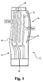
- a core 10 for use in casting a turbine bucket includes a leading edge core section 12 and a trailing edge core section 14.
- the core 10 is divided into the leading edge core section 12 and the trailing edge core section 14 along a split line 16.
- Each section includes one or more serpentine cooling passages 18 as is conventional.
- the trailing edge core section 14 is also shown with a plurality of splitter ribs 20 that serve to separate the flow during cooling.
- the conventional casting die and its supporting structure need not be modified to accommodate the two-piece core of the present invention.
- the leading edge core section 12 and the trailing edge core section 14 can be separately positioned in the casting die so that the wall thickness at the leading edge of the bucket and the trailing edge of the bucket can be independently controlled.
Landscapes
- Engineering & Computer Science (AREA)
- Mechanical Engineering (AREA)
- Molds, Cores, And Manufacturing Methods Thereof (AREA)
- Turbine Rotor Nozzle Sealing (AREA)
- Control Of Turbines (AREA)
Abstract
Description
- The present invention relates to turbine bucket design and, more particularly, to a core design that allows for independent wall thickness control at the airfoil leading edge and trailing edge of a cooled bucket.
- The efficiency of a gas turbine is related to the operating temperature of the turbine and may be increased by increasing the operating temperature. As a practical matter, however, the maximum turbine operating temperature is limited by high temperature capabilities of various turbine elements. Since engine efficiency is limited by temperature considerations, turbine designers have expended considerable effort toward increasing the high temperature capabilities of turbine elements, particularly the airfoil shaped vanes and buckets upon which high temperature combustion products impinge. Various cooling arrangements, systems and methods extend operating temperature limits by keeping airfoils at lower temperatures. The cooling of airfoils is generally accomplished by providing internal flow passages within the airfoils. These serpentine cooling passages accommodate a flow of cooling fluid.
- All portions of the turbine airfoils should be adequately cooled. In particular, adequate cooling should be provided for leading and trailing edges of the airfoils, because these portions are normally the most adversely affected by high temperature combustion gases. Known cooling configurations tend to inadequately cool the airfoils, especially at leading and trailing edges of the airfoils.
- It would be helpful for cooling if the wall thicknesses of the buckets at the leading and trailing edges were optimized. Typically, a one-piece core is supported in a casting die, and prior to the casting procedure, the core is positioned so that the end product wall thicknesses at the leading and trailing edges of the bucket are appropriate to accommodate design considerations. In this context, however, through positioning of the core in the casting die, the optimal positioning of one of the leading edge or the trailing edge for appropriate wall thickness results in sacrificing optimal positioning of the other of the leading or the trailing edge, and the end product may not meet desired part life requirements due to inadequate cooling capabilities.
- In an exemplary embodiment of the invention, a core for use in casting a turbine bucket including serpentine cooling passages includes a leading edge core section positionable in a casting die, and a trailing edge core section separate from the leading edge core section and separately positionable in the casting die. Each of the leading edge core section and the trailing edge core section preferably includes serpentine cooling passages.
- In another exemplary embodiment of the invention, a two-piece core for use in casting a turbine bucket including serpentine cooling passages is provided, wherein each of the pieces is separately positionable in a casting die for independently controlling wall thicknesses at a leading edge and a trailing edge of the turbine bucket.
- In another exemplary embodiment of the invention, a method of casting a turbine bucket includes controlling wall thicknesses at a leading edge and a trailing edge of the turbine bucket independent of each other. In this context, the controlling step preferably includes positioning a leading edge core section in a casting die and separately positioning a trailing edge core section in the casting die.
- The invention will now be described in greater detail, by way of example, with reference to the drawings, in which:-
- FIGURE 1 is a cross sectional view of the two-piece core according to the present invention; and
- FIGURE 2 is a cross sectional view of an end product bucket produced with the two-piece core according to the invention.
-
- Engine buckets are cast in a casting die or mold using a core supported inside the mold. Typically, the core is supported with a six-point nest or the like and is positioned as desired prior to the casting process. The casting process itself does not form part of the present invention, and further details thereof will not be provided. There are several known casting techniques for casting turbine buckets. An exemplary method is disclosed in U.S. Patent No. 5,950,705.
- Referring to FIGURE 1, a
core 10 for use in casting a turbine bucket includes a leadingedge core section 12 and a trailingedge core section 14. Thecore 10 is divided into the leadingedge core section 12 and the trailingedge core section 14 along asplit line 16. Each section includes one or moreserpentine cooling passages 18 as is conventional. The trailingedge core section 14 is also shown with a plurality ofsplitter ribs 20 that serve to separate the flow during cooling. - Because the conventional one-piece core is supported in the casting die via a six-point nest or like set of core locator devices, the conventional casting die and its supporting structure need not be modified to accommodate the two-piece core of the present invention. With this structure, referring to FIGURE 2, the leading
edge core section 12 and the trailingedge core section 14 can be separately positioned in the casting die so that the wall thickness at the leading edge of the bucket and the trailing edge of the bucket can be independently controlled.
Claims (6)
- A core for use in casting a turbine bucket including serpentine cooling passages, the core comprising:a leading edge core section (12) positionable in a casting die; anda trailing edge core section (14) separate from the leading edge core section and separately positionable in the casting die.
- A core according to claim 1, wherein each of the leading edge core section (12) and the trailing edge core section (14) comprises serpentine cooling passages (18).
- A two-piece core for use in casting a turbine bucket including serpentine cooling passages (18), each of the pieces (12,14) being separately positionable in a casting die for independently controlling wall thicknesses at a leading edge and a trailing edge of the turbine bucket.
- A method of casting a turbine bucket comprising controlling wall thicknesses at a leading edge and a trailing edge of the turbine bucket independent of each other.
- A method according to claim 4, wherein the controlling step comprises positioning a leading edge core section (12) in a casting die and separately positioning a trailing edge core section (14) in the casting die.
- A turbine bucket manufactured according to the method of claim 4 or 5.
Applications Claiming Priority (2)
| Application Number | Priority Date | Filing Date | Title |
|---|---|---|---|
| US45590899A | 1999-12-08 | 1999-12-08 | |
| US455908 | 1999-12-08 |
Publications (2)
| Publication Number | Publication Date |
|---|---|
| EP1106280A1 true EP1106280A1 (en) | 2001-06-13 |
| EP1106280B1 EP1106280B1 (en) | 2007-03-07 |
Family
ID=23810721
Family Applications (1)
| Application Number | Title | Priority Date | Filing Date |
|---|---|---|---|
| EP00306599A Expired - Lifetime EP1106280B1 (en) | 1999-12-08 | 2000-08-02 | Core to control turbine bucket wall thickness and method |
Country Status (6)
| Country | Link |
|---|---|
| US (1) | US6464462B2 (en) |
| EP (1) | EP1106280B1 (en) |
| JP (1) | JP2001173404A (en) |
| KR (1) | KR20010067057A (en) |
| AT (1) | ATE355918T1 (en) |
| DE (1) | DE60033768T2 (en) |
Cited By (1)
| Publication number | Priority date | Publication date | Assignee | Title |
|---|---|---|---|---|
| EP1637253A1 (en) * | 2004-09-21 | 2006-03-22 | Snecma | Process of fabricating a turbine blade and core assembly to be used in the process |
Families Citing this family (16)
| Publication number | Priority date | Publication date | Assignee | Title |
|---|---|---|---|---|
| US6860714B1 (en) * | 2002-12-30 | 2005-03-01 | General Electric Company | Gas turbine having alloy castings with craze-free cooling passages |
| US20050000674A1 (en) * | 2003-07-01 | 2005-01-06 | Beddard Thomas Bradley | Perimeter-cooled stage 1 bucket core stabilizing device and related method |
| US6966756B2 (en) * | 2004-01-09 | 2005-11-22 | General Electric Company | Turbine bucket cooling passages and internal core for producing the passages |
| US7690894B1 (en) | 2006-09-25 | 2010-04-06 | Florida Turbine Technologies, Inc. | Ceramic core assembly for serpentine flow circuit in a turbine blade |
| US7762774B2 (en) * | 2006-12-15 | 2010-07-27 | Siemens Energy, Inc. | Cooling arrangement for a tapered turbine blade |
| US7941300B1 (en) * | 2008-02-29 | 2011-05-10 | Florida Turbine Technologies, Inc. | Process for the design of an airfoil |
| US8439628B2 (en) * | 2010-01-06 | 2013-05-14 | General Electric Company | Heat transfer enhancement in internal cavities of turbine engine airfoils |
| KR101006017B1 (en) * | 2010-02-10 | 2011-01-06 | 주식회사 건양기술공사 건축사사무소 | Porch drain of apartment which can reduce drainage noise |
| US20120269649A1 (en) * | 2011-04-22 | 2012-10-25 | Christopher Rawlings | Turbine blade with improved trailing edge cooling |
| US9551226B2 (en) | 2013-10-23 | 2017-01-24 | General Electric Company | Turbine bucket with endwall contour and airfoil profile |
| US9528379B2 (en) | 2013-10-23 | 2016-12-27 | General Electric Company | Turbine bucket having serpentine core |
| US9670784B2 (en) | 2013-10-23 | 2017-06-06 | General Electric Company | Turbine bucket base having serpentine cooling passage with leading edge cooling |
| US9638041B2 (en) | 2013-10-23 | 2017-05-02 | General Electric Company | Turbine bucket having non-axisymmetric base contour |
| US9797258B2 (en) * | 2013-10-23 | 2017-10-24 | General Electric Company | Turbine bucket including cooling passage with turn |
| US9957815B2 (en) | 2015-03-05 | 2018-05-01 | United Technologies Corporation | Gas powered turbine component including serpentine cooling |
| US10107108B2 (en) | 2015-04-29 | 2018-10-23 | General Electric Company | Rotor blade having a flared tip |
Citations (3)
| Publication number | Priority date | Publication date | Assignee | Title |
|---|---|---|---|---|
| EP0130038A1 (en) * | 1983-06-20 | 1985-01-02 | General Electric Company | Turbulence promotion |
| EP0715913A1 (en) * | 1992-02-05 | 1996-06-12 | Howmet Corporation | Multiple part cores for investment casting |
| WO1999059748A1 (en) * | 1998-05-14 | 1999-11-25 | Siemens Aktiengesellschaft | Method and device for producing a metallic hollow body |
Family Cites Families (23)
| Publication number | Priority date | Publication date | Assignee | Title |
|---|---|---|---|---|
| US3844728A (en) | 1968-03-20 | 1974-10-29 | United Aircraft Corp | Gas contacting element leading edge and trailing edge insert |
| US3662816A (en) | 1968-10-01 | 1972-05-16 | Trw Inc | Means for preventing core shift in casting articles |
| US3596703A (en) | 1968-10-01 | 1971-08-03 | Trw Inc | Method of preventing core shift in casting articles |
| US4093017A (en) | 1975-12-29 | 1978-06-06 | Sherwood Refractories, Inc. | Cores for investment casting process |
| US4272953A (en) * | 1978-10-26 | 1981-06-16 | Rice Ivan G | Reheat gas turbine combined with steam turbine |
| US4364160A (en) | 1980-11-03 | 1982-12-21 | General Electric Company | Method of fabricating a hollow article |
| GB2096523B (en) | 1981-03-25 | 1986-04-09 | Rolls Royce | Method of making a blade aerofoil for a gas turbine |
| US4596281A (en) | 1982-09-02 | 1986-06-24 | Trw Inc. | Mold core and method of forming internal passages in an airfoil |
| CH672450A5 (en) | 1987-05-13 | 1989-11-30 | Bbc Brown Boveri & Cie | |
| JPH01244103A (en) * | 1988-03-25 | 1989-09-28 | Hitachi Ltd | Core plug for turbine stationary blade |
| US5050665A (en) | 1989-12-26 | 1991-09-24 | United Technologies Corporation | Investment cast airfoil core/shell lock and method of casting |
| FR2672003B1 (en) | 1991-01-30 | 1993-04-09 | Snecma | PROCESS FOR PRODUCING COMPLEX CERAMIC CORES FOR FOUNDRY. |
| US5296308A (en) | 1992-08-10 | 1994-03-22 | Howmet Corporation | Investment casting using core with integral wall thickness control means |
| US5337805A (en) | 1992-11-24 | 1994-08-16 | United Technologies Corporation | Airfoil core trailing edge region |
| US5351395A (en) | 1992-12-30 | 1994-10-04 | General Electric Company | Process for producing turbine bucket with water droplet erosion protection |
| US5465780A (en) | 1993-11-23 | 1995-11-14 | Alliedsignal Inc. | Laser machining of ceramic cores |
| US5445498A (en) | 1994-06-10 | 1995-08-29 | General Electric Company | Bucket for next-to-the-last stage of a turbine |
| US5509784A (en) | 1994-07-27 | 1996-04-23 | General Electric Co. | Turbine bucket and wheel assembly with integral bucket shroud |
| US5947181A (en) * | 1996-07-10 | 1999-09-07 | General Electric Co. | Composite, internal reinforced ceramic cores and related methods |
| JPH1052736A (en) | 1996-08-09 | 1998-02-24 | Honda Motor Co Ltd | Method for producing hollow casting by lost wax method |
| US5820774A (en) * | 1996-10-28 | 1998-10-13 | United Technologies Corporation | Ceramic core for casting a turbine blade |
| US5950705A (en) * | 1996-12-03 | 1999-09-14 | General Electric Company | Method for casting and controlling wall thickness |
| US6347660B1 (en) * | 1998-12-01 | 2002-02-19 | Howmet Research Corporation | Multipiece core assembly for cast airfoil |
-
2000
- 2000-08-02 EP EP00306599A patent/EP1106280B1/en not_active Expired - Lifetime
- 2000-08-02 DE DE60033768T patent/DE60033768T2/en not_active Expired - Lifetime
- 2000-08-02 AT AT00306599T patent/ATE355918T1/en not_active IP Right Cessation
- 2000-08-04 JP JP2000236313A patent/JP2001173404A/en active Pending
- 2000-08-04 KR KR1020000045172A patent/KR20010067057A/en not_active Ceased
-
2001
- 2001-08-08 US US09/923,915 patent/US6464462B2/en not_active Expired - Lifetime
Patent Citations (3)
| Publication number | Priority date | Publication date | Assignee | Title |
|---|---|---|---|---|
| EP0130038A1 (en) * | 1983-06-20 | 1985-01-02 | General Electric Company | Turbulence promotion |
| EP0715913A1 (en) * | 1992-02-05 | 1996-06-12 | Howmet Corporation | Multiple part cores for investment casting |
| WO1999059748A1 (en) * | 1998-05-14 | 1999-11-25 | Siemens Aktiengesellschaft | Method and device for producing a metallic hollow body |
Cited By (4)
| Publication number | Priority date | Publication date | Assignee | Title |
|---|---|---|---|---|
| EP1637253A1 (en) * | 2004-09-21 | 2006-03-22 | Snecma | Process of fabricating a turbine blade and core assembly to be used in the process |
| FR2875425A1 (en) * | 2004-09-21 | 2006-03-24 | Snecma Moteurs Sa | PROCESS FOR MANUFACTURING A TURBOMACHINE BLADE, CORE ASSEMBLY FOR CARRYING OUT THE PROCESS |
| US7246653B2 (en) | 2004-09-21 | 2007-07-24 | Snecma | Process for manufacturing the blade of turbomachine, and assembly of the cores for implementation of the process |
| US7556083B2 (en) | 2004-09-21 | 2009-07-07 | Snecma | Process for manufacturing the blade of a turbomachine, and assembly of the cores for implementation of the process |
Also Published As
| Publication number | Publication date |
|---|---|
| ATE355918T1 (en) | 2007-03-15 |
| KR20010067057A (en) | 2001-07-12 |
| JP2001173404A (en) | 2001-06-26 |
| EP1106280B1 (en) | 2007-03-07 |
| US20020012590A1 (en) | 2002-01-31 |
| US6464462B2 (en) | 2002-10-15 |
| DE60033768D1 (en) | 2007-04-19 |
| DE60033768T2 (en) | 2007-11-08 |
Similar Documents
| Publication | Publication Date | Title |
|---|---|---|
| EP1106280A1 (en) | Core to control turbine bucket wall thickness and method | |
| JP4731238B2 (en) | Apparatus for cooling a gas turbine engine rotor blade | |
| JP4948797B2 (en) | Method and apparatus for cooling a gas turbine engine rotor blade | |
| EP1079072B1 (en) | Blade tip cooling | |
| EP1762701B1 (en) | Skewed tip hole turbine blade | |
| EP2855857B1 (en) | Blade outer air seal with cored passages | |
| EP1088964A2 (en) | Slotted impingement cooling of airfoil leading edge | |
| US20160097286A1 (en) | Internal cooling of engine components | |
| US6382908B1 (en) | Nozzle fillet backside cooling | |
| JP4731237B2 (en) | Apparatus for cooling a gas turbine engine rotor blade | |
| EP1068428A1 (en) | Apparatus for cooling a gas turbine airfoil and method of making same | |
| JP2005299637A (en) | Method and apparatus for reducing turbine blade temperature | |
| JP2002276302A (en) | Method, airfoil, and turbine engine for reducing temperature in turbine blade tip region | |
| JP2003120206A (en) | Method and apparatus for extending the useful life of a gas turbine engine airfoil | |
| JP2003214108A (en) | Moving blade for high pressure turbine provided with rear edge having improved temperature characteristic | |
| JP2005351277A (en) | Method and apparatus for cooling gas turbine rotor blades | |
| US20050111963A1 (en) | Turbine blade/vane and casting system for manufacturing a turbine blade/vane | |
| JP2003193804A (en) | Improvement of high temperature state of rear edge of high pressure turbine blade | |
| US6824352B1 (en) | Vane enhanced trailing edge cooling design | |
| JP2007218256A (en) | Turbine airfoil with reduced plenum | |
| US6957948B2 (en) | Turbine blade attachment lightening holes | |
| EP3581294B1 (en) | Casting plug with flow control features | |
| CZ20002890A3 (en) | Turbine vane casting core |
Legal Events
| Date | Code | Title | Description |
|---|---|---|---|
| PUAI | Public reference made under article 153(3) epc to a published international application that has entered the european phase |
Free format text: ORIGINAL CODE: 0009012 |
|
| AK | Designated contracting states |
Kind code of ref document: A1 Designated state(s): AT BE CH CY DE DK ES FI FR GB GR IE IT LI LU MC NL PT SE |
|
| AX | Request for extension of the european patent |
Free format text: AL;LT;LV;MK;RO;SI |
|
| 17P | Request for examination filed |
Effective date: 20011213 |
|
| AKX | Designation fees paid |
Free format text: AT BE CH CY DE DK ES FI FR GB GR IE IT LI LU MC NL PT SE |
|
| 17Q | First examination report despatched |
Effective date: 20040225 |
|
| GRAP | Despatch of communication of intention to grant a patent |
Free format text: ORIGINAL CODE: EPIDOSNIGR1 |
|
| GRAS | Grant fee paid |
Free format text: ORIGINAL CODE: EPIDOSNIGR3 |
|
| GRAA | (expected) grant |
Free format text: ORIGINAL CODE: 0009210 |
|
| AK | Designated contracting states |
Kind code of ref document: B1 Designated state(s): AT BE CH CY DE DK ES FI FR GB GR IE IT LI LU MC NL PT SE |
|
| PG25 | Lapsed in a contracting state [announced via postgrant information from national office to epo] |
Ref country code: BE Free format text: LAPSE BECAUSE OF FAILURE TO SUBMIT A TRANSLATION OF THE DESCRIPTION OR TO PAY THE FEE WITHIN THE PRESCRIBED TIME-LIMIT Effective date: 20070307 Ref country code: AT Free format text: LAPSE BECAUSE OF FAILURE TO SUBMIT A TRANSLATION OF THE DESCRIPTION OR TO PAY THE FEE WITHIN THE PRESCRIBED TIME-LIMIT Effective date: 20070307 Ref country code: FI Free format text: LAPSE BECAUSE OF FAILURE TO SUBMIT A TRANSLATION OF THE DESCRIPTION OR TO PAY THE FEE WITHIN THE PRESCRIBED TIME-LIMIT Effective date: 20070307 |
|
| REG | Reference to a national code |
Ref country code: GB Ref legal event code: FG4D |
|
| REG | Reference to a national code |
Ref country code: CH Ref legal event code: EP |
|
| REG | Reference to a national code |
Ref country code: CH Ref legal event code: NV Representative=s name: SERVOPATENT GMBH |
|
| REF | Corresponds to: |
Ref document number: 60033768 Country of ref document: DE Date of ref document: 20070419 Kind code of ref document: P |
|
| REG | Reference to a national code |
Ref country code: IE Ref legal event code: FG4D |
|
| PG25 | Lapsed in a contracting state [announced via postgrant information from national office to epo] |
Ref country code: ES Free format text: LAPSE BECAUSE OF FAILURE TO SUBMIT A TRANSLATION OF THE DESCRIPTION OR TO PAY THE FEE WITHIN THE PRESCRIBED TIME-LIMIT Effective date: 20070618 |
|
| REG | Reference to a national code |
Ref country code: SE Ref legal event code: TRGR |
|
| ET | Fr: translation filed | ||
| PG25 | Lapsed in a contracting state [announced via postgrant information from national office to epo] |
Ref country code: PT Free format text: LAPSE BECAUSE OF FAILURE TO SUBMIT A TRANSLATION OF THE DESCRIPTION OR TO PAY THE FEE WITHIN THE PRESCRIBED TIME-LIMIT Effective date: 20070807 |
|
| PLBE | No opposition filed within time limit |
Free format text: ORIGINAL CODE: 0009261 |
|
| STAA | Information on the status of an ep patent application or granted ep patent |
Free format text: STATUS: NO OPPOSITION FILED WITHIN TIME LIMIT |
|
| PG25 | Lapsed in a contracting state [announced via postgrant information from national office to epo] |
Ref country code: DK Free format text: LAPSE BECAUSE OF FAILURE TO SUBMIT A TRANSLATION OF THE DESCRIPTION OR TO PAY THE FEE WITHIN THE PRESCRIBED TIME-LIMIT Effective date: 20070307 |
|
| 26N | No opposition filed |
Effective date: 20071210 |
|
| REG | Reference to a national code |
Ref country code: CH Ref legal event code: PFA Owner name: GENERAL ELECTRIC COMPANY Free format text: GENERAL ELECTRIC COMPANY#1 RIVER ROAD#SCHENECTADY, NY 12345 (US) -TRANSFER TO- GENERAL ELECTRIC COMPANY#1 RIVER ROAD#SCHENECTADY, NY 12345 (US) |
|
| PG25 | Lapsed in a contracting state [announced via postgrant information from national office to epo] |
Ref country code: MC Free format text: LAPSE BECAUSE OF NON-PAYMENT OF DUE FEES Effective date: 20070831 Ref country code: GR Free format text: LAPSE BECAUSE OF FAILURE TO SUBMIT A TRANSLATION OF THE DESCRIPTION OR TO PAY THE FEE WITHIN THE PRESCRIBED TIME-LIMIT Effective date: 20070608 |
|
| PG25 | Lapsed in a contracting state [announced via postgrant information from national office to epo] |
Ref country code: IE Free format text: LAPSE BECAUSE OF NON-PAYMENT OF DUE FEES Effective date: 20070802 |
|
| PG25 | Lapsed in a contracting state [announced via postgrant information from national office to epo] |
Ref country code: CY Free format text: LAPSE BECAUSE OF FAILURE TO SUBMIT A TRANSLATION OF THE DESCRIPTION OR TO PAY THE FEE WITHIN THE PRESCRIBED TIME-LIMIT Effective date: 20070307 |
|
| PG25 | Lapsed in a contracting state [announced via postgrant information from national office to epo] |
Ref country code: LU Free format text: LAPSE BECAUSE OF NON-PAYMENT OF DUE FEES Effective date: 20070802 |
|
| PGFP | Annual fee paid to national office [announced via postgrant information from national office to epo] |
Ref country code: NL Payment date: 20130826 Year of fee payment: 14 Ref country code: SE Payment date: 20130828 Year of fee payment: 14 |
|
| REG | Reference to a national code |
Ref country code: NL Ref legal event code: V1 Effective date: 20150301 |
|
| REG | Reference to a national code |
Ref country code: SE Ref legal event code: EUG |
|
| PG25 | Lapsed in a contracting state [announced via postgrant information from national office to epo] |
Ref country code: NL Free format text: LAPSE BECAUSE OF NON-PAYMENT OF DUE FEES Effective date: 20150301 |
|
| PG25 | Lapsed in a contracting state [announced via postgrant information from national office to epo] |
Ref country code: SE Free format text: LAPSE BECAUSE OF NON-PAYMENT OF DUE FEES Effective date: 20140803 |
|
| REG | Reference to a national code |
Ref country code: FR Ref legal event code: PLFP Year of fee payment: 17 |
|
| REG | Reference to a national code |
Ref country code: FR Ref legal event code: PLFP Year of fee payment: 18 |
|
| REG | Reference to a national code |
Ref country code: FR Ref legal event code: PLFP Year of fee payment: 19 |
|
| PGFP | Annual fee paid to national office [announced via postgrant information from national office to epo] |
Ref country code: FR Payment date: 20190722 Year of fee payment: 20 Ref country code: IT Payment date: 20190722 Year of fee payment: 20 Ref country code: DE Payment date: 20190722 Year of fee payment: 20 |
|
| PGFP | Annual fee paid to national office [announced via postgrant information from national office to epo] |
Ref country code: GB Payment date: 20190722 Year of fee payment: 20 |
|
| PGFP | Annual fee paid to national office [announced via postgrant information from national office to epo] |
Ref country code: CH Payment date: 20190722 Year of fee payment: 20 |
|
| REG | Reference to a national code |
Ref country code: CH Ref legal event code: PCAR Free format text: NEW ADDRESS: WANNERSTRASSE 9/1, 8045 ZUERICH (CH) |
|
| REG | Reference to a national code |
Ref country code: DE Ref legal event code: R071 Ref document number: 60033768 Country of ref document: DE |
|
| REG | Reference to a national code |
Ref country code: CH Ref legal event code: PL |
|
| REG | Reference to a national code |
Ref country code: GB Ref legal event code: PE20 Expiry date: 20200801 |
|
| PG25 | Lapsed in a contracting state [announced via postgrant information from national office to epo] |
Ref country code: GB Free format text: LAPSE BECAUSE OF EXPIRATION OF PROTECTION Effective date: 20200801 |