EP1106134A1 - Crockery basket for dishwashers - Google Patents
Crockery basket for dishwashers Download PDFInfo
- Publication number
- EP1106134A1 EP1106134A1 EP00123839A EP00123839A EP1106134A1 EP 1106134 A1 EP1106134 A1 EP 1106134A1 EP 00123839 A EP00123839 A EP 00123839A EP 00123839 A EP00123839 A EP 00123839A EP 1106134 A1 EP1106134 A1 EP 1106134A1
- Authority
- EP
- European Patent Office
- Prior art keywords
- bearing
- crockery basket
- base
- bearing shaft
- basket
- Prior art date
- Legal status (The legal status is an assumption and is not a legal conclusion. Google has not performed a legal analysis and makes no representation as to the accuracy of the status listed.)
- Granted
Links
- 239000002184 metal Substances 0.000 claims abstract description 4
- 230000002093 peripheral effect Effects 0.000 claims description 2
- 238000004851 dishwashing Methods 0.000 abstract 1
- 238000000034 method Methods 0.000 description 1
Images
Classifications
-
- A—HUMAN NECESSITIES
- A47—FURNITURE; DOMESTIC ARTICLES OR APPLIANCES; COFFEE MILLS; SPICE MILLS; SUCTION CLEANERS IN GENERAL
- A47L—DOMESTIC WASHING OR CLEANING; SUCTION CLEANERS IN GENERAL
- A47L15/00—Washing or rinsing machines for crockery or tableware
- A47L15/42—Details
- A47L15/50—Racks ; Baskets
- A47L15/503—Racks ; Baskets with foldable parts
Definitions
- the invention concerns a crockery basket for dishwashers, which is formed from metal rods and which has a base, sides and tilting racks which are fitted with a row of spars, wherein the spars of each rack are attached to a bearing shaft, which can be rotated within bearing mounts of the crockery basket facing downwards and wherein when the spars are in the vertical position, the racks can be engaged onto the basket frame or moved into a folded position onto the base of the crockery basket.
- the task of the invention is to create a crockery basket of the design described above, with a view to improving and simplifying the arrangement of the rack and handling of same.
- each rack with the bearing shaft is engaged onto at least two bearing mounts by bearing struts of the crockery basket which are positioned transverse to the bearing shaft and with the bearing shaft supported on base rods positioned transverse to the bearing shaft, in that at least one spar has a latch end with latch mount extending beyond the bearing shaft, which are engaged in the vertical position of the spar by a base rod of the crockery basket positioned parallel to the bearing shaft and in that once the latch connection between the base rod and the latch end is disengaged, the rack can be folded down onto the base of the crockery basket.
- the arrangement is constructed such that the latch end of the spar is formed in the shape of a C and when the spars are upright, the latch mounts open facing upwards.
- the bearing struts extend over a part of the dimension of the crockery basket transverse to the bearing shaft of the rack and have bearing mounts at both ends
- the bearing struts can be used for the rotating position of two connected racks for plates or similar.
- the only difference between the two racks lies in the method of securing and aligning the spar with the latch end.
- the cost of the basket components is kept low in that the base rods running parallel to the shaft ends of the rack, with the ends vertical, form wall rods angled upwards, to which peripheral, horizontal wall rods are attached.
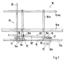
- Fig.1 shows a crockery basket 10 formed from metal rods and its base rods 101 and 10q arranged in the base area, which are aligned in the longitudinal and transverse direction of the crockery basket 10.
- the longitudinal base rods 101 are attached to the transverse base rods 10q.
- the longitudinal base rods 101 are angled upwards at right angles on the ends 10le and serve as vertical wall rods, to which horizontally running wall rods 10w and 10wa are attached, thereby completing the physical carcass of the crockery basket 10.
- the racks 25 with the row of spars 20 have at one end of the spars 20 a bearing shaft 21, on which the crockery basket 10 can be rotated.
- a bearing shaft 21 attached to the underside of longitudinal base rods 101, are at least two separate bearing struts 15, the ends 15e of which are fitted with latch mounts 16 facing downwards.
- the bearing shafts 21 of the racks 25 are mounted and engaged onto these latch mounts 16 together with the transverse base rods 10q, wherein the bearing shafts 21 are supported by the transverse base rods 10q.
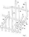
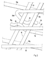
- FIGs. 2 and 3 illustrate in more detail the two positions of the rack 25 on the crockery basket 10. At least one spar 20 of a rack 25 extends beyond the bearing shaft 21 and forms a C-shaped end 20e with latch 22 for a longitudinal base rod 101.
- the latch mount 22 faces upwards and faces onto a longitudinal base rod 101 adjacent to the rotating bearing arrangement, as shown clearly by Figs. 1 and 2. If the rack 25 is subjected to a rotational movement, this locking connection between the end 20e of the spar 20 and the longitudinal base rod 101 is released and the rods can be folded down onto the longitudinal base rods 101, as shown by the 20' position shown in Figs.1 and 3.
- two racks 25 can be rotated on the bearing struts 15.
- the racks 25 are formed as mirror images and can be folded against each other, as shown by Fig.1. Thus, the required positions engage onto the longitudinal base rods 101 arranged between the bearing shafts 21.
- the two racks 25 rotate in opposite directions.
Landscapes
- Washing And Drying Of Tableware (AREA)
- Details Of Rigid Or Semi-Rigid Containers (AREA)
Abstract
Description
- The invention concerns a crockery basket for dishwashers, which is formed from metal rods and which has a base, sides and tilting racks which are fitted with a row of spars, wherein the spars of each rack are attached to a bearing shaft, which can be rotated within bearing mounts of the crockery basket facing downwards and wherein when the spars are in the vertical position, the racks can be engaged onto the basket frame or moved into a folded position onto the base of the crockery basket.
- A crockery basket of this design is known from EP 0 797 949 A 2. In this case, fitted to the ends of the bearing shaft of a rack are C-shaped catches, which are aligned towards each other and guided into double lugs specially fitted to the sides of the crockery basket, so that when pushed and rotated, they can be moved into two positions, in which the spars of the frame are either in an upright vertical position, or folded down onto the base of the crockery basket. This results in an arrangement with a large bearing clearance, which causes an insecure fixing of the rack in the required position. Moreover, the structural design of the crockery basket with the additional double lugs is expensive and handling of the rack is unwieldy due to the adjustment in two directions.
- A similar design of crockery basket equipped with folding racks is disclosed in DE 197 55 339 A1. However, alternatively shaped bearing shafts and special guide components for the bearing shafts are used on the sides of the crockery basket. The design of the crockery basket and the handling of the rack are therefore encumbered by the same disadvantages.
- The task of the invention is to create a crockery basket of the design described above, with a view to improving and simplifying the arrangement of the rack and handling of same.
- The task is solved in accordance with the invention in that each rack with the bearing shaft is engaged onto at least two bearing mounts by bearing struts of the crockery basket which are positioned transverse to the bearing shaft and with the bearing shaft supported on base rods positioned transverse to the bearing shaft, in that at least one spar has a latch end with latch mount extending beyond the bearing shaft, which are engaged in the vertical position of the spar by a base rod of the crockery basket positioned parallel to the bearing shaft and in that once the latch connection between the base rod and the latch end is disengaged, the rack can be folded down onto the base of the crockery basket.
- Through the latch connection between the bearing shaft of a rack and the bearing struts of the crockery basket, in connection with the support of the bearing shaft on the base rods of the crockery basket, an almost zero-play rotating position is achieved for the rack, which can also easily be released. By fitting a latch end to at least one spar on the rack and by engaging this spar onto a base rod running parallel to the bearing shaft, it is simple to engage the rack into the position for use, wherein the only action required is a simple rotational movement onto the rack.
- To engage the rack, the arrangement is constructed such that the latch end of the spar is formed in the shape of a C and when the spars are upright, the latch mounts open facing upwards.
- If according to a further design, the bearing struts extend over a part of the dimension of the crockery basket transverse to the bearing shaft of the rack and have bearing mounts at both ends, the bearing struts can be used for the rotating position of two connected racks for plates or similar. In this case, it is preferential for the two racks located on the bearing struts to fold towards each other onto the base of the crockery basket, wherein if the spars are in the vertical position, the latch ends of the rack are facing each other and wherein the latch ends are engaged onto the base rods that run parallel between the bearing shafts. The only difference between the two racks lies in the method of securing and aligning the spar with the latch end.
- The cost of the basket components is kept low in that the base rods running parallel to the shaft ends of the rack, with the ends vertical, form wall rods angled upwards, to which peripheral, horizontal wall rods are attached.
- The invention is explained in more detail by way of one of the design examples illustrated in the drawings. The following are shown:
- Fig. 1
- a partial view of the crockery basket showing details of the rotating position and locking of the racks with a row of spars,
- Fig. 2
- an exploded partial view with a rack locked into the position for use with spars in the vertical position, and
- Fig. 3
- an exploded partial view with rack folded onto the base of the basket.
- Fig.1 shows a
crockery basket 10 formed from metal rods and itsbase rods crockery basket 10. Thus, thelongitudinal base rods 101 are attached to thetransverse base rods 10q. Thelongitudinal base rods 101 are angled upwards at right angles on the ends 10le and serve as vertical wall rods, to which horizontally runningwall rods 10w and 10wa are attached, thereby completing the physical carcass of thecrockery basket 10. - The
racks 25 with the row ofspars 20 have at one end of the spars 20 abearing shaft 21, on which thecrockery basket 10 can be rotated. Thus, attached to the underside oflongitudinal base rods 101, are at least twoseparate bearing struts 15, theends 15e of which are fitted withlatch mounts 16 facing downwards. Thebearing shafts 21 of theracks 25 are mounted and engaged onto theselatch mounts 16 together with thetransverse base rods 10q, wherein thebearing shafts 21 are supported by thetransverse base rods 10q. - The rotating position thus created operates at practically zero-play, whilst still being simple to disengage.
- The partial views shown in Figs. 2 and 3 illustrate in more detail the two positions of the
rack 25 on thecrockery basket 10. At least onespar 20 of arack 25 extends beyond thebearing shaft 21 and forms a C-shaped end 20e withlatch 22 for alongitudinal base rod 101. - In the required position with the
spars 20 in the vertical position, the latch mount 22 faces upwards and faces onto alongitudinal base rod 101 adjacent to the rotating bearing arrangement, as shown clearly by Figs. 1 and 2. If therack 25 is subjected to a rotational movement, this locking connection between theend 20e of thespar 20 and thelongitudinal base rod 101 is released and the rods can be folded down onto thelongitudinal base rods 101, as shown by the 20' position shown in Figs.1 and 3. - If the
bearing struts 15 with theirends 15e project beyond twolongitudinal base rods 101, tworacks 25 can be rotated on thebearing struts 15. Theracks 25 are formed as mirror images and can be folded against each other, as shown by Fig.1. Thus, the required positions engage onto thelongitudinal base rods 101 arranged between thebearing shafts 21. The two racks 25 rotate in opposite directions.
Claims (5)
- A crockery basket for dishwashers, which is formed from metal rods and which has a base, sides and tilting racks which are fitted with a row of spars, wherein the spars of each rack are attached to a bearing shaft, which can be rotated within bearing mounts of the crockery basket facing downwards and wherein when the spars are in the vertical position, the racks can be engaged onto the basket frame or moved into a folded position onto the base of the crockery basket,
characterised in that
each rack (25) with the bearing shaft (21) is engaged onto at least two bearing mounts (16) by bearing struts (15) of the crockery basket (10) which are positioned transverse to the bearing shaft (21) and with the bearing shaft (21) supported on base rods (10q) positioned transverse to the bearing shaft (21), at least one spar (20) has a latch end (20e) with latch mount (22) extending beyond the bearing shaft (21), which are engaged in the vertical position of the spar (20) by a base rod (101) of the crockery basket (10) positioned parallel to the bearing shaft (21),
and
in that once the latch connection between base rod (101) and latch end (20e) is disengaged, the rack (25) can be folded down onto the base of crockery basket (10). - Crockery basket in accordance with Claim 1,
characterised in that
the latch end (20e) of the spar (20) is formed in a C-shape and in the vertical spar (20) position has a lock mount (22) facing upwards. - Crockery basket in accordance with Claim 1 or 2,
characterised in that
the bearing struts (15) extend over a part of the dimension of the crockery basket (10) transverse to the bearing shafts (21) of the rack (25) and have bearing mounts (16) at both ends (15e). - Crockery basket in accordance with Claim 3,
characterised in that
the two racks (25, 25') located on the bearing struts (15) can be folded towards each other onto the base of the crockery basket (10), wherein if the spars (20) are in the vertical position, the latch ends (20e) of the racks (25,25') are positioned opposite each other and wherein the latch ends (20e) are engaged onto the base rods (101) that run parallel between the bearing shafts (21). - Crockery basket in accordance with Claims 1 to 4,
characterised in that
the base rods (10|) running parallel to the bearing shafts (21) of the racks (25) with the ends (10|e) form wall rods angled upwards, to which peripheral, horizontal wall rods (10w, 10wa) are attached.
Applications Claiming Priority (2)
| Application Number | Priority Date | Filing Date | Title |
|---|---|---|---|
| DE29921601U DE29921601U1 (en) | 1999-12-08 | 1999-12-08 | Dish rack for dishwashers |
| DE29921601U | 1999-12-08 |
Publications (2)
| Publication Number | Publication Date |
|---|---|
| EP1106134A1 true EP1106134A1 (en) | 2001-06-13 |
| EP1106134B1 EP1106134B1 (en) | 2007-07-04 |
Family
ID=8082689
Family Applications (1)
| Application Number | Title | Priority Date | Filing Date |
|---|---|---|---|
| EP20000123839 Expired - Lifetime EP1106134B1 (en) | 1999-12-08 | 2000-11-02 | Crockery basket for dishwashers |
Country Status (3)
| Country | Link |
|---|---|
| EP (1) | EP1106134B1 (en) |
| DE (2) | DE29921601U1 (en) |
| ES (1) | ES2285987T3 (en) |
Cited By (2)
| Publication number | Priority date | Publication date | Assignee | Title |
|---|---|---|---|---|
| EP1336370A3 (en) * | 2002-02-06 | 2005-01-12 | Electrolux Home Products Corporation N.V. | Foldable dish holder rack placed in a dishwashing machine basket |
| US8356719B2 (en) * | 2008-03-26 | 2013-01-22 | Bsh Bosch Und Siemens Hausgeraete Gmbh | Crockery basket and dishwasher |
Families Citing this family (6)
| Publication number | Priority date | Publication date | Assignee | Title |
|---|---|---|---|---|
| ES2250387T3 (en) * | 2000-04-20 | 2006-04-16 | Arcelik A.S. | FOLDING PORTAVASES GRIDS. |
| EP1286616B1 (en) * | 2000-05-12 | 2007-10-31 | Arcelik A.S. | Dishwasher basket with foldable crockery holder racks |
| DE10332149B3 (en) * | 2003-07-15 | 2005-05-04 | Miele & Cie. Kg | A crockery basket for dishwasher, has an adjustable holder for cups and the like which may be tilted into position and held by a wire formed construction |
| DE102008015716A1 (en) | 2008-03-26 | 2010-07-01 | BSH Bosch und Siemens Hausgeräte GmbH | Dish rack and dishwasher |
| DE102008015715A1 (en) | 2008-03-26 | 2009-10-01 | BSH Bosch und Siemens Hausgeräte GmbH | Dish rack and dishwasher |
| DE102008015714A1 (en) | 2008-03-26 | 2009-10-01 | BSH Bosch und Siemens Hausgeräte GmbH | Dish rack and dishwasher |
Citations (4)
| Publication number | Priority date | Publication date | Assignee | Title |
|---|---|---|---|---|
| DE3417744A1 (en) * | 1984-05-12 | 1985-11-21 | Miele & Cie GmbH & Co, 4830 Gütersloh | Crockery basket, in particular upper basket for a dish-washing machine |
| US4606464A (en) * | 1985-01-17 | 1986-08-19 | The Maytag Company | Dishwasher rack with pivoted divider assembly |
| EP0797949A2 (en) * | 1996-03-27 | 1997-10-01 | SMEG S.p.A. | Dishwasher basket with foldable plate-holding racks |
| DE29722001U1 (en) * | 1996-12-13 | 1998-02-12 | Merloni Elettrodomestici S.P.A., Fabriano, Ancona | Dishwasher basket |
-
1999
- 1999-12-08 DE DE29921601U patent/DE29921601U1/en not_active Expired - Lifetime
-
2000
- 2000-11-02 DE DE2000635400 patent/DE60035400T2/en not_active Expired - Lifetime
- 2000-11-02 EP EP20000123839 patent/EP1106134B1/en not_active Expired - Lifetime
- 2000-11-02 ES ES00123839T patent/ES2285987T3/en not_active Expired - Lifetime
Patent Citations (4)
| Publication number | Priority date | Publication date | Assignee | Title |
|---|---|---|---|---|
| DE3417744A1 (en) * | 1984-05-12 | 1985-11-21 | Miele & Cie GmbH & Co, 4830 Gütersloh | Crockery basket, in particular upper basket for a dish-washing machine |
| US4606464A (en) * | 1985-01-17 | 1986-08-19 | The Maytag Company | Dishwasher rack with pivoted divider assembly |
| EP0797949A2 (en) * | 1996-03-27 | 1997-10-01 | SMEG S.p.A. | Dishwasher basket with foldable plate-holding racks |
| DE29722001U1 (en) * | 1996-12-13 | 1998-02-12 | Merloni Elettrodomestici S.P.A., Fabriano, Ancona | Dishwasher basket |
Cited By (2)
| Publication number | Priority date | Publication date | Assignee | Title |
|---|---|---|---|---|
| EP1336370A3 (en) * | 2002-02-06 | 2005-01-12 | Electrolux Home Products Corporation N.V. | Foldable dish holder rack placed in a dishwashing machine basket |
| US8356719B2 (en) * | 2008-03-26 | 2013-01-22 | Bsh Bosch Und Siemens Hausgeraete Gmbh | Crockery basket and dishwasher |
Also Published As
| Publication number | Publication date |
|---|---|
| DE60035400D1 (en) | 2007-08-16 |
| ES2285987T3 (en) | 2007-12-01 |
| DE60035400T2 (en) | 2007-10-31 |
| EP1106134B1 (en) | 2007-07-04 |
| DE29921601U1 (en) | 2000-02-17 |
Similar Documents
| Publication | Publication Date | Title |
|---|---|---|
| US7458599B2 (en) | Luggage basket and folding baby carriage provided with the same | |
| US5941228A (en) | Release and lock system for the fold down barbeque shelves | |
| US20120204407A1 (en) | System and Method for Mounting Different Types of Infant Carriers on a Support Structure | |
| EP1106134B1 (en) | Crockery basket for dishwashers | |
| EP0797949B1 (en) | Dishwasher basket with foldable plate-holding racks | |
| KR20100031189A (en) | The foldable cart | |
| GB2321394A (en) | Basket for a dishwashing machine | |
| CN117365195A (en) | Self-healing door lock | |
| EP0711527B1 (en) | Dishwasher with U-shaped support frame | |
| CN118902352B (en) | A dish rack | |
| KR200448204Y1 (en) | Rotating cabinet | |
| GB2190895A (en) | Interengageable pallets | |
| EP1001071A1 (en) | Clothes drying rack | |
| US3575440A (en) | Serving cart | |
| WO2011115263A1 (en) | Medicine cart | |
| JP2007130362A (en) | Article display apparatus | |
| CN223355764U (en) | Front object carrying bracket of electric motorcycle | |
| KR102128351B1 (en) | Shelf for Dishes | |
| CN218055221U (en) | Shopping cart with telescopic crawling ladder | |
| JPH1156480A (en) | Foldable table | |
| CN214631192U (en) | Folding structure of folding bed | |
| KR102500244B1 (en) | A harrow for tractor | |
| CN217592811U (en) | Bowl basket and dish washing machine | |
| CN221430849U (en) | Steaming cabinet carrier | |
| CN223929852U (en) | crib |
Legal Events
| Date | Code | Title | Description |
|---|---|---|---|
| PUAI | Public reference made under article 153(3) epc to a published international application that has entered the european phase |
Free format text: ORIGINAL CODE: 0009012 |
|
| AK | Designated contracting states |
Kind code of ref document: A1 Designated state(s): DE ES FR GB IT SE |
|
| AX | Request for extension of the european patent |
Free format text: AL;LT;LV;MK;RO;SI |
|
| 17P | Request for examination filed |
Effective date: 20011203 |
|
| AKX | Designation fees paid |
Free format text: DE ES FR GB IT SE |
|
| GRAP | Despatch of communication of intention to grant a patent |
Free format text: ORIGINAL CODE: EPIDOSNIGR1 |
|
| GRAS | Grant fee paid |
Free format text: ORIGINAL CODE: EPIDOSNIGR3 |
|
| GRAA | (expected) grant |
Free format text: ORIGINAL CODE: 0009210 |
|
| AK | Designated contracting states |
Kind code of ref document: B1 Designated state(s): DE ES FR GB IT SE |
|
| REG | Reference to a national code |
Ref country code: GB Ref legal event code: FG4D |
|
| REF | Corresponds to: |
Ref document number: 60035400 Country of ref document: DE Date of ref document: 20070816 Kind code of ref document: P |
|
| REG | Reference to a national code |
Ref country code: SE Ref legal event code: TRGR |
|
| ET | Fr: translation filed | ||
| REG | Reference to a national code |
Ref country code: ES Ref legal event code: FG2A Ref document number: 2285987 Country of ref document: ES Kind code of ref document: T3 |
|
| PLBE | No opposition filed within time limit |
Free format text: ORIGINAL CODE: 0009261 |
|
| STAA | Information on the status of an ep patent application or granted ep patent |
Free format text: STATUS: NO OPPOSITION FILED WITHIN TIME LIMIT |
|
| 26N | No opposition filed |
Effective date: 20080407 |
|
| REG | Reference to a national code |
Ref country code: FR Ref legal event code: PLFP Year of fee payment: 16 |
|
| REG | Reference to a national code |
Ref country code: FR Ref legal event code: PLFP Year of fee payment: 17 |
|
| PGFP | Annual fee paid to national office [announced via postgrant information from national office to epo] |
Ref country code: GB Payment date: 20161102 Year of fee payment: 17 Ref country code: DE Payment date: 20161025 Year of fee payment: 17 Ref country code: FR Payment date: 20161014 Year of fee payment: 17 |
|
| PGFP | Annual fee paid to national office [announced via postgrant information from national office to epo] |
Ref country code: SE Payment date: 20161111 Year of fee payment: 17 Ref country code: ES Payment date: 20161011 Year of fee payment: 17 Ref country code: IT Payment date: 20161122 Year of fee payment: 17 |
|
| REG | Reference to a national code |
Ref country code: DE Ref legal event code: R119 Ref document number: 60035400 Country of ref document: DE |
|
| REG | Reference to a national code |
Ref country code: SE Ref legal event code: EUG |
|
| GBPC | Gb: european patent ceased through non-payment of renewal fee |
Effective date: 20171102 |
|
| PG25 | Lapsed in a contracting state [announced via postgrant information from national office to epo] |
Ref country code: SE Free format text: LAPSE BECAUSE OF NON-PAYMENT OF DUE FEES Effective date: 20171103 |
|
| REG | Reference to a national code |
Ref country code: FR Ref legal event code: ST Effective date: 20180731 |
|
| PG25 | Lapsed in a contracting state [announced via postgrant information from national office to epo] |
Ref country code: DE Free format text: LAPSE BECAUSE OF NON-PAYMENT OF DUE FEES Effective date: 20180602 Ref country code: FR Free format text: LAPSE BECAUSE OF NON-PAYMENT OF DUE FEES Effective date: 20171130 Ref country code: IT Free format text: LAPSE BECAUSE OF NON-PAYMENT OF DUE FEES Effective date: 20171102 |
|
| PG25 | Lapsed in a contracting state [announced via postgrant information from national office to epo] |
Ref country code: GB Free format text: LAPSE BECAUSE OF NON-PAYMENT OF DUE FEES Effective date: 20171102 |
|
| REG | Reference to a national code |
Ref country code: ES Ref legal event code: FD2A Effective date: 20181226 |
|
| PG25 | Lapsed in a contracting state [announced via postgrant information from national office to epo] |
Ref country code: ES Free format text: LAPSE BECAUSE OF NON-PAYMENT OF DUE FEES Effective date: 20171103 |