EP1105677B1 - Anzünder mit schutz- und blockiervorrichtung - Google Patents
Anzünder mit schutz- und blockiervorrichtung Download PDFInfo
- Publication number
- EP1105677B1 EP1105677B1 EP99918597A EP99918597A EP1105677B1 EP 1105677 B1 EP1105677 B1 EP 1105677B1 EP 99918597 A EP99918597 A EP 99918597A EP 99918597 A EP99918597 A EP 99918597A EP 1105677 B1 EP1105677 B1 EP 1105677B1
- Authority
- EP
- European Patent Office
- Prior art keywords
- lighter
- valve actuator
- valve
- guard
- guard member
- Prior art date
- Legal status (The legal status is an assumption and is not a legal conclusion. Google has not performed a legal analysis and makes no representation as to the accuracy of the status listed.)
- Expired - Lifetime
Links
- 230000000903 blocking effect Effects 0.000 title claims abstract description 21
- 239000000446 fuel Substances 0.000 claims description 22
- 230000000994 depressogenic effect Effects 0.000 claims description 11
- 238000004891 communication Methods 0.000 claims description 3
- 210000003813 thumb Anatomy 0.000 description 8
- 210000003811 finger Anatomy 0.000 description 6
- 238000004519 manufacturing process Methods 0.000 description 4
- 235000019589 hardness Nutrition 0.000 description 3
- 239000004215 Carbon black (E152) Substances 0.000 description 2
- 230000006835 compression Effects 0.000 description 2
- 238000007906 compression Methods 0.000 description 2
- 230000000881 depressing effect Effects 0.000 description 2
- 229930195733 hydrocarbon Natural products 0.000 description 2
- 150000002430 hydrocarbons Chemical class 0.000 description 2
- 230000001681 protective effect Effects 0.000 description 2
- 238000002788 crimping Methods 0.000 description 1
- 239000012530 fluid Substances 0.000 description 1
- 238000012423 maintenance Methods 0.000 description 1
- 239000000463 material Substances 0.000 description 1
- 238000000034 method Methods 0.000 description 1
- 229910001220 stainless steel Inorganic materials 0.000 description 1
- 239000010935 stainless steel Substances 0.000 description 1
Images


Classifications
-
- F—MECHANICAL ENGINEERING; LIGHTING; HEATING; WEAPONS; BLASTING
- F23—COMBUSTION APPARATUS; COMBUSTION PROCESSES
- F23Q—IGNITION; EXTINGUISHING-DEVICES
- F23Q2/00—Lighters containing fuel, e.g. for cigarettes
- F23Q2/16—Lighters with gaseous fuel, e.g. the gas being stored in liquid phase
- F23Q2/164—Arrangements for preventing undesired ignition
Definitions
- the invention relates to a lighter having a guard member and blocking members disposed on a valve actuator incorporated into the lighter. Such devices help to resist undesired usage of the lighter by young children.
- a conventional lighter includes a body containing a fuel reservoir filled with a liquified and pressurized hydrocarbon fuel, a valve actuator lever, a striker wheel, a flint in frictional contact with the striker wheel, and a fuel flow control valve in fluid communication with the fuel reservoir. After the striker wheel is rotated against the flint by digital manipulation to produce sparks, the valve actuator lever is depressed allowing gaseous hydrocarbon fuel to flow out of the reservoir through the flow control valve. The sparks then ignite the released fuel producing a flame.
- Such lighters are known in the art, and are commercially available.
- lighters incorporate a resiliently deformable guard member disposed radially above the striking wheel assembly. To operate the lighter, a user may assert sufficient pressure to depress the deformable guard before attempting to rotate the striking wheel assembly to produce sparks necessary to ignite the fuel that would be released after successful depression of the valve actuator. Examples of such lighters include United States patent Nos. 5,483,978 and 5,520,197 and WO 95/04247 . Each of these disclosed devices has in common the fact that the child resistant feature increases the difficulty of rotating the striking wheel assembly.
- a lighter that requires at least a threshold amount of digital pressure, i . e ., pressure exerted by a finger or thumb, be applied on a protective guard before the striking wheel assembly can be rotated against the flint to create sparks. Additionally, if the valve actuator is depressed before digital pressure is exerted on the guard, then portions of the valve actuator engage the guard to inhibit movement of the guard.
- a threshold amount of digital pressure i . e ., pressure exerted by a finger or thumb
- a lighter comprising a lighter body containing a fuel reservoir in communication with a valve for releasing fuel therefrom, and a spark producing element rotatable by a user to produce sparks directed toward the valve.
- the spark producing element is mounted on the body with at least a portion exposed of manipulation and rotation by the user.
- the lighter further comprises a guard member mounted on the lighter and extending around at least the exposed portion of the spark producing element.
- the guard member is disposed radially outward from the spark producing element and is depressible to a position which permits the manipulation of the spark producing element.
- the lighter also comprises a valve actuator depressible to actuate the fuel valve to release fuel, and at least one blocking member cooperating with the valve actuator to engage the guard member to resist the depression of the guard member after the valve actuator is depressed.
- valve actuator of this lighter may also be pivotally and movably supported on the lighter body, such that the valve actuator can be displaced during the assembly process to facilitate the manufacture of the lighter.
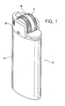
- lighter 10 according to the present invention is shown having a protective guard 60 disposed above a portion of the striking wheel assembly.
- lighter 10 has body 12 with striking wheel assembly 14 rotatably disposed between spark-wheel supports 15 (shown partially in phantom in Fig. 2 ) via axle 16.
- Striking wheel assembly 14 is located at the top end of body 12 and comprises turning wheels 18 disposed on each side of rotary sparker 20.
- the two turning wheels 18 and sparker 20 are connected to one another, and are mounted coaxially on axle 16.
- Axle 16 is supported on apertures 76 defined on spark-wheel supports 15.
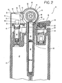
- Body 12 defines a cylindrical cavity 22 positioned longitudinally and centrally within body 12. Flint 24 is disposed within cavity 22, and is urged into frictional contact with rotary sparker 20 by spring 26.
- lighter 10 further comprises a depressible valve actuator 28, which is pivotally mounted on body 12 through tabs 30, which are located below axle 16, as shown in Figs. 2 .
- valve actuator 28 defines slot 32 at one end.
- Thumb pad 36 (shown in Figs. 2-4 ) is attached to valve actuator 28 in cooperation with aperture 33 by crimping, press fitting or by means of a plastic rivet.
- valve actuator 28 defines an opening 37, which allows flint 24 to extend from lighter body 12 through valve actuator 28 to reach rotary sparker 20.
- Valve 40 controls the release of fuel from reservoir 42.
- valve 40 is a normally open valve, forced open by the pressure of fuel within reservoir 42.
- valve actuator 28 acts on valve 40 to maintain it in a closed position.
- Compression spring 44 pushes up on a first end of valve actuator 28, forcing the second, opposite end to act downwardly on valve 40 where it extends through slot 32. This pressure maintains the valve in a closed position until thumb pad 36 is sufficiently depressed allowing the nozzle 43 of valve 40 to be lifted and thereby releasing the fuel.
- Second compression spring 46 acts between the valve actuator and valve stem to prevent release of fuel before the thumb pad is depressed to a sufficiently actuated position.
- a normally closed valve which is forced open by the lifting of the second end of the valve actuator due to depression of the thumb pad may be utilized.
- Lighter 10 also has windbreaking shield 50 mounted on top of body 12 enclosing the spark-wheel supports 15 and around valve 40, as shown in Fig. 2 .
- Shield 50 assists in the generation and maintenance of the flame.
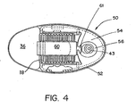
- shield 50 comprises body portion 52 and cover portion 54 defining flame aperture 56.
- an arcuate guard 60 is shaped and dimensioned to fit over the rotary sparker 20, and to be positioned radially beyond and above the turning wheels 18. However, the width of guard 60 is such that it extends between but preferably not over wheels 18. Guard 60 is preferably elevated above the surfaces of the turning wheels 18, such that guard 60 should be depressed before turning wheels 18 can be rotated. Guard 60 comprises at least one retaining member 61, an arcuate body portion 62 and an end member 63. End member 63 is received in body cavity 64, which is disposed adjacent to the wall of flint cavity 22 (for clarity in Fig. 2 body cavity 64 and end 63 are not shown to scale with respect to each other).
- Body cavity 64 can be positioned either above or below valve actuator 28. If body cavity 64 is positioned below the valve actuator, end member 63 is inserted through opening 37 defined on valve actuator 28 to be inserted in body cavity 64. To further resist the removal of guard 60, at least one lance member 66 is provided proximate to end member 63 and is oriented generally in an upward direction. Preferably two lance members are provided, and the tips of lance members 66 are positioned immediately adjacent to the wall of flint cavity 22 to assist in alignment and resist upward movement of guard 60.
- Retaining member 61 cooperates with cover portion 54 of windbreaking shield 50 to retain guard 60 to the lighter.
- retaining member 61 has an upturning hook and is tucked under cover portion 54 of shield 50 as shown in Figs. 2 and 4 .
- guard 60 is in its undepressed state.
- F1 is first applied to guard 60 to partially move it to a position where turning wheels 18 can be manipulated.
- F2 is then applied to rotate the turning wheels 18 to produce the spark.
- F3 is then applied to depress thumb pad 36 of valve actuator 28 to actuate valve 40 to release the fuel to be ignited by the produced spark.
- guard 60 it is not necessary to deform guard 60. If guard 60 is positioned such that the fleshy, pulp portion of the adult user's finger is sufficient to extend over and around guard portion 60, the adult's finger can contact turning wheels 18 for rotation without such deformation. Preferably, rotation of the turning wheels would be a result of a combination of both types of action, i . e ., the deformation of the guard and neck and the extension of the adult finger partially around the guard. It has been found that a guard made of stainless steel hardened to a hardness approximate to a Rockwell C-35 hardness, with a thickness of about 0.016 inch (0.4 mm), provides satisfactory results. As will be appreciated by persons of ordinary skill in the art, other materials, hardnesses and thicknesses may be used. Based on the teachings of the present invention as set forth herein, a person of ordinary skill in the art could adapt the present invention as desired.
- Rotation of the turning wheels 18 causes a spark to be produced in a conventional manner.
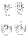
- the user's finger depresses the thumb pad 36 on the valve actuator 28 to actuate a release of fuel from the valve 40.
- This action occurs after the creation of the spark, as shown in Fig. 12 (A)-(D) .
- the spark created is large enough to ignite the fuel even though it is normally not released until a period of time after the creation of the spark.
- the lighter as described above increases the difficulty of operation by children under five years of age, who do not have sufficient coordination, digit size or strength to operate the present invention as described.
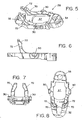
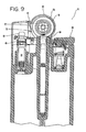
- At least one blocking member 70 is provided on valve actuator 28.
- two blocking members are disposed between slot 32 and tabs 30, as shown in Figs. 5-8 .
- Each blocking member 70 is angled generally upward and has clearance surface 72 disposed at the top of the blocking member.
- Blocking members 70 are configured and dimensioned to physically engage retaining member 61 of guard 60 once valve actuator 28 is depressed as shown by comparing Fig. 2 to Fig. 9 .
- clearance surface 72 is provided on blocking members 70 to provide clearance for the downward movement of retaining member 61 so that the downward movement of guard 60 is unimpeded.
- the present invention provides floating tab apertures 78, as shown in Figs. 10 and 11 .
- Tab apertures 78 have generally an oval shape with a minor axis and a major axis, and are dimensioned to be larger than tabs 30 of valve actuator 28, such that tabs 30 are generally movable within floating tab apertures 78.
- the shape of floating tab apertures 78 controls the movement of valve actuator 28.
- apertures 78 are orientating in a vertical direction.
- the major axis of aperture 78 is parallel to a longitudinal axis of the lighter body 12.
- valve actuator 28 is movable in the vertical direction.
- Spring 44 tends to push valve actuator 28 upward and therefore tabs 30 are normally positioned at the top of the floating tab apertures.
- valve actuator 28 can be resiliently moved downward against spring 44 to create more room for the assembly of spark wheel assembly 14 and guard 60. It is preferred that floating tab apertures 78 are provided on lighter body 12 when valve actuator 28 is equipped with blocking members 70, because the configuration and dimension of the blocking members along with the close proximity of the blocking members to the spark wheel assembly 14 and guard 60 can interfere with the assembly of the spark wheel assembly 14, guard 60 and shield 50.
Landscapes
- Engineering & Computer Science (AREA)
- Chemical & Material Sciences (AREA)
- Combustion & Propulsion (AREA)
- Mechanical Engineering (AREA)
- General Engineering & Computer Science (AREA)
- Lighters Containing Fuel (AREA)
- Road Signs Or Road Markings (AREA)
- Gas-Insulated Switchgears (AREA)
- Control Of Combustion (AREA)
Claims (9)
- Feuerzeug (10) umfassend:ein Feueizeugaehäuse (12), das einen Brennstoffspeicher (42) enthält, der in Verbindung mit einem Ventil (40) zum Freigeben von Brennstoff aus ihm steht;funkenerzeugendes Element (20), das durch einen Benutzer drehbar ist, um auf das Ventil (40) gerichtete Funken zu erzeugen, wobei das Element (20) so an dem Gehäuse (12) angeordnet ist, dass mindestens ein Teildavon zur Betätigung und Drehung durch den Benutzer freiliegend ist;ein Schutzteil (60), das an dem Feuerzeug (10) angeordnet ist und sich mindestens um den freiliegenden Teil des funkenerzeugenden Elements (20) erstreckt, wobei das Schutzteil (60) radial außerhalb desfunkenerzeugenden Elements (20) angeordnet ist und in eine Stellung niederdrückbar ist, die die Betätigung des funkenerzeugenden Elements (20) gestattet;eine Ventilbetätigungsvorrichtung (28), die niederdrückbar ist, um das Ventil (40) zu betätigen und den Brennstoff freizugeben, und einen Blockierteil (70), das mit der Ventilbetätigungsvorrichtung (28)zusammenwirkt, um dem Niederdrücken des Schutzteils (60) nach dem Niederdrücken der Ventilbetätigungsvorrichtung (28) einen Widerstand entgegenzusetzen.
- Feuerzeug (10) nach Anspruch 1, bei dem das Schutzteil (60) ein erstes Ende (63) aufweist, wobei das erste Ende (63) in einem Hohlraum (64) in dem Feuerzeuggehäuse (12) aufgenommen ist.
- Feuerzeug (10) nach Anspruch 2, bei dem das Schutzteil (60) ferner mindestens eine Lanze (66) aufweist, die in der Nähe des ersten Endes (63) angeordnet ist, wobei die Lanze (66) mit einem Teil des Feuerzeuggehäuses (12) zusammenwirkt, um einer relativen Bewegung zwischen dem ersten Ende (63) und dem Feuerzeuggehäuse (12) einen Widerstand entgegenzusetzen.
- Feuerzeug (10) nach Anspruch 1, bei dem:die Ventilbetätigungsvorrichtung (28) einen Hebel aufweist, der um einen Punkt in der Nähe des funkenerzeugenden Elements (20) drehbar ist, wobei ein erstes Ende von einem Benutzer niederdrückbar ist und ein zweites Ende als Antwort darauf anhebbar ist, um das Ventil (40) zu betätigen; unddas Blockierteil (70) mindestens einen hochstehenden Teil aufweist, der an dem drehbaren Hebel zwischen dem zweiten Ende und dem Drehpunkt angeordnet ist, derart, dass das Niederdrücken des ersten Endes bewirkt, dass das Blockierteil (70) sich an einen Ort bewegt, wo es in der Lage ist, das Niederdrücken des Schutzteils (60) einzuschränken.
- Feuerzeug (10) nach Anspruch 4, bei dem der hochstehende Teil des Blockierteils (70) eine Freiraumfläche (72) aufweist, die an demselben derart definiert ist, dass vor dem Niederdrücken der Ventilbetätigungsvorrichtung (28) das Schutzteil (60) in die Stellung niederdrückbar ist, die Betätigung gestattet.
- Feuerzeug (10) nach Anspruch 1, bei dem die Ventilbetätigungsvorrichtung (28) einen Drehhebel umfasst, der Zungen (30) aufweist, die darauf angeordnet sind und die Zungen in Öffnungen (78) aufgenommen sind, die an dem Feuerzeuggehäuse (12) definiert sind, derart, dass die Ventilbetätigungsvorrichtung (28) drehbar in den Öffnungen (78) abgestützt ist und innerhalb der Öffnungen (78) bewegbar ist.
- Feuerzeug (10) nach Anspruch 1, bei dem:die Ventilbetätigungsvorrichtung (28) einen Hebel aufweist, der um einen Punkt in der Nähe des funkenerzeugenden Elements (20) drehbar ist, wobei ein erstens Ende von einem Benutzer niederdrückbar ist und ein zweites Ende als Antwort darauf anhebbar ist, um das Ventil (40) zu betätigen; unddas Blockierteil (70) mindestens einen hochstehenden Teil aufweiset, der an dem drehbaren Hebel zwischen dem zweiten Ende und dem Drehpunkt derart angeordnet ist, dass das Niederdrücken des ersten Endes bewirkt, dass das Blockierteil (70) an dem Schutzteil (60) angreift.
- Feuerzeug (10) nach Anspruch 1, bei dem die Ventilbetätigungsvorrichtung (28) Zungen (30) umfasst, die geeignet sind, in den entsprechenden Zungenöffnungen (78), die auf dem Feuerzeuggehäuse (12) definiert sind, aufgenommen zu werden, so dass die Ventilbetätigungsvorrichtung (28) drehbar und bewegbar von den Zungenöffnungen (78) gestützt wird.
- Feuerzeug (10) nach Anspruch 8, bei dem die Zungenöffnungen (78) im Allgemeinen eine ovale Form aufweisen mit einer kleinen Achse und einer großen Achse, wobei die große Achse parallel zu einer Längsrichtung des Feuerzeuggehäuses (12) ist.
Applications Claiming Priority (3)
| Application Number | Priority Date | Filing Date | Title |
|---|---|---|---|
| US09/061,911 US5957680A (en) | 1998-04-17 | 1998-04-17 | Lighter having a guard member and cooperating blocking members |
| US61911 | 1998-04-17 | ||
| PCT/US1999/008336 WO1999054661A1 (en) | 1998-04-17 | 1999-04-16 | Lighter having guard member and blocking members |
Publications (3)
| Publication Number | Publication Date |
|---|---|
| EP1105677A1 EP1105677A1 (de) | 2001-06-13 |
| EP1105677A4 EP1105677A4 (de) | 2008-04-16 |
| EP1105677B1 true EP1105677B1 (de) | 2009-09-16 |
Family
ID=22038942
Family Applications (1)
| Application Number | Title | Priority Date | Filing Date |
|---|---|---|---|
| EP99918597A Expired - Lifetime EP1105677B1 (de) | 1998-04-17 | 1999-04-16 | Anzünder mit schutz- und blockiervorrichtung |
Country Status (10)
| Country | Link |
|---|---|
| US (1) | US5957680A (de) |
| EP (1) | EP1105677B1 (de) |
| AT (1) | ATE443235T1 (de) |
| AU (1) | AU762305B2 (de) |
| CA (1) | CA2340061C (de) |
| DE (2) | DE69941434D1 (de) |
| ES (1) | ES2168239T3 (de) |
| MY (1) | MY114636A (de) |
| TW (1) | TW587673U (de) |
| WO (1) | WO1999054661A1 (de) |
Families Citing this family (16)
| Publication number | Priority date | Publication date | Assignee | Title |
|---|---|---|---|---|
| USD425656S (en) * | 1999-03-19 | 2000-05-23 | Ronson Corporation | Lighter |
| FR2799531B1 (fr) * | 1999-10-12 | 2002-02-08 | Hameur | Briquet a allumage phyrophorique |
| GB2359875B (en) * | 2000-03-02 | 2002-01-16 | Swedish Match Lighters Bv | Child resistant gas lighters |
| US6485291B2 (en) * | 2001-01-11 | 2002-11-26 | Bic Corporation | Covered spark-generating device for a lighter with engageable manipulable member |
| GB0104622D0 (en) | 2001-02-24 | 2001-04-11 | Swedish Match Lighters Bv | Child resistant gas lighters |
| US6837705B2 (en) * | 2001-02-24 | 2005-01-04 | Swedish Matach Lighters B.V. | Child resistant gas lighters |
| KR20030018251A (ko) * | 2001-08-27 | 2003-03-06 | 전종구 | 브레이크 휠이 구비된 안전 가스라이타 |
| USD480173S1 (en) | 2001-12-10 | 2003-09-30 | Kin Chung Li | Disposable lady lighter |
| CN2685727Y (zh) * | 2004-01-07 | 2005-03-16 | 黄新华 | 带保险杆的砂轮打火机 |
| EP2447165A1 (de) | 2005-02-16 | 2012-05-02 | Société BIC | Brennstoffzufuhrsysteme mit Betriebswiderstand |
| USD587843S1 (en) * | 2008-07-07 | 2009-03-03 | Xinhua Huang | Gas lighter |
| US8653942B2 (en) | 2008-08-20 | 2014-02-18 | John Gibson Enterprises, Inc. | Portable biometric lighter |
| US10502419B2 (en) | 2017-09-12 | 2019-12-10 | John Gibson Enterprises, Inc. | Portable biometric lighter |
| USD949461S1 (en) * | 2020-10-05 | 2022-04-19 | KCI Newport, Inc. | Lighter |
| USD973264S1 (en) * | 2021-03-08 | 2022-12-20 | Vpr Brands, Lp | Pocket lighter |
| USD1048537S1 (en) * | 2023-07-07 | 2024-10-22 | Dan Beal | Smoking storage device |
Family Cites Families (8)
| Publication number | Priority date | Publication date | Assignee | Title |
|---|---|---|---|---|
| US5456598A (en) * | 1988-09-02 | 1995-10-10 | Bic Corporation | Selectively actuatable lighter |
| US5431558A (en) * | 1988-09-02 | 1995-07-11 | Bic Corporation | Selectively actuatable lighter |
| US5085578A (en) * | 1989-10-16 | 1992-02-04 | Hunter Robert M | Child-resistant lighter with gas and spark control |
| US5197870A (en) * | 1992-01-29 | 1993-03-30 | Yang James C H | Safety lighter |
| US5271731A (en) * | 1992-12-16 | 1993-12-21 | Hsin Chung Pan | Automatically lockable safety lighter |
| US5520197A (en) * | 1993-07-28 | 1996-05-28 | Bic Corporation | Lighter with guard |
| US5483978A (en) * | 1993-07-28 | 1996-01-16 | Bic Corporation | Lighter with guard |
| ES2113237B1 (es) * | 1994-03-11 | 1999-01-01 | Flamagas | Encendedor de bolsillo. |
-
1998
- 1998-04-17 US US09/061,911 patent/US5957680A/en not_active Expired - Lifetime
-
1999
- 1999-04-16 MY MYPI99001483A patent/MY114636A/en unknown
- 1999-04-16 EP EP99918597A patent/EP1105677B1/de not_active Expired - Lifetime
- 1999-04-16 AU AU36473/99A patent/AU762305B2/en not_active Expired
- 1999-04-16 ES ES99918597T patent/ES2168239T3/es not_active Expired - Lifetime
- 1999-04-16 AT AT99918597T patent/ATE443235T1/de not_active IP Right Cessation
- 1999-04-16 WO PCT/US1999/008336 patent/WO1999054661A1/en not_active Ceased
- 1999-04-16 DE DE69941434T patent/DE69941434D1/de not_active Expired - Lifetime
- 1999-04-16 CA CA002340061A patent/CA2340061C/en not_active Expired - Lifetime
- 1999-04-16 DE DE1105677T patent/DE1105677T1/de active Pending
- 1999-05-04 TW TW093201193U patent/TW587673U/zh not_active IP Right Cessation
Also Published As
| Publication number | Publication date |
|---|---|
| TW587673U (en) | 2004-05-11 |
| ATE443235T1 (de) | 2009-10-15 |
| DE69941434D1 (de) | 2009-10-29 |
| ES2168239T3 (es) | 2009-12-23 |
| AU3647399A (en) | 1999-11-08 |
| EP1105677A1 (de) | 2001-06-13 |
| ES2168239T1 (es) | 2002-06-16 |
| EP1105677A4 (de) | 2008-04-16 |
| CA2340061C (en) | 2009-03-24 |
| WO1999054661A1 (en) | 1999-10-28 |
| CA2340061A1 (en) | 1999-10-28 |
| US5957680A (en) | 1999-09-28 |
| HK1038054A1 (en) | 2002-03-01 |
| AU762305B2 (en) | 2003-06-19 |
| DE1105677T1 (de) | 2002-06-13 |
| MY114636A (en) | 2002-11-30 |
Similar Documents
| Publication | Publication Date | Title |
|---|---|---|
| EP0961080B1 (de) | Feuerzeug mit Schutzvorrichtung | |
| EP1105677B1 (de) | Anzünder mit schutz- und blockiervorrichtung | |
| JP4422341B2 (ja) | 子供の使用を阻止するライター | |
| EP0883780B1 (de) | Feuerzeug mit funkenrad-gleitring | |
| US5769098A (en) | Lighter with looped guard | |
| US5607295A (en) | Safety lock cigarette lighter | |
| HK1038054B (en) | Lighter having guard member and blocking members | |
| HK1023613B (en) | Lighter with guard | |
| HK1011072B (en) | Lighter with guard | |
| HK1009841B (en) | Lighter with looped guard | |
| CA2501765C (en) | Lighter with spark-wheel slip ring | |
| MXPA97009378A (en) | Lighter with liner protector |
Legal Events
| Date | Code | Title | Description |
|---|---|---|---|
| PUAI | Public reference made under article 153(3) epc to a published international application that has entered the european phase |
Free format text: ORIGINAL CODE: 0009012 |
|
| 17P | Request for examination filed |
Effective date: 20010216 |
|
| AK | Designated contracting states |
Kind code of ref document: A1 Designated state(s): AT BE CH CY DE DK ES FI FR GB GR IE IT LI LU MC NL PT SE |
|
| EL | Fr: translation of claims filed | ||
| TCAT | At: translation of patent claims filed | ||
| REG | Reference to a national code |
Ref country code: GR Ref legal event code: PP Ref document number: 20020300011 Country of ref document: GR |
|
| DET | De: translation of patent claims | ||
| REG | Reference to a national code |
Ref country code: ES Ref legal event code: BA2A Ref document number: 2168239 Country of ref document: ES Kind code of ref document: T1 |
|
| RAP1 | Party data changed (applicant data changed or rights of an application transferred) |
Owner name: BIC CORPORATION |
|
| A4 | Supplementary search report drawn up and despatched |
Effective date: 20080319 |
|
| 17Q | First examination report despatched |
Effective date: 20080709 |
|
| GRAP | Despatch of communication of intention to grant a patent |
Free format text: ORIGINAL CODE: EPIDOSNIGR1 |
|
| GRAS | Grant fee paid |
Free format text: ORIGINAL CODE: EPIDOSNIGR3 |
|
| GRAA | (expected) grant |
Free format text: ORIGINAL CODE: 0009210 |
|
| AK | Designated contracting states |
Kind code of ref document: B1 Designated state(s): AT BE CH CY DE DK ES FI FR GB GR IE IT LI LU MC NL PT SE |
|
| REG | Reference to a national code |
Ref country code: GB Ref legal event code: FG4D |
|
| REG | Reference to a national code |
Ref country code: CH Ref legal event code: EP |
|
| REG | Reference to a national code |
Ref country code: IE Ref legal event code: FG4D |
|
| REF | Corresponds to: |
Ref document number: 69941434 Country of ref document: DE Date of ref document: 20091029 Kind code of ref document: P |
|
| REG | Reference to a national code |
Ref country code: HK Ref legal event code: GR Ref document number: 1038054 Country of ref document: HK |
|
| REG | Reference to a national code |
Ref country code: ES Ref legal event code: FG2A Ref document number: 2168239 Country of ref document: ES Kind code of ref document: T3 |
|
| PG25 | Lapsed in a contracting state [announced via postgrant information from national office to epo] |
Ref country code: FI Free format text: LAPSE BECAUSE OF FAILURE TO SUBMIT A TRANSLATION OF THE DESCRIPTION OR TO PAY THE FEE WITHIN THE PRESCRIBED TIME-LIMIT Effective date: 20090916 |
|
| PG25 | Lapsed in a contracting state [announced via postgrant information from national office to epo] |
Ref country code: NL Free format text: LAPSE BECAUSE OF FAILURE TO SUBMIT A TRANSLATION OF THE DESCRIPTION OR TO PAY THE FEE WITHIN THE PRESCRIBED TIME-LIMIT Effective date: 20090916 |
|
| NLV1 | Nl: lapsed or annulled due to failure to fulfill the requirements of art. 29p and 29m of the patents act | ||
| PG25 | Lapsed in a contracting state [announced via postgrant information from national office to epo] |
Ref country code: CY Free format text: LAPSE BECAUSE OF FAILURE TO SUBMIT A TRANSLATION OF THE DESCRIPTION OR TO PAY THE FEE WITHIN THE PRESCRIBED TIME-LIMIT Effective date: 20090916 |
|
| PG25 | Lapsed in a contracting state [announced via postgrant information from national office to epo] |
Ref country code: PT Free format text: LAPSE BECAUSE OF FAILURE TO SUBMIT A TRANSLATION OF THE DESCRIPTION OR TO PAY THE FEE WITHIN THE PRESCRIBED TIME-LIMIT Effective date: 20100118 |
|
| PG25 | Lapsed in a contracting state [announced via postgrant information from national office to epo] |
Ref country code: BE Free format text: LAPSE BECAUSE OF FAILURE TO SUBMIT A TRANSLATION OF THE DESCRIPTION OR TO PAY THE FEE WITHIN THE PRESCRIBED TIME-LIMIT Effective date: 20090916 Ref country code: AT Free format text: LAPSE BECAUSE OF FAILURE TO SUBMIT A TRANSLATION OF THE DESCRIPTION OR TO PAY THE FEE WITHIN THE PRESCRIBED TIME-LIMIT Effective date: 20090916 |
|
| PLBE | No opposition filed within time limit |
Free format text: ORIGINAL CODE: 0009261 |
|
| STAA | Information on the status of an ep patent application or granted ep patent |
Free format text: STATUS: NO OPPOSITION FILED WITHIN TIME LIMIT |
|
| PG25 | Lapsed in a contracting state [announced via postgrant information from national office to epo] |
Ref country code: DK Free format text: LAPSE BECAUSE OF FAILURE TO SUBMIT A TRANSLATION OF THE DESCRIPTION OR TO PAY THE FEE WITHIN THE PRESCRIBED TIME-LIMIT Effective date: 20090916 |
|
| 26N | No opposition filed |
Effective date: 20100617 |
|
| PG25 | Lapsed in a contracting state [announced via postgrant information from national office to epo] |
Ref country code: GR Free format text: LAPSE BECAUSE OF FAILURE TO SUBMIT A TRANSLATION OF THE DESCRIPTION OR TO PAY THE FEE WITHIN THE PRESCRIBED TIME-LIMIT Effective date: 20091217 |
|
| PG25 | Lapsed in a contracting state [announced via postgrant information from national office to epo] |
Ref country code: IT Free format text: LAPSE BECAUSE OF FAILURE TO SUBMIT A TRANSLATION OF THE DESCRIPTION OR TO PAY THE FEE WITHIN THE PRESCRIBED TIME-LIMIT Effective date: 20090916 |
|
| PGFP | Annual fee paid to national office [announced via postgrant information from national office to epo] |
Ref country code: IE Payment date: 20110426 Year of fee payment: 13 Ref country code: LU Payment date: 20110504 Year of fee payment: 13 Ref country code: MC Payment date: 20110401 Year of fee payment: 13 Ref country code: CH Payment date: 20110425 Year of fee payment: 13 |
|
| PG25 | Lapsed in a contracting state [announced via postgrant information from national office to epo] |
Ref country code: MC Free format text: LAPSE BECAUSE OF NON-PAYMENT OF DUE FEES Effective date: 20120430 |
|
| REG | Reference to a national code |
Ref country code: CH Ref legal event code: PL |
|
| REG | Reference to a national code |
Ref country code: IE Ref legal event code: MM4A |
|
| PG25 | Lapsed in a contracting state [announced via postgrant information from national office to epo] |
Ref country code: LI Free format text: LAPSE BECAUSE OF NON-PAYMENT OF DUE FEES Effective date: 20120430 Ref country code: IE Free format text: LAPSE BECAUSE OF NON-PAYMENT OF DUE FEES Effective date: 20120416 Ref country code: CH Free format text: LAPSE BECAUSE OF NON-PAYMENT OF DUE FEES Effective date: 20120430 |
|
| PG25 | Lapsed in a contracting state [announced via postgrant information from national office to epo] |
Ref country code: SE Free format text: LAPSE BECAUSE OF FAILURE TO SUBMIT A TRANSLATION OF THE DESCRIPTION OR TO PAY THE FEE WITHIN THE PRESCRIBED TIME-LIMIT Effective date: 20090916 |
|
| PG25 | Lapsed in a contracting state [announced via postgrant information from national office to epo] |
Ref country code: LU Free format text: LAPSE BECAUSE OF NON-PAYMENT OF DUE FEES Effective date: 20120416 |
|
| REG | Reference to a national code |
Ref country code: FR Ref legal event code: PLFP Year of fee payment: 18 |
|
| REG | Reference to a national code |
Ref country code: FR Ref legal event code: PLFP Year of fee payment: 19 |
|
| REG | Reference to a national code |
Ref country code: DE Ref legal event code: R082 Ref document number: 69941434 Country of ref document: DE |
|
| REG | Reference to a national code |
Ref country code: FR Ref legal event code: PLFP Year of fee payment: 20 |
|
| PGFP | Annual fee paid to national office [announced via postgrant information from national office to epo] |
Ref country code: GB Payment date: 20180321 Year of fee payment: 20 |
|
| PGFP | Annual fee paid to national office [announced via postgrant information from national office to epo] |
Ref country code: FR Payment date: 20180322 Year of fee payment: 20 |
|
| PGFP | Annual fee paid to national office [announced via postgrant information from national office to epo] |
Ref country code: DE Payment date: 20180320 Year of fee payment: 20 Ref country code: ES Payment date: 20180504 Year of fee payment: 20 |
|
| REG | Reference to a national code |
Ref country code: DE Ref legal event code: R071 Ref document number: 69941434 Country of ref document: DE |
|
| REG | Reference to a national code |
Ref country code: GB Ref legal event code: PE20 Expiry date: 20190415 |
|
| PG25 | Lapsed in a contracting state [announced via postgrant information from national office to epo] |
Ref country code: GB Free format text: LAPSE BECAUSE OF EXPIRATION OF PROTECTION Effective date: 20190415 |
|
| REG | Reference to a national code |
Ref country code: ES Ref legal event code: FD2A Effective date: 20220126 |
|
| PG25 | Lapsed in a contracting state [announced via postgrant information from national office to epo] |
Ref country code: ES Free format text: LAPSE BECAUSE OF EXPIRATION OF PROTECTION Effective date: 20190417 |