EP1104501B1 - An adjustable size annular retaining assembly - Google Patents
An adjustable size annular retaining assembly Download PDFInfo
- Publication number
- EP1104501B1 EP1104501B1 EP99940347A EP99940347A EP1104501B1 EP 1104501 B1 EP1104501 B1 EP 1104501B1 EP 99940347 A EP99940347 A EP 99940347A EP 99940347 A EP99940347 A EP 99940347A EP 1104501 B1 EP1104501 B1 EP 1104501B1
- Authority
- EP
- European Patent Office
- Prior art keywords
- segments
- annular
- assembly
- assembly according
- segment
- Prior art date
- Legal status (The legal status is an assumption and is not a legal conclusion. Google has not performed a legal analysis and makes no representation as to the accuracy of the status listed.)
- Expired - Lifetime
Links
Images




Classifications
-
- F—MECHANICAL ENGINEERING; LIGHTING; HEATING; WEAPONS; BLASTING
- F16—ENGINEERING ELEMENTS AND UNITS; GENERAL MEASURES FOR PRODUCING AND MAINTAINING EFFECTIVE FUNCTIONING OF MACHINES OR INSTALLATIONS; THERMAL INSULATION IN GENERAL
- F16B—DEVICES FOR FASTENING OR SECURING CONSTRUCTIONAL ELEMENTS OR MACHINE PARTS TOGETHER, e.g. NAILS, BOLTS, CIRCLIPS, CLAMPS, CLIPS OR WEDGES; JOINTS OR JOINTING
- F16B21/00—Means for preventing relative axial movement of a pin, spigot, shaft or the like and a member surrounding it; Stud-and-socket releasable fastenings
- F16B21/10—Means for preventing relative axial movement of a pin, spigot, shaft or the like and a member surrounding it; Stud-and-socket releasable fastenings by separate parts
-
- B—PERFORMING OPERATIONS; TRANSPORTING
- B64—AIRCRAFT; AVIATION; COSMONAUTICS
- B64C—AEROPLANES; HELICOPTERS
- B64C25/00—Alighting gear
- B64C25/02—Undercarriages
- B64C25/08—Undercarriages non-fixed, e.g. jettisonable
- B64C25/10—Undercarriages non-fixed, e.g. jettisonable retractable, foldable, or the like
-
- B—PERFORMING OPERATIONS; TRANSPORTING
- B64—AIRCRAFT; AVIATION; COSMONAUTICS
- B64F—GROUND OR AIRCRAFT-CARRIER-DECK INSTALLATIONS SPECIALLY ADAPTED FOR USE IN CONNECTION WITH AIRCRAFT; DESIGNING, MANUFACTURING, ASSEMBLING, CLEANING, MAINTAINING OR REPAIRING AIRCRAFT, NOT OTHERWISE PROVIDED FOR; HANDLING, TRANSPORTING, TESTING OR INSPECTING AIRCRAFT COMPONENTS, NOT OTHERWISE PROVIDED FOR
- B64F5/00—Designing, manufacturing, assembling, cleaning, maintaining or repairing aircraft, not otherwise provided for; Handling, transporting, testing or inspecting aircraft components, not otherwise provided for
- B64F5/10—Manufacturing or assembling aircraft, e.g. jigs therefor
-
- F—MECHANICAL ENGINEERING; LIGHTING; HEATING; WEAPONS; BLASTING
- F16—ENGINEERING ELEMENTS AND UNITS; GENERAL MEASURES FOR PRODUCING AND MAINTAINING EFFECTIVE FUNCTIONING OF MACHINES OR INSTALLATIONS; THERMAL INSULATION IN GENERAL
- F16B—DEVICES FOR FASTENING OR SECURING CONSTRUCTIONAL ELEMENTS OR MACHINE PARTS TOGETHER, e.g. NAILS, BOLTS, CIRCLIPS, CLAMPS, CLIPS OR WEDGES; JOINTS OR JOINTING
- F16B2200/00—Constructional details of connections not covered for in other groups of this subclass
- F16B2200/40—Clamping arrangements where clamping parts are received in recesses of elements to be connected
- F16B2200/403—Threaded clamping parts
-
- F—MECHANICAL ENGINEERING; LIGHTING; HEATING; WEAPONS; BLASTING
- F16—ENGINEERING ELEMENTS AND UNITS; GENERAL MEASURES FOR PRODUCING AND MAINTAINING EFFECTIVE FUNCTIONING OF MACHINES OR INSTALLATIONS; THERMAL INSULATION IN GENERAL
- F16C—SHAFTS; FLEXIBLE SHAFTS; ELEMENTS OR CRANKSHAFT MECHANISMS; ROTARY BODIES OTHER THAN GEARING ELEMENTS; BEARINGS
- F16C35/00—Rigid support of bearing units; Housings, e.g. caps, covers
- F16C35/04—Rigid support of bearing units; Housings, e.g. caps, covers in the case of ball or roller bearings
- F16C35/06—Mounting or dismounting of ball or roller bearings; Fixing them onto shaft or in housing
- F16C35/067—Fixing them in a housing
Definitions
- This invention relates to an adjustable size annular retaining assembly suitable particularly, but not exclusively, for use in confined spaces.
- a retaining assembly of the kind described above, comprising at least two substantially annular substantially rigid segments, each of said at least two substantially annular substantially rigid segments including an inner threaded surface; and means for pivotably interconnecting the segments in an end to end relationship so that when the segments are pivotally interconnected at all but a single pair of adjoining segment ends the assembly can be contracted to a reduced size condition for insertion through or into or removal through or from a confined space, and expanded into a desired annular size condition for pivotal interconnection of said non-connected pair of adjoining segment ends.
- said at least two substantially annular substantially rigid segments are each arcuate in profile, of substantially identical projected diameter and of suitable circumferential length so as to form an annular ring in said expanded desired annular size condition.
- the segment pivotally interconnecting means are such, that when the segments are pivotally interconnected at all but a single pair of adjoining segment ends, as to permit, movement, in the case of two segments, between the two segments at the interconnected segment ends in and/or out of the plane of said segments, and in the case of three or more segments, between adjoining segments, at the interconnected segment ends in the plane of the segments.
- the assembly has two segments
- the segment pivotally interconnecting means includes a lug formation at each end of a first of the two segments, an axially extending internally threaded bore in one end and a lug formation at the other end of a second of the two segments, a connecting rod with a lug formation at one end thereof and which other end thereof is externally threaded for engagement with the correspondingly threaded bore of the second of said segments, for providing said out of plane movement between the two segments by relative rotation along the thread length between the connecting rod and second of said segments, said lug formations each having at least one bore therethrough transverse to the plane of the segments and rod respectively, and two or more interconnecting pins, insertable into the transverse bores, when axially aligned, of the lug formation of the connecting pin and one lug formation of the first of said segments, and of the other lug formation of the first of said segments and the adjoining lug formation of the second of said segments, for providing said in plane movement between the two segments by pivoting of said segment
- the first segment lug formations include at one end a forked portion, with the associated transverse bore extending therethrough, for engagement with the adjoining connecting rod lug formation, and at the other end a fork element which is offset relative to a fork element forming the lug formation of the second segment for pivotal interconnection therewith.
- the assembly includes pin retaining means for, when said assembly is in the expanded desired annular size condition with the interconnecting pins in the axially aligned transverse bores, engaging ends thereof so as to retain the pins in their bores.
- the pin retaining means includes at least two interfaces, provided by at least two substantially annular plates, removably attachable to the segments in the expanded desired annular size condition, and/or by adjoining housings when the assembly is operatingly associated therewith.
- At least one of said interconnecting pins is a threaded shank bolt and the transverse bore of the lug formation of the second of two segments is correspondingly threaded.
- the assembly has three or more segments
- the segment pivotally interconnecting means includes a lug formation at each end of each segment, each of which formations has a bore therethrough transverse to the plane of the segments, and three or more interconnecting pins, each insertable into the transverse bores, when axially aligned, of two adjoining segment end lug formations, for providing said in plane movement between adjoining segments by pivoting of said lug formations about the associated interconnecting pin.
- each lug formation includes at least one fork element, each having one of the associated transverse bores extending therethrough and being offset relative to the adjoining lug formation fork element or elements for pivotal interconnection therewith.
- each substantially annular segment is internally grooved throughout its length to provide an internal channel therealong.
- the assembly includes a substantially annular retaining spring for removable location in said internal channel when said assembly is in the expanded desired annular size condition with the interconnecting pins in the axially aligned transverse bores to engage adjacent ends of the pins and thus retain them in said bores.
- the assembly includes pin retaining means for engaging the pin ends remote from the ends engaged by the spring.
- the pin retaining means is an interface provided either by a substantially annular plate, removably attachable to the segments in the expanded desired annular size condition, or by an adjoining housing when the assembly is operatingly associated therewith.
- each substantially annular segment has a threaded surface so as to provide, in the expanded desired annular size condition of the assembly, a continuous or part continuous thread for receiving a threaded part to be removably connected to the assembly.
- the threaded surface is provided on an inner annular face of each substantially annular segment.
- one or more of the substantially annular segments has a locating key on an outer annular face thereof, for engagement, when said assembly is inserted into an external housing and assembled into said expanded desired annular size condition, with one or more corresponding grooves in said housing, thereby retaining said assembly in a fixed axial position while the threaded part initially engages with the thread surface of the substantially annular segments.
- one or more of the substantially annular segments has a tang on an outer annular face thereof, for engagement, when said assembly is inserted into an external housing and assembled into said expanded desired annular size condition, with one or more corresponding grooves in said housing, thereby providing resistance against a reactive moment induced by engagement of the threaded part into the thread surface of the substantially annular segments, so as to maintain a fixed polar position.
- the assembly has five substantially annular substantially rigid segments.
- an aircraft wing and landing gear assembly having at least one landing gear structure carried on a pintle in a bearing in a bore in a pintle housing in the wing, and including an adjustable size annular retaining assembly as hereinbefore described, in the expanded desired annular size condition, with the pintle and pintle housing to retain said bearing in the bore, and for insertion or removal through the bore in the reduced size condition.
- An adjustable size annular retaining assembly of the present invention as shown in Figures 1 to 17 of the accompanying drawings is intended for use in confined spaces and is particularly intended for use in the aerospace industry in artefacts such as aircraft.
- the landing gear leg is pivotally mounted on a pintle in a bearing in a bore in a pintle housing in the wing and retained therein by a bearing retaining nut during manufacture of the aircraft wing, and subsequent inspection or removal of the retaining nut is difficult.
- An adjustable size annular retaining assembly of the present invention may be used removably to retain the pintle bearing in the bore.
- an adjustable size annular retaining assembly includes at least two substantially annular, substantially rigid segments 1 and 2, and means 3,4 for pivotally interconnecting the segments in end to end relationship, so that when the segments are pivotally interconnected at all but a single pair of adjoining segment ends, 1b and 2b, the assembly can be contracted to a reduced size condition as shown generally at 5 in Figure 2, for insertion through or into or removal through or from a confined space 6, and expanded into a desired annular size condition as generally shown at 7 in Figure 1, for pivotal interconnection of said non-connected pair of adjoining segment ends 1b and 2b.
- the two substantially annular, substantially rigid segments 1, 2 are each arcuate in profile, of substantially identical projected diameter and of suitable circumferential length so as to form an annular ring in the desired annular size condition 7.
- the means 3, 4 for pivotally interconnecting the segments in end to end relationship afford movement in and/or out of the plane of the two segments 1, 2 as shown schematically by arrows 11a and 11b in Figure 1.
- the means 3, 4 are provided, as shown in Figures 1 to 6, by lug formations 1a and 1b at each end of segment 1, by an axially extending internally threaded bore 2a in one end of segment 2, by a lug formation 2b in the other end of segment 2, and by a connecting rod 8, with a lug formation 9 at one end, and an externally threaded shaft 10 at the other end.
- the threaded interface between the bore 2a and the shaft 10 as shown in Figure 3 permits the rotation indicated by arrow 11b in Figure 1, thus allowing movement between the two segments and out of the plane of the two segments.
- the lug formation 2b of segment 2 and the lug formation 1b of segment 1 as shown in Figure 6, the lug formation 1a of segment 1 and the lug formation 9 of connecting rod 8 as shown in Figure 3, have bores 12 therethrough transverse to the plane of the segments and rod respectively.
- the pivotal interconnection between segment 1 and the connecting rod 8 is provided by a pin 12b, which is a press and clearance fit through the aligned transverse bores 12 of lug formations 1a and 9 respectively, and which allows rotation therebetween as shown by arrow 11a in Figure 1 in the plane of the segments.
- the first segment lug formation 1a includes a forked portion 1c for engagement with a fork element 9a of the lug formation 9 of the connecting rod 8, as shown in Figures 3 and 4.
- the other lug formation 1b of the first segment 1 includes a fork element 1c, offset relative to and for engagement with a fork element 2c of the lug formation 2b of the second segment 2, as shown in Figures 5 and 6.
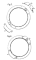
- Figures 7 and 8 show the removable attachment of two interface plates 14 forming part of the annular retaining assembly, whose attachment to the segments 1, 2 when the assembly is in the desired expanded condition with the interconnecting pins 12b, 13 in the axially aligned transverse bores 12 of the lug formations 1a and 9, 1b and 2b respectively, engage ends of the pins to retain the pins in their bores.
- the plates 14 may be secured to the segments in any convenient manner such as by screws (not shown) passing through holes 14a and 14b. Additional locking means, such as a locking wire, may be inserted into a hole 14c in one of the plates 14 to assist in securing the latter to bolt 13.
- Figure 9 of the accompanying drawings shows an adjustable size annular retaining assembly according to a second embodiment of the present invention including three substantially annular, substantially rigid segments 15, 16 and 17, and means 18 for pivotally interconnecting the segments in end to end relationship.
- the assembly can be contracted to a reduced size condition as shown generally at 5 in Figure 10, for insertion through or into or removal through or from a confined space 6, and expanded into a desired annular size condition as generally shown at 7 in Figure 9, for pivotal interconnection of said non-connected pair of adjoining segment ends 15b and 17b.
- the three substantially annular, substantially rigid segments 15, 16 and 17 are each arcuate in profile, of substantially identical projected diameter and of suitable circumferential length so as to form an annular ring in the desired annular size condition 7.
- FIG 11 of the accompanying drawings shows an adjustable size annular retaining assembly according to a third embodiment of the present invention including five substantially annular, substantially rigid segments 19, 20, 21, 22 and 23, and means 18 for pivotally interconnecting the segments in end to end relationship.
- the assembly can be contracted to a reduced size condition as shown generally at 5 in Figure 12, for insertion through or into or removal through or from a confined space 6, and expanded into a desired annular size condition as generally shown at 7 in Figure 11, for pivotal interconnection of said non-connected pair of adjoining segment ends 20a and 21a.
- each annular segment 19 to 23 are each arcuate in profile, of substantially identical projected diameter and of suitable circumferential length so as to form an annular ring in the desired annular size condition 7.
- each annular segment has a continuous thread on its inner annular face 30 as shown in Figure 11 to provide, in the desired annular size condition 7, a continuous thread for receiving a threaded part 28 to be removably connected to the assembly as shown in Figure 17.
- the pivotal interconnecting means are provided by lug formations 22a and 23a at each end of each segment, as shown in Figure 13, with bores 24 therethrough transverse to the plane of the segments as shown in Figure 15.
- the pivotal interconnection is provided by pins 24b, whose insertion into the axially aligned bores 24 of adjoining segments affords the in plane movement between the segments.
- Each lug formation of each segment includes two forked elements 22b, as shown in Figure 15, which are offset relative to the adjoining lug formation forked elements 23b of lug formation 23a for pivotal interconnection therewith.
- Each segment 15, 16, 17, 19, 20, 21, 22, 23 has an internally grooved channel 25 throughout its length, as shown schematically in Figures 11, 13, 15 and in end view in Figure 14.
- Figure 16 shows a substantially annular retaining spring 26 for removable location in the internal channels 25 of adjoining segments, whose insertion therein, when the assembly is in the desired expanded condition with the interconnecting pins 24b in the axially aligned transverse bores of the lug formations, engages adjacent ends of the pins 24b and thus retains the pins in their bores.
- one or more of the annular segments has a locating key 31 and a tang 32 on the outer annular face thereof.
- the keys 31 engage with one or more corresponding grooves 31b in the housing when the assembly is inserted into an external housing, shown generally at 27 in Figure 17.
- Element 28 in Figure 17 represents an externally threaded part, such as a bearing, to be removably connected to the assembly.
- the locating key 31 holds the assembly 7 steady so that the threaded surface 29 of element 28 can engage with the thread surface 30 of the substantially annular segments, and tang 32 provides a resistance against a subsequent reactive moment induced by the relative rotation between part 28 and the assembly 7.
- the procedure for insertion through or into a confined space 6, and expansion into a desired annular size condition 7 requires orientating the assembly parallel to the axis of the confined region, translating the assembly in its reduced size condition 5, which size reduction is achieved by manipulation of the pivotally interconnecting means 3 and 4, as hereinabove described, a 90 degree rotation of the reduced size assembly, then a reverse manipulation of the pivotally interconnecting means 3 and 4, to achieve the desired expanded annular size condition 7.
- segment ends 1b and 2b are interconnected by means of a threaded shank bolt 13, which bolt being inserted through the bore of lug formation 1b and into a correspondingly threaded bore of lug formation 2b, when said bores 12 are axially aligned.
- Interconnecting pin 12b inserted into the axially aligned transverse bores 12 of lug formations 9 and 1a, is held in place by annular interfaces 14, which are attached once the assembly has achieved the desired expanded annular size condition 7.
- the procedure for insertion through or into a confined space 6, and expansion into a desired annular size condition 7 is identical, due to the similar provision of in-plane movement between adjoining segments, and is described with reference to Figures 11 to 17, corresponding to the five segment embodiment.
- the procedure requires orientating the assembly perpendicular to the axis of the confined region 6, translating the assembly in its reduced size condition 5, which size reduction is achieved by a folding of segments 20 and 21 inside segments 19 and 22 as hereinabove described and shown in Figure 12, then a reverse manipulation of segments 19 to 23 to form an annular ring structure.
- the segment ends 20a and 21a are connected by a typical interconnecting pin 24b to complete the expanded desired annular size condition 7 of the assembly.
- each annular segment has an internal groove through its circumferential length 25, so as to provide a continuous channel through the assembly when in the desired expanded annular size condition 7.
- the annular diameter of this internal bore overlaps the interconnecting pins projected annulus, so that when the assembly is in the desired expanded annular size condition 7 and an annular retaining spring 26 is inserted in the internal channels 25 of successive segments, one of the two ends of the segment interconnecting pins 24b are engaged and retained in place.
- Figure 17 shows an assembly of the third embodiment of the present invention having passed through the region of confined space 6, assembled into its expanded desired annular size condition 7, and located in its associated housing 27, which for the present invention is a pintle housing for a main landing gear assembly in an aircraft wing.
- the present invention can be employed as a retaining assembly for a pintle bearing 28, whose external surface is threaded 29.
- the inner annular face of each annular segment 19 to 23, is correspondingly threaded 30, and two of the segments 19 and 22, have a key 31 on their outer annular faces, so as to locate the assembly into the pintle housing 27, and hold the assembly 7 steady so that the bearing 2B can initially engage therewith.
Landscapes
- Engineering & Computer Science (AREA)
- General Engineering & Computer Science (AREA)
- Mechanical Engineering (AREA)
- Aviation & Aerospace Engineering (AREA)
- Manufacturing & Machinery (AREA)
- Transportation (AREA)
- Pivots And Pivotal Connections (AREA)
- Lining And Supports For Tunnels (AREA)
- Snaps, Bayonet Connections, Set Pins, And Snap Rings (AREA)
- Clamps And Clips (AREA)
- Mutual Connection Of Rods And Tubes (AREA)
- General Details Of Gearings (AREA)
Description
Claims (13)
- An adjustable size annular retaining assembly for use in a confined space (6), the assembly comprising:-at least two substantially annular substantially rigid segments (1, 2; 15, 16, 17; 19, 20, 21, 22, 23), each of said at least two substantially annular substantially rigid segments (1, 2; 15, 16, 17; 19, 20, 21, 22, 23) including an inner threaded surface; andmeans (4; 18) for pivotably interconnecting the segments (1, 2; 15, 16, 17; 19, 20, 21, 22, 23) in an end to end relationship so that when the segments (1, 2; 15, 16, 17; 19, 20, 21, 22, 23) are pivotally interconnected at all but a single pair of adjoining segment ends (1b, 2b; 15b, 17b; 20a, 21a) the assembly can be contracted to a reduced size condition (5) for insertion through or into or removal through or from a confined space (6), and expanded into a desired annular size condition (7) for pivotal interconnection of said non-connected pair of adjoining segment ends (1b, 2b; 15b, 17b; 20a, 21a).
- An assembly according to claim 1, wherein said at least two substantially annular substantially rigid segments (1, 2; 15, 16, 17; 19, 20, 21, 22, 23) are each arcuate in profile, of substantially identical projected diameter and of suitable circumferential length so as to form an annular ring in said expanded desired annular size condition (7).
- An assembly according to claim 1 or 2, wherein, in said reduced size condition (5), the means (4; 18) for pivotably interconnecting the segments (1, 2; 15, 16, 17; 19, 20, 21, 22, 23) are such, that when the segments (1, 2; 15, 16, 17; 19, 20, 21, 22, 23) are pivotably interconnected at all but a single pair of adjoining segment ends (1b, 2b; 15b, 16b; 20a, 21a), as to permit, movement, in the case of two segments (1, 2), between the two segments (1, 2) at the interconnected segment ends (1a, 2a) in and out of the plane of said segments (1, 2), and in the case of three or more segments (15, 16, 17; 19, 20, 21, 22, 23), between adjoining segments (15, 16, 17; 19, 20, 21, 22, 23), at the interconnected segment ends in the plane of the segments (15, 16, 17; 19, 20, 21, 22, 23).
- An assembly according to claim 3, having three or more segments (15, 16, 17; 19, 20, 21, 22, 23), wherein the means (18) for pivotably interconnecting the segments (15, 16, 17; 19, 20, 21, 22, 23) includes a lug formation (22a, 23a) at each end of each segment (15, 16, 17; 19, 20, 21, 22, 23), each lug formation having a bore (24) therethrough transverse to the plane of the segments (15, 16, 17; 19, 20, 21, 22, 23), and three or more interconnecting pins (24b), each insertable into the transverse bores (24), when axially aligned, of two adjoining segment end lug formations (22a, 23a), for providing said in plane movement between adjoining segments (15, 16, 17; 19, 20, 21, 22, 23) by pivoting of said lug formations (22a, 23a) about the associated interconnecting pin (24b).
- An assembly according to claim 4, wherein each lug formation (23a) includes at least one fork element (23b), each having one of the associated transverse bores (24) extending therethrough and being offset relative to the adjoining lug formation fork element or elements (23b) for pivotal interconnection therewith.
- An assembly according to claim 5, wherein each substantially annular segment (15, 16, 17; 19, 20, 21, 22, 23) is internally grooved throughout its length to provide an internal channel (25) therealong.
- An assembly according to claim 6, further including a retaining spring element (26) for insertion into the internal channel (25) in each of the annular segments (15, 16, 17; 19, 20, 21, 22, 23).
- An assembly according to any one of the preceding claims, wherein the threaded surface comprises a continuous or part continuous thread for receiving a threaded part (13) to be removably connected to the assembly.
- An assembly according to claim 8, wherein the threaded surface is provided on an inner annular face of each substantially annular segment.
- An assembly according to claim 12, having five substantially annular substantially rigid segments.
- An assembly according to any one of the preceding claims, wherein one or more of the substantially annular segments (19, 20, 21, 22, 23) has a tang (32) on an outer annular face thereof, for engagement, when said assembly is inserted into an external housing and assembled into said expanded desired annular size condition (7), with one or more corresponding grooves in said housing, thereby providing resistance against a reactive moment induced by engagement of the threaded part into the thread surface of the substantially annular segments (19, 20, 21, 22, 23) so as to maintain a fixed polar position.
- An assembly according to claim 11, wherein one or more of the substantially annular segments (19, 20, 21, 22, 23) has a key (31) on an outer annular face thereof for engagement with the external housing when the assembly is in said expanded desired annular sized condition (7).
- An aircraft wing and landing gear assembly having at least one landing gear structure including a pintle housing (27) in the wing, and including an adjustable size annular retaining assembly according to any one of the preceding claims for mounting a pintle bearing (28) within the pintle housing (27).
Applications Claiming Priority (3)
| Application Number | Priority Date | Filing Date | Title |
|---|---|---|---|
| GBGB9818084.7A GB9818084D0 (en) | 1998-08-20 | 1998-08-20 | An adjustable size annular retaining assembly |
| GB9818084 | 1998-08-20 | ||
| PCT/GB1999/002718 WO2000011357A1 (en) | 1998-08-20 | 1999-08-17 | An adjustable size annular retaining assembly |
Publications (2)
| Publication Number | Publication Date |
|---|---|
| EP1104501A1 EP1104501A1 (en) | 2001-06-06 |
| EP1104501B1 true EP1104501B1 (en) | 2003-10-29 |
Family
ID=10837517
Family Applications (1)
| Application Number | Title | Priority Date | Filing Date |
|---|---|---|---|
| EP99940347A Expired - Lifetime EP1104501B1 (en) | 1998-08-20 | 1999-08-17 | An adjustable size annular retaining assembly |
Country Status (10)
| Country | Link |
|---|---|
| US (1) | US6368007B1 (en) |
| EP (1) | EP1104501B1 (en) |
| JP (1) | JP3679135B2 (en) |
| AU (1) | AU5434299A (en) |
| BR (1) | BR9913094A (en) |
| CA (1) | CA2341204C (en) |
| DE (1) | DE69912439T2 (en) |
| ES (1) | ES2205870T3 (en) |
| GB (1) | GB9818084D0 (en) |
| WO (1) | WO2000011357A1 (en) |
Families Citing this family (3)
| Publication number | Priority date | Publication date | Assignee | Title |
|---|---|---|---|---|
| US8231152B2 (en) * | 2010-08-31 | 2012-07-31 | Kerry A Carlson | Hatch latch |
| CN103831754B (en) * | 2014-02-26 | 2016-03-23 | 中冶华天工程技术有限公司 | Opposite position limiting structure |
| US11466934B2 (en) * | 2020-01-22 | 2022-10-11 | Anthony Nardella | Hinged kiln brick protective collar |
Family Cites Families (13)
| Publication number | Priority date | Publication date | Assignee | Title |
|---|---|---|---|---|
| US744917A (en) * | 1902-11-18 | 1903-11-24 | William Houldsworth | Roller-bearing. |
| US1885128A (en) * | 1930-04-21 | 1932-11-01 | Stonewall J Montgomery | Load binder |
| GB403628A (en) | 1932-06-17 | 1933-12-18 | Specialloid Ltd | Improvements in or relating to devices for retaining gudgeon pins in position |
| US2267252A (en) * | 1940-11-19 | 1941-12-23 | Ellis C Harlin | Hose coupling |
| US4083613A (en) * | 1977-02-11 | 1978-04-11 | Caterpillar Tractor Co. | Retainer for resiliently loading a bearing |
| US4123095A (en) * | 1977-06-30 | 1978-10-31 | Hansted Corporation | Pipe clamp having an overcenter toggle |
| US4189251A (en) * | 1978-12-13 | 1980-02-19 | Bianco Romolo P | Expandable annular locking device for a shaft |
| US4200407A (en) * | 1979-04-18 | 1980-04-29 | Bianco Romolo P | Bolted annular locking collar for a shaft |
| US4328939A (en) * | 1979-12-26 | 1982-05-11 | The Boeing Company | Airplane main landing gear assembly |
| CS271380B1 (en) * | 1988-08-31 | 1990-09-12 | Vaclav Hladky | Rolling machine with working rolls' quick-change |
| US5069571A (en) * | 1990-02-07 | 1991-12-03 | Seals-It, Inc. | Rod end assembly |
| US5411337A (en) * | 1994-04-26 | 1995-05-02 | Anlock Products And Machine Co. | Axially guided locking ring assembly |
| GB2320002A (en) * | 1996-12-04 | 1998-06-10 | British Aerospace | Aircraft landing gear arrangement |
-
1998
- 1998-08-20 GB GBGB9818084.7A patent/GB9818084D0/en not_active Ceased
-
1999
- 1999-08-17 WO PCT/GB1999/002718 patent/WO2000011357A1/en not_active Ceased
- 1999-08-17 CA CA002341204A patent/CA2341204C/en not_active Expired - Fee Related
- 1999-08-17 BR BR9913094-7A patent/BR9913094A/en not_active IP Right Cessation
- 1999-08-17 DE DE69912439T patent/DE69912439T2/en not_active Expired - Lifetime
- 1999-08-17 EP EP99940347A patent/EP1104501B1/en not_active Expired - Lifetime
- 1999-08-17 ES ES99940347T patent/ES2205870T3/en not_active Expired - Lifetime
- 1999-08-17 AU AU54342/99A patent/AU5434299A/en not_active Abandoned
- 1999-08-17 JP JP55768399A patent/JP3679135B2/en not_active Expired - Fee Related
- 1999-11-05 US US09/434,469 patent/US6368007B1/en not_active Expired - Lifetime
Also Published As
| Publication number | Publication date |
|---|---|
| JP2001508859A (en) | 2001-07-03 |
| EP1104501A1 (en) | 2001-06-06 |
| WO2000011357A1 (en) | 2000-03-02 |
| ES2205870T3 (en) | 2004-05-01 |
| BR9913094A (en) | 2001-05-08 |
| AU5434299A (en) | 2000-03-14 |
| CA2341204A1 (en) | 2000-03-02 |
| CA2341204C (en) | 2007-07-17 |
| JP3679135B2 (en) | 2005-08-03 |
| DE69912439D1 (en) | 2003-12-04 |
| US6368007B1 (en) | 2002-04-09 |
| DE69912439T2 (en) | 2004-05-06 |
| GB9818084D0 (en) | 1998-10-14 |
Similar Documents
| Publication | Publication Date | Title |
|---|---|---|
| US5702196A (en) | Turnbuckle-type adjustable link | |
| US4679961A (en) | Coupling mechanism | |
| KR100524037B1 (en) | Shim lock/pin anti-rotation bumper design | |
| US10612319B2 (en) | Radial ratchet dog anti-rotation device | |
| JPH086731B2 (en) | Frame structure assembly bar connecting tool | |
| US5551794A (en) | Swivel link | |
| US11035505B2 (en) | System, method and apparatus for in-line removable pipe assembly | |
| US2381697A (en) | Hub structure | |
| EP3771839B1 (en) | Nut locking assembly | |
| US3866650A (en) | Internal locking device | |
| CA2341204C (en) | An adjustable size annular retaining assembly | |
| USRE33438E (en) | Coupling mechanism | |
| GB2283294A (en) | Ceramic fasteners | |
| HU194975B (en) | Bayonet trunnion particularly for fastening the internal cylinder of hydraulic roll bearing remover on roll neck | |
| EP3473873B1 (en) | Threaded couplings with locking | |
| US20230382544A1 (en) | Adjustable support links for aircraft | |
| EP0632205B1 (en) | Device for joining two parts | |
| CA1281534C (en) | Method of manufacturing a rotor | |
| WO2000011359A1 (en) | A variable length shaft assembly | |
| RU2740147C1 (en) | Boltless gapless connection of flanges | |
| EP4481219B1 (en) | Locking differential thread | |
| CN112739888A (en) | Removable support interface for an annular turbine casing | |
| EP4522833B1 (en) | Cylinder lock and method for mounting such a cylinder lock | |
| US20260092504A1 (en) | Flexible coupling arrangement for directional drilling system | |
| CA3265894A1 (en) | Flexible Coupling Arrangement for Directional Drilling System |
Legal Events
| Date | Code | Title | Description |
|---|---|---|---|
| PUAI | Public reference made under article 153(3) epc to a published international application that has entered the european phase |
Free format text: ORIGINAL CODE: 0009012 |
|
| 17P | Request for examination filed |
Effective date: 20010214 |
|
| AK | Designated contracting states |
Kind code of ref document: A1 Designated state(s): AT BE CH CY DE DK ES FI FR GB GR IE IT LI LU MC NL PT SE Kind code of ref document: A1 Designated state(s): BE DE ES FR GB IT |
|
| GRAG | Despatch of communication of intention to grant |
Free format text: ORIGINAL CODE: EPIDOS AGRA |
|
| 17Q | First examination report despatched |
Effective date: 20010808 |
|
| GRAG | Despatch of communication of intention to grant |
Free format text: ORIGINAL CODE: EPIDOS AGRA |
|
| GRAH | Despatch of communication of intention to grant a patent |
Free format text: ORIGINAL CODE: EPIDOS IGRA |
|
| GRAG | Despatch of communication of intention to grant |
Free format text: ORIGINAL CODE: EPIDOS AGRA |
|
| GRAH | Despatch of communication of intention to grant a patent |
Free format text: ORIGINAL CODE: EPIDOS IGRA |
|
| RAP1 | Party data changed (applicant data changed or rights of an application transferred) |
Owner name: AIRBUS UK LIMITED |
|
| RTI1 | Title (correction) |
Free format text: AN ADJUSTABLE SIZE ANNULAR RETAINING ASSEMBLY |
|
| GRAH | Despatch of communication of intention to grant a patent |
Free format text: ORIGINAL CODE: EPIDOS IGRA |
|
| GRAS | Grant fee paid |
Free format text: ORIGINAL CODE: EPIDOSNIGR3 |
|
| GRAA | (expected) grant |
Free format text: ORIGINAL CODE: 0009210 |
|
| AK | Designated contracting states |
Kind code of ref document: B1 Designated state(s): BE DE ES FR GB IT |
|
| REG | Reference to a national code |
Ref country code: GB Ref legal event code: FG4D |
|
| REG | Reference to a national code |
Ref country code: IE Ref legal event code: FG4D |
|
| REF | Corresponds to: |
Ref document number: 69912439 Country of ref document: DE Date of ref document: 20031204 Kind code of ref document: P |
|
| REG | Reference to a national code |
Ref country code: ES Ref legal event code: FG2A Ref document number: 2205870 Country of ref document: ES Kind code of ref document: T3 |
|
| ET | Fr: translation filed | ||
| PLBE | No opposition filed within time limit |
Free format text: ORIGINAL CODE: 0009261 |
|
| STAA | Information on the status of an ep patent application or granted ep patent |
Free format text: STATUS: NO OPPOSITION FILED WITHIN TIME LIMIT |
|
| 26N | No opposition filed |
Effective date: 20040730 |
|
| REG | Reference to a national code |
Ref country code: IE Ref legal event code: MM4A |
|
| REG | Reference to a national code |
Ref country code: FR Ref legal event code: CD |
|
| REG | Reference to a national code |
Ref country code: ES Ref legal event code: PC2A Owner name: AIRBUS OPERATIONS LIMITED Effective date: 20110901 |
|
| REG | Reference to a national code |
Ref country code: DE Ref legal event code: R082 Ref document number: 69912439 Country of ref document: DE Representative=s name: G. KOCH UND KOLLEGEN, DE |
|
| REG | Reference to a national code |
Ref country code: DE Ref legal event code: R082 Ref document number: 69912439 Country of ref document: DE Representative=s name: G. KOCH UND KOLLEGEN, DE Effective date: 20111207 Ref country code: DE Ref legal event code: R081 Ref document number: 69912439 Country of ref document: DE Owner name: AIRBUS OPERATIONS LIMITED, FILTON, GB Free format text: FORMER OWNER: AIRBUS UK LTD., FILTON, BRISTOL, GB Effective date: 20111207 |
|
| REG | Reference to a national code |
Ref country code: FR Ref legal event code: PLFP Year of fee payment: 17 |
|
| PGFP | Annual fee paid to national office [announced via postgrant information from national office to epo] |
Ref country code: ES Payment date: 20150813 Year of fee payment: 17 Ref country code: GB Payment date: 20150819 Year of fee payment: 17 Ref country code: DE Payment date: 20150821 Year of fee payment: 17 |
|
| PGFP | Annual fee paid to national office [announced via postgrant information from national office to epo] |
Ref country code: FR Payment date: 20150820 Year of fee payment: 17 Ref country code: BE Payment date: 20150819 Year of fee payment: 17 |
|
| PGFP | Annual fee paid to national office [announced via postgrant information from national office to epo] |
Ref country code: IT Payment date: 20150821 Year of fee payment: 17 |
|
| PG25 | Lapsed in a contracting state [announced via postgrant information from national office to epo] |
Ref country code: BE Free format text: LAPSE BECAUSE OF NON-PAYMENT OF DUE FEES Effective date: 20160831 |
|
| REG | Reference to a national code |
Ref country code: DE Ref legal event code: R119 Ref document number: 69912439 Country of ref document: DE |
|
| GBPC | Gb: european patent ceased through non-payment of renewal fee |
Effective date: 20160817 |
|
| REG | Reference to a national code |
Ref country code: FR Ref legal event code: ST Effective date: 20170428 |
|
| PG25 | Lapsed in a contracting state [announced via postgrant information from national office to epo] |
Ref country code: GB Free format text: LAPSE BECAUSE OF NON-PAYMENT OF DUE FEES Effective date: 20160817 Ref country code: DE Free format text: LAPSE BECAUSE OF NON-PAYMENT OF DUE FEES Effective date: 20170301 Ref country code: FR Free format text: LAPSE BECAUSE OF NON-PAYMENT OF DUE FEES Effective date: 20160831 |
|
| PG25 | Lapsed in a contracting state [announced via postgrant information from national office to epo] |
Ref country code: IT Free format text: LAPSE BECAUSE OF NON-PAYMENT OF DUE FEES Effective date: 20160817 |
|
| REG | Reference to a national code |
Ref country code: ES Ref legal event code: FD2A Effective date: 20180507 |
|
| PG25 | Lapsed in a contracting state [announced via postgrant information from national office to epo] |
Ref country code: ES Free format text: LAPSE BECAUSE OF NON-PAYMENT OF DUE FEES Effective date: 20160818 |