EP1104015A2 - Heat sink and method of fabricating same - Google Patents
Heat sink and method of fabricating same Download PDFInfo
- Publication number
- EP1104015A2 EP1104015A2 EP00123612A EP00123612A EP1104015A2 EP 1104015 A2 EP1104015 A2 EP 1104015A2 EP 00123612 A EP00123612 A EP 00123612A EP 00123612 A EP00123612 A EP 00123612A EP 1104015 A2 EP1104015 A2 EP 1104015A2
- Authority
- EP
- European Patent Office
- Prior art keywords
- heat sink
- base plate
- fin
- blank
- plate portion
- Prior art date
- Legal status (The legal status is an assumption and is not a legal conclusion. Google has not performed a legal analysis and makes no representation as to the accuracy of the status listed.)
- Granted
Links
Images

Classifications
-
- B—PERFORMING OPERATIONS; TRANSPORTING
- B23—MACHINE TOOLS; METAL-WORKING NOT OTHERWISE PROVIDED FOR
- B23P—METAL-WORKING NOT OTHERWISE PROVIDED FOR; COMBINED OPERATIONS; UNIVERSAL MACHINE TOOLS
- B23P15/00—Making specific metal objects by operations not covered by a single other subclass or a group in this subclass
- B23P15/26—Making specific metal objects by operations not covered by a single other subclass or a group in this subclass heat exchangers or the like
-
- H—ELECTRICITY
- H10—SEMICONDUCTOR DEVICES; ELECTRIC SOLID-STATE DEVICES NOT OTHERWISE PROVIDED FOR
- H10W—GENERIC PACKAGES, INTERCONNECTIONS, CONNECTORS OR OTHER CONSTRUCTIONAL DETAILS OF DEVICES COVERED BY CLASS H10
- H10W40/00—Arrangements for thermal protection or thermal control
- H10W40/10—Arrangements for heating
-
- B—PERFORMING OPERATIONS; TRANSPORTING
- B21—MECHANICAL METAL-WORKING WITHOUT ESSENTIALLY REMOVING MATERIAL; PUNCHING METAL
- B21J—FORGING; HAMMERING; PRESSING METAL; RIVETING; FORGE FURNACES
- B21J5/00—Methods for forging, hammering, or pressing; Special equipment or accessories therefor
- B21J5/06—Methods for forging, hammering, or pressing; Special equipment or accessories therefor for performing particular operations
- B21J5/068—Shaving, skiving or scarifying for forming lifted portions, e.g. slices or barbs, on the surface of the material
-
- H—ELECTRICITY
- H10—SEMICONDUCTOR DEVICES; ELECTRIC SOLID-STATE DEVICES NOT OTHERWISE PROVIDED FOR
- H10W—GENERIC PACKAGES, INTERCONNECTIONS, CONNECTORS OR OTHER CONSTRUCTIONAL DETAILS OF DEVICES COVERED BY CLASS H10
- H10W40/00—Arrangements for thermal protection or thermal control
- H10W40/20—Arrangements for cooling
- H10W40/22—Arrangements for cooling characterised by their shape, e.g. having conical or cylindrical projections
- H10W40/226—Arrangements for cooling characterised by their shape, e.g. having conical or cylindrical projections characterised by projecting parts, e.g. fins to increase surface area
-
- H—ELECTRICITY
- H10—SEMICONDUCTOR DEVICES; ELECTRIC SOLID-STATE DEVICES NOT OTHERWISE PROVIDED FOR
- H10W—GENERIC PACKAGES, INTERCONNECTIONS, CONNECTORS OR OTHER CONSTRUCTIONAL DETAILS OF DEVICES COVERED BY CLASS H10
- H10W40/00—Arrangements for thermal protection or thermal control
- H10W40/20—Arrangements for cooling
- H10W40/25—Arrangements for cooling characterised by their materials
- H10W40/258—Metallic materials
-
- B—PERFORMING OPERATIONS; TRANSPORTING
- B23—MACHINE TOOLS; METAL-WORKING NOT OTHERWISE PROVIDED FOR
- B23P—METAL-WORKING NOT OTHERWISE PROVIDED FOR; COMBINED OPERATIONS; UNIVERSAL MACHINE TOOLS
- B23P2700/00—Indexing scheme relating to the articles being treated, e.g. manufactured, repaired, assembled, connected or other operations covered in the subgroups
- B23P2700/10—Heat sinks
-
- Y—GENERAL TAGGING OF NEW TECHNOLOGICAL DEVELOPMENTS; GENERAL TAGGING OF CROSS-SECTIONAL TECHNOLOGIES SPANNING OVER SEVERAL SECTIONS OF THE IPC; TECHNICAL SUBJECTS COVERED BY FORMER USPC CROSS-REFERENCE ART COLLECTIONS [XRACs] AND DIGESTS
- Y10—TECHNICAL SUBJECTS COVERED BY FORMER USPC
- Y10T—TECHNICAL SUBJECTS COVERED BY FORMER US CLASSIFICATION
- Y10T29/00—Metal working
- Y10T29/49—Method of mechanical manufacture
- Y10T29/4935—Heat exchanger or boiler making
Definitions
- the present invention relates to heat sinks and a method of fabricating the heat sink.
- Heat sinks are generally used in recent years as devices for dissipating the heat released by heat-generating electronic components, such as semiconductors, incorporated in electronic devices, into the atmosphere outside the device.
- Such heat sinks already known comprise a base plate, and a plurality of fins formed on at least one surface of the base plate by cutting to a raised form.
- the fin-forming portion of the blank is cut to a raised form to make the fins.
- Bolt holes or screw holes are also formed in the base plate portion for use in attaching the heat sink to an electronic device or the like.
- Heat sink blanks usually used are aluminum or aluminum alloy extrudates.
- the hardness of the blank is so determined that the fin-forming portion can be cut to the raised form smoothly with a diminished load.
- drilling the bolt holes or screw holes in the blank base plate portion is liable to produce burrs. If left as it is, the burr is likely to become removed, possibly shorting the electronic circuit, hence an invariable need for removal, whereas the deburring work entails an increased cost.
- an object of the present invention is to reduce the likelihood of producing burrs which are difficult to remove when the base plate portion is drilled while assuring the base plate portion of suitable machinability to render the heat sink less costly to manufacture.
- the present invention provides a heat sink having a plurality of fins and fabricated from a blank comprising a base plate portion, and a fin-forming portion to be cut and provided on at least one side of the base plate portion by cutting the fin-forming portion to a raised form to make the fins, the heat sink being characterized in that the heat sink blank comprises an aluminum or aluminum alloy extrudate having a Vickers hardness of 40 to 65. The hardness of the blank is adjusted usually by an aging treatment after extrusion, i.e., by holding the extrudate as prepared at a predetermined temperature for a specified period of time.
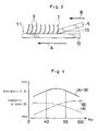
- FIG. 4 shows the relationships of the hardness (Vickers hardness) of the heat sink blank with the machinability of the blank (ease of cutting of the fin-forming portion) and with the properties of burrs produced.
- FIG. 4 indicates the machinability by a broken line (A), the properties of burrs by a chain line (B) and the sum of the two items by a solid line (A)+(B).
- FIG. 4 reveals that both the machinability and the properties of burrs produced are in a suitable range when the hardness Hv of the heat sink blank is in the range of 40 to 65.
- the blank can be easily cut to form the raised fins and drilled without producing burrs having such properties that they require removal work or are difficult to remove, whereby a rise in manufacturing cost can be suppressed.
- the extrudate for use in fabricating the heat sink of the invention preferably has an aluminum alloy composition comprising 0.2 to 0.6 wt. % of Si, 0.45 to 0.9 wt. % of Mg, and the balance A1 and inevitable impurities.
- the extrudate fails to have sufficient strength as the material, whereas if the Si content is over 0.6 wt. %, with the Mg content in excess of 0.9 wt. %, reduced productivity will result due to an increased load involved in extrusion. Further if in an amount of more than 0.9 wt. %, Mg forms a solid solution in aluminum, causing the distortion of the lattice structure of aluminum and impeding the passage of free electrons to result in lower thermal conductivity.
- the present invention also provides a method of fabricating the heat sink described above which method is characterized in that a fin-forming portion of a heat sink blank comprising an aluminum or aluminum alloy extrudate is cut in the same direction as the direction of extrusion of the extrudate to a raised form to thereby make a plurality of fins.
- FIGS. 1 to 3 show an embodiment of the present invention.
- the heat sink 1 comprises a base plate 2, and a plurality of parallel fins 3 formed on the upper surface of the base plate 2 except the peripheral portion thereof.
- Each fin 3 is in the form of a circular-arc plate elongated transversely of the base plate 2 and slightly bulging rearward in cross section.
- the fin 3 has two slits 31 extending vertically from its upper edge as if dividing the fin into three portions as arranged transversely of the base plate 2.
- a bolt hole 4 is formed in each of the four corners of the base plate 2 for inserting a bolt therethrough to attach the heat sink 1 to an electronic component.
- the blank 11 comprises a base plate portion 12, and a fin-forming portion 13 to be cut and provided on the upper side of the base plate portion 12.
- the fin-forming portion 13 has a slightly smaller width than the base plate portion 12 and two grooves 131 spaced apart by a predetermined distance and extending longitudinally of the base plate portion 12. These grooves 131 serve to form the slits 31 in the fins 3 to be obtained.
- the grooves 131 also serve to hold therein the cutting oil to be supplied when the fin-forming portion 13 is cut to a raised form as will be described below, whereby the portion 13 can be cut smoothly.
- the heat sink blank 11 is made of an aluminum alloy extrudate having a Vickers hardness Hv of 50 and comprising 0.6 wt. % of Si, 0.5 wt. % of Mg, and the balance A1 and inevitable impurities.
- the hardness was adjusted by aging the extrudate (at 230° C for 5 hours) after the extrusion.
- the arrow A shown in FIG. 2 indicates the direction of extrusion.
- the fin-forming portion 13 of the blank 11 is then cut to a raised form by using a cutting tool 5 or the like as shown in FIG. 3, whereby the fins 3 are formed.
- the portion 13 is cut in the same direction B as the direction of extrusion A.
- the fins 3 can be formed by this step very smoothly with high precision because the heat sink blank 11 is made of an aluminum alloy extrudate having the foregoing hardness and composition and also because the fin-forming portion 13 is cut toward the same direction B as the extrusion direction A.
- the base plate portion 12 of the blank 11 is drilled at its four corners as by a drill or press machine to form the bolt holes 4 (see FIG. 1).
- the inner peripheries of the base plate portion 12 which define the bolt holes 4 thus formed are free from burrs having such properties that they require deburring work or are difficult to remove since the aluminum alloy extrudate providing the blank 11 was adjusted to the aforementioned hardness.
Landscapes
- Engineering & Computer Science (AREA)
- Mechanical Engineering (AREA)
- Cooling Or The Like Of Semiconductors Or Solid State Devices (AREA)
- Extrusion Of Metal (AREA)
- Crystals, And After-Treatments Of Crystals (AREA)
- Manufacturing Of Magnetic Record Carriers (AREA)
Abstract
Description
Claims (3)
- A heat sink having a plurality of fins and fabricated from a blank comprising a base plate portion, and a fin-forming portion to be cut and provided on at least one side of the base plate portion by cutting the fin-forming portion to a raised form to make the fins, the heat sink being characterized in that the heat sink blank comprises an aluminum or aluminum alloy extrudate having a Vickers hardness of 40 to 65.
- A heat sink according to claim 1 which is characterized in that the extrudate has an aluminum alloy composition comprising 0.2 to 0.6 wt. % of Si, 0.45 to 0.9 wt. % of Mg, and the balance A1 and inevitable impurities.
- A method of fabricating a heat sink according to claim 1 or 2 characterized in that a fin-forming portion of a heat sink blank comprising an aluminum or aluminum alloy extrudate is cut in the same direction as the direction of extrusion of the extrudate to a raised form to thereby form a plurality of fins.
Applications Claiming Priority (2)
| Application Number | Priority Date | Filing Date | Title |
|---|---|---|---|
| JP33598099A JP4355412B2 (en) | 1999-11-26 | 1999-11-26 | Heat sink and manufacturing method thereof |
| JP33598099 | 1999-11-26 |
Publications (3)
| Publication Number | Publication Date |
|---|---|
| EP1104015A2 true EP1104015A2 (en) | 2001-05-30 |
| EP1104015A3 EP1104015A3 (en) | 2002-06-12 |
| EP1104015B1 EP1104015B1 (en) | 2004-12-15 |
Family
ID=18294460
Family Applications (1)
| Application Number | Title | Priority Date | Filing Date |
|---|---|---|---|
| EP00123612A Expired - Lifetime EP1104015B1 (en) | 1999-11-26 | 2000-10-28 | Method of fabricating a heat sink |
Country Status (9)
| Country | Link |
|---|---|
| US (1) | US6341651B1 (en) |
| EP (1) | EP1104015B1 (en) |
| JP (1) | JP4355412B2 (en) |
| KR (1) | KR100729584B1 (en) |
| CN (1) | CN1181539C (en) |
| AT (1) | ATE285120T1 (en) |
| CA (1) | CA2325799C (en) |
| DE (1) | DE60016703T2 (en) |
| TW (1) | TW473963B (en) |
Cited By (4)
| Publication number | Priority date | Publication date | Assignee | Title |
|---|---|---|---|---|
| EP1376677A3 (en) * | 2002-06-17 | 2006-03-01 | The Bergquist Company | Finned heat sinks |
| EP1450401B1 (en) * | 2001-11-29 | 2011-04-06 | Denki Kagaku Kogyo Kabushiki Kaisha | Module comprising a ceramic circuit board |
| WO2013095731A3 (en) * | 2011-12-20 | 2013-08-15 | Unison Industries, Llc | Method for forming a heat exchanger and portions thereof |
| US10865975B2 (en) | 2015-08-04 | 2020-12-15 | Signify Holding B.V. | Heat sink lighting device and method for manufacturing a heat sink |
Families Citing this family (30)
| Publication number | Priority date | Publication date | Assignee | Title |
|---|---|---|---|---|
| MY126022A (en) * | 2001-06-15 | 2006-09-29 | Wong Chee Tieng | Heat sink |
| CN100425110C (en) * | 2003-02-10 | 2008-10-08 | 聚亨企业股份有限公司 | Machining method and cutting tool for plane-fin radiator |
| US20040200608A1 (en) * | 2003-04-11 | 2004-10-14 | Baldassarre Gregg J. | Plate fins with vanes for redirecting airflow |
| JP4793838B2 (en) * | 2004-01-28 | 2011-10-12 | 中村製作所株式会社 | Manufacturing method of radiator |
| TW200536463A (en) * | 2004-04-20 | 2005-11-01 | Via Tech Inc | A dissipating device and manufacturing method thereof |
| JP4857017B2 (en) * | 2006-04-27 | 2012-01-18 | 日立オートモティブシステムズ株式会社 | Power converter |
| JP5118389B2 (en) * | 2007-05-26 | 2013-01-16 | 中村製作所株式会社 | Method for forming recess in workpiece |
| JP4888721B2 (en) | 2007-07-24 | 2012-02-29 | 中村製作所株式会社 | Manufacturing method of radiator having plate-like fins |
| KR101424136B1 (en) * | 2007-09-06 | 2014-08-04 | 삼성전자주식회사 | Heat exchanger for electronic parts having heat-generating fin |
| CN102357786B (en) * | 2011-09-15 | 2013-03-27 | 天津锐新昌轻合金股份有限公司 | Compensation method of modular radiator manufacturing process |
| US8938880B2 (en) * | 2012-02-20 | 2015-01-27 | Wolverine Tube, Inc. | Method of manufacturing an integrated cold plate for electronics |
| CN102861950A (en) * | 2012-09-21 | 2013-01-09 | 惠州智科实业有限公司 | Radiator cutting processing equipment |
| TWI566865B (en) * | 2014-01-10 | 2017-01-21 | 技嘉科技股份有限公司 | Heat sink and method of making the same |
| CN103781336B (en) * | 2014-01-10 | 2017-04-12 | 技嘉科技股份有限公司 | Radiator and method of manufacturing the same |
| KR101576959B1 (en) * | 2014-04-29 | 2015-12-11 | 송수동 | Heatsink for LED lighting lamp and manufacturing method thereof |
| EP3176273B1 (en) | 2014-07-30 | 2018-12-19 | UACJ Corporation | Aluminium alloy brazing sheet |
| JP6186455B2 (en) * | 2016-01-14 | 2017-08-23 | 株式会社Uacj | Heat exchanger and manufacturing method thereof |
| JP6758647B2 (en) * | 2017-01-17 | 2020-09-23 | 中村製作所株式会社 | Heat dissipation fin forming device |
| JP6916715B2 (en) | 2017-11-08 | 2021-08-11 | 株式会社Uacj | Brazing sheet and its manufacturing method |
| CN108705128A (en) * | 2018-06-20 | 2018-10-26 | 江苏英杰电子器件有限公司 | Cutting mechanism for machine case radiator processing equipment |
| US11571769B2 (en) | 2018-09-11 | 2023-02-07 | Uacj Corporation | Method of manufacturing a brazing sheet |
| KR102228431B1 (en) * | 2019-04-16 | 2021-03-16 | 부경대학교 산학협력단 | Method for manufacturing aluminum-based clad heat sink and aluminum-based clad heat sink manufactured thereby |
| JP7343166B2 (en) | 2019-11-13 | 2023-09-12 | ナカムラマジック株式会社 | Heat sink manufacturing method and heat sink |
| JP7591872B2 (en) | 2020-04-08 | 2024-11-29 | 株式会社Uacj | Manufacturing method of brazing sheet |
| CN111774821B (en) * | 2020-08-01 | 2024-08-13 | 石家庄长兴基业铁路配件有限公司 | An automatic production line for double-sided finning of aluminum profiles |
| KR102377051B1 (en) * | 2021-12-13 | 2022-03-21 | 주식회사 히트솔 | Heat sink manufacturing method and system |
| US12477695B2 (en) * | 2023-02-02 | 2025-11-18 | Amulaire Thermal Technology, Inc. | Two-phase immersion-cooling heat-dissipation structure having skived fins |
| JP2024140660A (en) | 2023-03-28 | 2024-10-10 | 住友精密工業株式会社 | Heat exchanger manufacturing method |
| CN118404343A (en) * | 2024-05-07 | 2024-07-30 | 易能数字能源技术(浙江)有限公司 | Processing device and method for skived-tooth radiator |
| KR102808313B1 (en) * | 2024-07-10 | 2025-05-20 | 주식회사 히트솔 | Heat dissipation busbar for circuit breakers and its manufacturing method |
Family Cites Families (13)
| Publication number | Priority date | Publication date | Assignee | Title |
|---|---|---|---|---|
| US385283A (en) * | 1888-06-26 | Convertible drain-cleaner | ||
| US3722073A (en) * | 1971-10-01 | 1973-03-27 | Int Nickel Co | Production of products directly from nickel cathodes |
| FR2185946A5 (en) * | 1972-05-23 | 1974-01-04 | Chausson Usines Sa | |
| JPS5461015A (en) * | 1977-10-25 | 1979-05-17 | Kobe Steel Ltd | Manufacture of aluminum-soldered fin heat exchanger |
| US4369838A (en) * | 1980-05-27 | 1983-01-25 | Aluminum Kabushiki Kaisha Showa | Device for releasing heat |
| DE3518310A1 (en) * | 1985-05-22 | 1986-11-27 | Aluminium-Walzwerke Singen Gmbh, 7700 Singen | REFRIGERATOR BODY FOR SEMICONDUCTOR COMPONENTS AND METHOD FOR THE PRODUCTION THEREOF |
| JPS62203630A (en) * | 1986-02-28 | 1987-09-08 | Showa Alum Corp | Production of radiator |
| EP0491088A1 (en) * | 1990-12-17 | 1992-06-24 | Hirose Manufacturing Company Limited | Rotary hook for sewing machines |
| US5260142A (en) * | 1990-12-28 | 1993-11-09 | Honda Giken Kogyo Kabushiki Kaisha | Corrosion-resistant clad material made of aluminum alloys |
| DE4200489C2 (en) * | 1991-01-19 | 1995-09-28 | Hitachi Metals Ltd | Two-part oil ring and process for its manufacture |
| JPH06232300A (en) * | 1993-02-03 | 1994-08-19 | Showa Alum Corp | Radiator |
| WO1996003748A1 (en) * | 1994-07-27 | 1996-02-08 | Minnesota Mining And Manufacturing Company | Tape cartridge base plate comprising a novel aluminum alloy |
| DE29602367U1 (en) * | 1995-03-24 | 1996-05-15 | Alusuisse-Lonza Services AG, Neuhausen am Rheinfall | Heat sink for semiconductor components or the like. |
-
1999
- 1999-11-26 JP JP33598099A patent/JP4355412B2/en not_active Expired - Fee Related
-
2000
- 2000-10-28 AT AT00123612T patent/ATE285120T1/en not_active IP Right Cessation
- 2000-10-28 EP EP00123612A patent/EP1104015B1/en not_active Expired - Lifetime
- 2000-10-28 DE DE60016703T patent/DE60016703T2/en not_active Expired - Fee Related
- 2000-11-14 CA CA2325799A patent/CA2325799C/en not_active Expired - Fee Related
- 2000-11-20 TW TW089124522A patent/TW473963B/en active
- 2000-11-20 KR KR1020000068904A patent/KR100729584B1/en not_active Expired - Fee Related
- 2000-11-20 US US09/715,095 patent/US6341651B1/en not_active Expired - Fee Related
- 2000-11-24 CN CNB00128326XA patent/CN1181539C/en not_active Expired - Lifetime
Cited By (5)
| Publication number | Priority date | Publication date | Assignee | Title |
|---|---|---|---|---|
| EP1450401B1 (en) * | 2001-11-29 | 2011-04-06 | Denki Kagaku Kogyo Kabushiki Kaisha | Module comprising a ceramic circuit board |
| EP1376677A3 (en) * | 2002-06-17 | 2006-03-01 | The Bergquist Company | Finned heat sinks |
| WO2013095731A3 (en) * | 2011-12-20 | 2013-08-15 | Unison Industries, Llc | Method for forming a heat exchanger and portions thereof |
| US9238284B2 (en) | 2011-12-20 | 2016-01-19 | Unison Industries, Llc | Methods for forming a heat exchanger and portions thereof |
| US10865975B2 (en) | 2015-08-04 | 2020-12-15 | Signify Holding B.V. | Heat sink lighting device and method for manufacturing a heat sink |
Also Published As
| Publication number | Publication date |
|---|---|
| EP1104015A3 (en) | 2002-06-12 |
| DE60016703T2 (en) | 2005-12-08 |
| CA2325799C (en) | 2011-09-20 |
| CN1298205A (en) | 2001-06-06 |
| TW473963B (en) | 2002-01-21 |
| EP1104015B1 (en) | 2004-12-15 |
| US6341651B1 (en) | 2002-01-29 |
| JP2001156224A (en) | 2001-06-08 |
| KR100729584B1 (en) | 2007-06-19 |
| DE60016703D1 (en) | 2005-01-20 |
| CN1181539C (en) | 2004-12-22 |
| JP4355412B2 (en) | 2009-11-04 |
| ATE285120T1 (en) | 2005-01-15 |
| KR20010070226A (en) | 2001-07-25 |
| CA2325799A1 (en) | 2001-05-26 |
Similar Documents
| Publication | Publication Date | Title |
|---|---|---|
| US6341651B1 (en) | Heat sink and method of fabricating same | |
| US6543521B1 (en) | Cooling element and cooling apparatus using the same | |
| US5771966A (en) | Folded conducting member heatsinks and method of making same | |
| US6339880B1 (en) | Process for manufacturing heat sink | |
| DE102007054856A1 (en) | Lighting device with a substrate plate and a heat sink | |
| US6516867B1 (en) | Heat sink manufacturing device and manufacturing method | |
| US6861293B2 (en) | Stacked fin heat sink and method of making | |
| JP5912282B2 (en) | Pin-shaped fin integrated heat sink and manufacturing method thereof | |
| JP2005142247A (en) | Radiator and manufacturing method therefor | |
| US20050229389A1 (en) | Heat sink fins processing installation | |
| AU2002353538A1 (en) | Extrusion tool, method for manufacturing shaped article with fins, and heat sink | |
| DE10251411B4 (en) | Device comprising an electronic circuit with at least one semiconductor module | |
| US20060090873A1 (en) | Method for manufacturing heat sink devices | |
| US20210043549A1 (en) | Clips for semiconductor packages | |
| JP7678958B2 (en) | Method for forming a heat sink | |
| JP2020167328A (en) | How to make a heat sink | |
| JPH0523360B2 (en) | ||
| JP2005057033A (en) | Pin fin-type heatsink and manufacturing method therefor | |
| US20070271787A1 (en) | Methods for manufacturing heat sink having relatively high aspects ratio thereof | |
| KR960006713B1 (en) | Method for manufacturing dam body for trimming lead frame and its dam body | |
| EP1554752B1 (en) | Device including a semiconductor module and a heatsink | |
| CN1571147A (en) | Heat sink fins and manufacturing method thereof | |
| JPH05235216A (en) | Method for manufacturing pin type heat radiation fin for semiconductor | |
| JP2006346815A (en) | Press die for aluminum shape material cutting and aluminum shape material cutting method | |
| JP2002110873A (en) | Fin fixed heat sink |
Legal Events
| Date | Code | Title | Description |
|---|---|---|---|
| PUAI | Public reference made under article 153(3) epc to a published international application that has entered the european phase |
Free format text: ORIGINAL CODE: 0009012 |
|
| AK | Designated contracting states |
Kind code of ref document: A2 Designated state(s): AT BE CH CY DE DK ES FI FR GB GR IE IT LI LU MC NL PT SE |
|
| AX | Request for extension of the european patent |
Free format text: AL;LT;LV;MK;RO;SI |
|
| RAP1 | Party data changed (applicant data changed or rights of an application transferred) |
Owner name: SHOWA DENKO KABUSHIKI KAISHA |
|
| PUAL | Search report despatched |
Free format text: ORIGINAL CODE: 0009013 |
|
| AK | Designated contracting states |
Kind code of ref document: A3 Designated state(s): AT BE CH CY DE DK ES FI FR GB GR IE IT LI LU MC NL PT SE |
|
| AX | Request for extension of the european patent |
Free format text: AL;LT;LV;MK;RO;SI |
|
| RIC1 | Information provided on ipc code assigned before grant |
Free format text: 7H 01L 21/48 A, 7H 01L 23/367 B, 7C 22F 1/05 B, 7C 22C 21/08 B, 7B 23P 15/26 B |
|
| 17P | Request for examination filed |
Effective date: 20021010 |
|
| AKX | Designation fees paid |
Designated state(s): AT BE CH CY DE DK ES FI FR GB GR IE IT LI LU MC NL PT SE |
|
| 17Q | First examination report despatched |
Effective date: 20030217 |
|
| GRAP | Despatch of communication of intention to grant a patent |
Free format text: ORIGINAL CODE: EPIDOSNIGR1 |
|
| RTI1 | Title (correction) |
Free format text: METHOD OF FABRICATING A HEAT SINK |
|
| GRAS | Grant fee paid |
Free format text: ORIGINAL CODE: EPIDOSNIGR3 |
|
| GRAA | (expected) grant |
Free format text: ORIGINAL CODE: 0009210 |
|
| AK | Designated contracting states |
Kind code of ref document: B1 Designated state(s): AT BE CH CY DE DK ES FI FR GB GR IE IT LI LU MC NL PT SE |
|
| PG25 | Lapsed in a contracting state [announced via postgrant information from national office to epo] |
Ref country code: IT Free format text: LAPSE BECAUSE OF FAILURE TO SUBMIT A TRANSLATION OF THE DESCRIPTION OR TO PAY THE FEE WITHIN THE PRESCRIBED TIME-LIMIT;WARNING: LAPSES OF ITALIAN PATENTS WITH EFFECTIVE DATE BEFORE 2007 MAY HAVE OCCURRED AT ANY TIME BEFORE 2007. THE CORRECT EFFECTIVE DATE MAY BE DIFFERENT FROM THE ONE RECORDED. Effective date: 20041215 Ref country code: AT Free format text: LAPSE BECAUSE OF FAILURE TO SUBMIT A TRANSLATION OF THE DESCRIPTION OR TO PAY THE FEE WITHIN THE PRESCRIBED TIME-LIMIT Effective date: 20041215 Ref country code: BE Free format text: LAPSE BECAUSE OF FAILURE TO SUBMIT A TRANSLATION OF THE DESCRIPTION OR TO PAY THE FEE WITHIN THE PRESCRIBED TIME-LIMIT Effective date: 20041215 Ref country code: LI Free format text: LAPSE BECAUSE OF FAILURE TO SUBMIT A TRANSLATION OF THE DESCRIPTION OR TO PAY THE FEE WITHIN THE PRESCRIBED TIME-LIMIT Effective date: 20041215 Ref country code: NL Free format text: LAPSE BECAUSE OF FAILURE TO SUBMIT A TRANSLATION OF THE DESCRIPTION OR TO PAY THE FEE WITHIN THE PRESCRIBED TIME-LIMIT Effective date: 20041215 Ref country code: CH Free format text: LAPSE BECAUSE OF FAILURE TO SUBMIT A TRANSLATION OF THE DESCRIPTION OR TO PAY THE FEE WITHIN THE PRESCRIBED TIME-LIMIT Effective date: 20041215 |
|
| REG | Reference to a national code |
Ref country code: CH Ref legal event code: EP Ref country code: GB Ref legal event code: FG4D |
|
| REG | Reference to a national code |
Ref country code: IE Ref legal event code: FG4D |
|
| REF | Corresponds to: |
Ref document number: 60016703 Country of ref document: DE Date of ref document: 20050120 Kind code of ref document: P |
|
| PG25 | Lapsed in a contracting state [announced via postgrant information from national office to epo] |
Ref country code: DK Free format text: LAPSE BECAUSE OF FAILURE TO SUBMIT A TRANSLATION OF THE DESCRIPTION OR TO PAY THE FEE WITHIN THE PRESCRIBED TIME-LIMIT Effective date: 20050315 Ref country code: GR Free format text: LAPSE BECAUSE OF FAILURE TO SUBMIT A TRANSLATION OF THE DESCRIPTION OR TO PAY THE FEE WITHIN THE PRESCRIBED TIME-LIMIT Effective date: 20050315 |
|
| PG25 | Lapsed in a contracting state [announced via postgrant information from national office to epo] |
Ref country code: ES Free format text: LAPSE BECAUSE OF FAILURE TO SUBMIT A TRANSLATION OF THE DESCRIPTION OR TO PAY THE FEE WITHIN THE PRESCRIBED TIME-LIMIT Effective date: 20050326 |
|
| REG | Reference to a national code |
Ref country code: SE Ref legal event code: TRGR |
|
| NLV1 | Nl: lapsed or annulled due to failure to fulfill the requirements of art. 29p and 29m of the patents act | ||
| REG | Reference to a national code |
Ref country code: CH Ref legal event code: PL |
|
| ET | Fr: translation filed | ||
| PLBE | No opposition filed within time limit |
Free format text: ORIGINAL CODE: 0009261 |
|
| STAA | Information on the status of an ep patent application or granted ep patent |
Free format text: STATUS: NO OPPOSITION FILED WITHIN TIME LIMIT |
|
| PG25 | Lapsed in a contracting state [announced via postgrant information from national office to epo] |
Ref country code: CY Free format text: LAPSE BECAUSE OF FAILURE TO SUBMIT A TRANSLATION OF THE DESCRIPTION OR TO PAY THE FEE WITHIN THE PRESCRIBED TIME-LIMIT Effective date: 20051028 Ref country code: IE Free format text: LAPSE BECAUSE OF NON-PAYMENT OF DUE FEES Effective date: 20051028 |
|
| PG25 | Lapsed in a contracting state [announced via postgrant information from national office to epo] |
Ref country code: LU Free format text: LAPSE BECAUSE OF NON-PAYMENT OF DUE FEES Effective date: 20051031 Ref country code: MC Free format text: LAPSE BECAUSE OF NON-PAYMENT OF DUE FEES Effective date: 20051031 |
|
| 26N | No opposition filed |
Effective date: 20050916 |
|
| REG | Reference to a national code |
Ref country code: IE Ref legal event code: MM4A |
|
| PGFP | Annual fee paid to national office [announced via postgrant information from national office to epo] |
Ref country code: SE Payment date: 20061004 Year of fee payment: 7 |
|
| PGFP | Annual fee paid to national office [announced via postgrant information from national office to epo] |
Ref country code: FI Payment date: 20061012 Year of fee payment: 7 |
|
| PG25 | Lapsed in a contracting state [announced via postgrant information from national office to epo] |
Ref country code: PT Free format text: LAPSE BECAUSE OF NON-PAYMENT OF DUE FEES Effective date: 20050515 |
|
| PGFP | Annual fee paid to national office [announced via postgrant information from national office to epo] |
Ref country code: DE Payment date: 20071025 Year of fee payment: 8 |
|
| PGFP | Annual fee paid to national office [announced via postgrant information from national office to epo] |
Ref country code: GB Payment date: 20071024 Year of fee payment: 8 |
|
| EUG | Se: european patent has lapsed | ||
| PG25 | Lapsed in a contracting state [announced via postgrant information from national office to epo] |
Ref country code: FI Free format text: LAPSE BECAUSE OF NON-PAYMENT OF DUE FEES Effective date: 20071028 |
|
| REG | Reference to a national code |
Ref country code: FR Ref legal event code: ST Effective date: 20080630 |
|
| PG25 | Lapsed in a contracting state [announced via postgrant information from national office to epo] |
Ref country code: SE Free format text: LAPSE BECAUSE OF NON-PAYMENT OF DUE FEES Effective date: 20071029 |
|
| PGFP | Annual fee paid to national office [announced via postgrant information from national office to epo] |
Ref country code: FR Payment date: 20061010 Year of fee payment: 7 |
|
| PG25 | Lapsed in a contracting state [announced via postgrant information from national office to epo] |
Ref country code: FR Free format text: LAPSE BECAUSE OF NON-PAYMENT OF DUE FEES Effective date: 20071031 |
|
| GBPC | Gb: european patent ceased through non-payment of renewal fee |
Effective date: 20081028 |
|
| PG25 | Lapsed in a contracting state [announced via postgrant information from national office to epo] |
Ref country code: DE Free format text: LAPSE BECAUSE OF NON-PAYMENT OF DUE FEES Effective date: 20090501 |
|
| PG25 | Lapsed in a contracting state [announced via postgrant information from national office to epo] |
Ref country code: GB Free format text: LAPSE BECAUSE OF NON-PAYMENT OF DUE FEES Effective date: 20081028 |