EP1103961A2 - Cartridge-contained recording medium - Google Patents
Cartridge-contained recording medium Download PDFInfo
- Publication number
- EP1103961A2 EP1103961A2 EP00125578A EP00125578A EP1103961A2 EP 1103961 A2 EP1103961 A2 EP 1103961A2 EP 00125578 A EP00125578 A EP 00125578A EP 00125578 A EP00125578 A EP 00125578A EP 1103961 A2 EP1103961 A2 EP 1103961A2
- Authority
- EP
- European Patent Office
- Prior art keywords
- layer
- thickness
- magneto
- cartridge
- Prior art date
- Legal status (The legal status is an assumption and is not a legal conclusion. Google has not performed a legal analysis and makes no representation as to the accuracy of the status listed.)
- Withdrawn
Links
Images

Classifications
-
- G—PHYSICS
- G11—INFORMATION STORAGE
- G11B—INFORMATION STORAGE BASED ON RELATIVE MOVEMENT BETWEEN RECORD CARRIER AND TRANSDUCER
- G11B23/00—Record carriers not specific to the method of recording or reproducing; Accessories, e.g. containers, specially adapted for co-operation with the recording or reproducing apparatus ; Intermediate mediums; Apparatus or processes specially adapted for their manufacture
- G11B23/38—Visual features other than those contained in record tracks or represented by sprocket holes the visual signals being auxiliary signals
- G11B23/40—Identifying or analogous means applied to or incorporated in the record carrier and not intended for visual display simultaneously with the playing-back of the record carrier, e.g. label, leader, photograph
-
- G—PHYSICS
- G11—INFORMATION STORAGE
- G11B—INFORMATION STORAGE BASED ON RELATIVE MOVEMENT BETWEEN RECORD CARRIER AND TRANSDUCER
- G11B11/00—Recording on or reproducing from the same record carrier wherein for these two operations the methods are covered by different main groups of groups G11B3/00 - G11B7/00 or by different subgroups of group G11B9/00; Record carriers therefor
-
- G—PHYSICS
- G11—INFORMATION STORAGE
- G11B—INFORMATION STORAGE BASED ON RELATIVE MOVEMENT BETWEEN RECORD CARRIER AND TRANSDUCER
- G11B11/00—Recording on or reproducing from the same record carrier wherein for these two operations the methods are covered by different main groups of groups G11B3/00 - G11B7/00 or by different subgroups of group G11B9/00; Record carriers therefor
- G11B11/10—Recording on or reproducing from the same record carrier wherein for these two operations the methods are covered by different main groups of groups G11B3/00 - G11B7/00 or by different subgroups of group G11B9/00; Record carriers therefor using recording by magnetic means or other means for magnetisation or demagnetisation of a record carrier, e.g. light induced spin magnetisation; Demagnetisation by thermal or stress means in the presence or not of an orienting magnetic field
- G11B11/105—Recording on or reproducing from the same record carrier wherein for these two operations the methods are covered by different main groups of groups G11B3/00 - G11B7/00 or by different subgroups of group G11B9/00; Record carriers therefor using recording by magnetic means or other means for magnetisation or demagnetisation of a record carrier, e.g. light induced spin magnetisation; Demagnetisation by thermal or stress means in the presence or not of an orienting magnetic field using a beam of light or a magnetic field for recording by change of magnetisation and a beam of light for reproducing, i.e. magneto-optical, e.g. light-induced thermomagnetic recording, spin magnetisation recording, Kerr or Faraday effect reproducing
- G11B11/10582—Record carriers characterised by the selection of the material or by the structure or form
- G11B11/10584—Record carriers characterised by the selection of the material or by the structure or form characterised by the form, e.g. comprising mechanical protection elements
-
- G—PHYSICS
- G11—INFORMATION STORAGE
- G11B—INFORMATION STORAGE BASED ON RELATIVE MOVEMENT BETWEEN RECORD CARRIER AND TRANSDUCER
- G11B11/00—Recording on or reproducing from the same record carrier wherein for these two operations the methods are covered by different main groups of groups G11B3/00 - G11B7/00 or by different subgroups of group G11B9/00; Record carriers therefor
- G11B11/10—Recording on or reproducing from the same record carrier wherein for these two operations the methods are covered by different main groups of groups G11B3/00 - G11B7/00 or by different subgroups of group G11B9/00; Record carriers therefor using recording by magnetic means or other means for magnetisation or demagnetisation of a record carrier, e.g. light induced spin magnetisation; Demagnetisation by thermal or stress means in the presence or not of an orienting magnetic field
- G11B11/105—Recording on or reproducing from the same record carrier wherein for these two operations the methods are covered by different main groups of groups G11B3/00 - G11B7/00 or by different subgroups of group G11B9/00; Record carriers therefor using recording by magnetic means or other means for magnetisation or demagnetisation of a record carrier, e.g. light induced spin magnetisation; Demagnetisation by thermal or stress means in the presence or not of an orienting magnetic field using a beam of light or a magnetic field for recording by change of magnetisation and a beam of light for reproducing, i.e. magneto-optical, e.g. light-induced thermomagnetic recording, spin magnetisation recording, Kerr or Faraday effect reproducing
- G11B11/10582—Record carriers characterised by the selection of the material or by the structure or form
- G11B11/10586—Record carriers characterised by the selection of the material or by the structure or form characterised by the selection of the material
-
- G—PHYSICS
- G11—INFORMATION STORAGE
- G11B—INFORMATION STORAGE BASED ON RELATIVE MOVEMENT BETWEEN RECORD CARRIER AND TRANSDUCER
- G11B7/00—Recording or reproducing by optical means, e.g. recording using a thermal beam of optical radiation by modifying optical properties or the physical structure, reproducing using an optical beam at lower power by sensing optical properties; Record carriers therefor
- G11B7/24—Record carriers characterised by shape, structure or physical properties, or by the selection of the material
-
- Y—GENERAL TAGGING OF NEW TECHNOLOGICAL DEVELOPMENTS; GENERAL TAGGING OF CROSS-SECTIONAL TECHNOLOGIES SPANNING OVER SEVERAL SECTIONS OF THE IPC; TECHNICAL SUBJECTS COVERED BY FORMER USPC CROSS-REFERENCE ART COLLECTIONS [XRACs] AND DIGESTS
- Y10—TECHNICAL SUBJECTS COVERED BY FORMER USPC
- Y10S—TECHNICAL SUBJECTS COVERED BY FORMER USPC CROSS-REFERENCE ART COLLECTIONS [XRACs] AND DIGESTS
- Y10S428/00—Stock material or miscellaneous articles
- Y10S428/90—Magnetic feature
-
- Y—GENERAL TAGGING OF NEW TECHNOLOGICAL DEVELOPMENTS; GENERAL TAGGING OF CROSS-SECTIONAL TECHNOLOGIES SPANNING OVER SEVERAL SECTIONS OF THE IPC; TECHNICAL SUBJECTS COVERED BY FORMER USPC CROSS-REFERENCE ART COLLECTIONS [XRACs] AND DIGESTS
- Y10—TECHNICAL SUBJECTS COVERED BY FORMER USPC
- Y10T—TECHNICAL SUBJECTS COVERED BY FORMER US CLASSIFICATION
- Y10T428/00—Stock material or miscellaneous articles
- Y10T428/21—Circular sheet or circular blank
- Y10T428/211—Gear
Definitions
- This invention relates to a cartridge-contained recording medium especially suitable for application to a disc contained in a cartridge and having a printed layer on at least one surface.
- Magneto-optical recording is made by irradiating a laser beam onto a signal recording layer and simultaneously applying a magnetic field from a magnetic head in a record/reproduce apparatus.
- MD Magneto-optical recording medium used for such magneto-optical recording.
- Magneto-optical recording mediums typically have a multi-layered structure sequentially stacking a first dielectric layer, signal recording layer, second dielectric layer and light reflecting layer on a substrate. Further formed on the light reflecting layer is a protective films.
- Magneto-optical recording mediums with colored protective films have more factors that appeal to one's eyes than conventionally used magneto-optical recording mediums. Therefore, they can meet user's requirements more easily. However, it was still difficult to distinguish products in accordance with increased demands from users for distinctiveness and progressively variable users' tastes.
- a cartridge-contained recording medium in which a recording medium is contained in a cartridge, characterized in a first dielectric layer, a signal recording layer, a second dielectric layer, a light reflecting layer, a first protective layer, a print layer and a second protective layer are sequentially stacked on a base body of the recording medium; and the second protective layer has a thickness not smaller than that of the print layer.
- thickness of the second protective film is preferably larger than that of the print layer.
- thickness of the first protective film is typically not smaller than 2 ⁇ m.
- thickness of the second protective film is typically not smaller than 5 ⁇ m.
- thickness of the second protective layer formed on the print layer is typically not beyond the range from 1.1 times to 2.0 times of the thickness of the print layer, and preferably not beyond the range from 1.2 times to 1.5 times of the thickness of the print layer.
- total thickness of the first protective layer, print layer and second protective layer is typically from 12 ⁇ m to 20 ⁇ m.
- protective layer is typically from 12 ⁇ m, to 20 ⁇ m.
- thickness of the print layer is typically from 3 ⁇ m to 8 ⁇ m, and preferably from 5 ⁇ m to 6 ⁇ m.
- thickness of the print layer is typically from 1 ⁇ m to 3 ⁇ m.
- a white-colored layer is typically provided as a base layer of the print layer.
- the protective film formed on the print layer has a thickness not smaller than that of the print layer, possible unevenness of the print layer can be sufficiently masked by the second protective layer, and the recoding medium can be improved in smoothness of its surface.
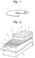
- Fig. 1 is a perspective view of a magneto-optical disc according to the first embodiment of the invention
- Fig. 2 is a perspective, cross-sectional view of a portion of the magneto-optical disc, taken along the II-II line of Fig. 1;
- Fig. 3 is an exploded, perspective view that shows a cartridge and a magneto-optical disc contained in the cartridge according to the first embodiment of the invention.
- FIG. 1 a cross-sectional structure taken along the II-II line of Fig. 1 is shown in Fig. 2.
- the magneto-optical disc 1 As shown in Fig. 1, the magneto-optical disc 1 according to the first embodiment has the form of a disc.
- the magneto-optical disc 1 is made by sequentially Stacking a first dielectric layer 3, signal recording layer 4, second dielectric layer 5, light reflecting layer 6, first protective layer 7, print layer 8 and second protective layer 9 on a substrate 2.
- the substrate 2 is a disc-shaped member made of a hard material transparent to laser beams.
- the hard material forming the substrate 2 are resins and glass. More specifically, polycarbonate resin, acrylic resin or polyolefin resin, for example, is used as a resin material, and quartz glass, for example, is used as a glass material. In the embodiment shown here, the substrate 2 is made of polycarbonate resin, for example.
- the substrate has formed a plurality of grooves 2a.
- the grooves are concentric and parallel with each other on the surface of the substrate 2, and are configured to meander over a fine width with a constant period in the radial direction of the substrate 2.
- the first dielectric layer 3 is made of a material which is transparent to laser beams projected upon recording or reproduction of signals but does not allow oxygen (O 2 ) and water molecules (H 2 O) to pass through. More specifically, the first dielectric layer 3 is preferably, made of a material not containing oxygen, and it is therefore made or silicon nitride (Si 3 N 4 , SiN) or aluminum nitride (AlN) . In the embodiment shown here, the first dielectric layer 3 is made of SiN, for example. The first dielectric layer 3 may be made by using a film-making technique such as sputtering, for example.
- the magneto-optical recording layer of the signal recording layer 4 is made of a material which is inverted in magnetization in an external magnetic field when its coercive force decreases by an increase of the temperature to above a Curie temperature and has magneto-optical properties such as Kerr effect and Faraday effect.
- the magneto-optical recording layer is made of an alloy of rare earth metals and transition metals, such as TbFeCo, TbFeCoCr, or GdFeCo, for example.
- the signal recording layer 4 is made of TbFeCoCr, for example.
- the second dielectric layer 5 is a thin film stacked on the signal recording layer 4, and it is made of any one of the materials usable as the first dielectric layer 3.
- the light reflecting layer 6, which is a thin film stacked on the second dielectric layer 5, is made of a material using one of non-magnetic metal elements or one of their compounds, independently, or combining them, such as gold (Au) or Al, for example.
- the light reflecting layer 6 is made of Al, for example.
- the light reflecting layer 6 functions to reflect laser beams sequentially passing through the signal recording layer 4 and the second dielectric layer 5.
- the light reflecting layer 6 also has a function as a heat sink for radiating heat generated in the signal recording layer 4 by laser beams projected toward the signal recording layer 4.
- the first protective layer 7 in form of a thin film stacked on the light reflecting layer 6 is made of an ultraviolet-setting resin, for example. Thickness of the first protective layer 7 is adjusted to be not smaller than 2 ⁇ m. In this particular embodiment, it is 2.5 ⁇ m, for example.
- the first protective layer 7 may be made by curing a material coated by spin coating using a spin coater, for example. The first protective layer 7 functions to prevent deterioration of the underlying light reflecting layer 6 and signal recording layer 4 by oxidation, and functions to prevent damages to the first dielectric layer 3, signal recording layer 4, second dielectric layer 5 and light reflecting layer 6 on the substrate.
- the first protective layer 7 it is possible to use one coated with or containing.
- the print layer 8 is made of an ultraviolet-setting resin ink (UV ink) hardened by irradiation of ultraviolet rays, for example. Thickness of the print layer 8 is determined typically in the range from 3 to 8 ⁇ m, preferably in the range from 5 to 6 ⁇ m. In the embodiment shown here, it is 5 ⁇ m, for example.
- Usable as a technique for making this print layer 8 is screen printing or offset printing. In addition to those, other printing techniques such as ink jet printing using water-color ink, for example, and electronic photography using fine-grain powder like a toner, for example, are also usable for making the print layer 8. These techniques make it possible to very delicate, high-fidelity printing, and contribute to remarkable improvement of the texture of the magneto-optical disc 1.
- the second protective layer 9 stacked on the print layer 8 is made of the same ultraviolet-setting resin as that of the first protective layer 7.
- thickness of the second protective layer 9 is determined to be not smaller than the thickness of the print layer 8.
- thickness of the second protective layer 9 is in the range from 1.1 time to 2.0 times of the thickness of the print layer 8, and more preferably in the range from 1.2 times to 1.5 times of the thickness of the print layer 8.
- thickness of the second protective layer 9 is determined to be not smaller than 5 ⁇ m, for example, to be 6 ⁇ m, as being 1.2 times the thickness of the print layer 8.
- Total thickness of the first protective layer 7, print layer 8 and second protective layer 9 should not be as large as making it difficult to obtain a test signal, namely, not larger than 20 ⁇ m or more preferably in the range from 12 to 20 ⁇ m, for example.
- total thickness of the first protective layer 7, print layer 8 and second protective layer 9 is 13.5 ⁇ m (2.5+5+6), for example, and individual thicknesses of the first protective layer, print layer 8 and second protective layer 9 are chosen under that condition.
- the magneto-optical disc 1 As shown in Fig. 3, the magneto-optical disc 1 according to the embodiment is contained in a housing (cartridge) 13 made by combining an upper shell 11 and a lower shell 12.
- the magneto-optical disc 1 can rotate inside the cartridge 13, and a metal plate 14 for the chucking purpose is provided at its center.
- a shutter 15 In a part of the cartridge 13, a shutter 15 is provided and configured to open and close at least upon reproducing and recording information with the magneto-optical disc 1.
- the cartridge 13 is configured to give external sight of at lest a part of printed information 16 like character information or design information the print information of the print layer 8 formed on one or both surfaces of the magneto-optical disc 1. That is, a part or all of the shell confronting at least one of surfaces of the magneto-optical disc 1 having formed the print layer 8 is made of colorless or colored transparent material such as plastic. More specifically, as shown in Fig. 3, a part of the upper shell 11 confronting the surface la of the magneto-optical disc 1 bearing the printed information 16, through which at least a part of the printed information 16 can be seen from the exterior of the cartridge 13, is made of a colorless or colored transparent material. This is also for lower shell 12.
- the magneto-optical disc 1 contained in the cartridge 13 having the above-explained configuration is supplied to a user as MD, for example.
- the magneto-optical disc 1 contained in the disc cartridge is configured to be removably inserted into a record/reproduce apparatus (not shown) including a magnetic head or optical head. Then, with this record/reproduce apparatus, the magneto-optical disc 1 can undergo recording and reproduction over a plurality of times.
- a laser beam of a predetermined output power is irradiated from an optical head onto a surface 2b of the disc-shaped substrate 2 opposite from the surface carrying the signal recording layer 4, and a magnetic field corresponding to the recording signal is applied from a recording magnetic head (not shown) onto the surface having the signal recording layer 4.
- the coercive force is decreased by increasing the temperature of the signal recording layer 4 of the magneto-optical disc 1 by the laser beam.
- a magnetic domain corresponding to the recording signal is domain corresponding to the recording signal is recorded on the signal recording layer 4 by the magnetic field applied from the recording magnetic head.
- a laser beam with an output power weaker than he laser light used for recording is irradiated onto the magneto-optical disc 1 from a pickup (not shown).
- This laser beam is reflected by the light reflecting layer 6 of the magneto-optical disc 1, reflecting the status of the record/reproduce layer 4.
- the reflected laser beam contains polarization due to a magneto-optical effect such as Kerr effect and Faraday effect. Then, polarization direction of the return beam is detected by the record/reproduce apparatus, and direction of the magnetic field in the magnetic domain recorded on the signal recording layer is detected. Through those operations, recording signals are reproduced.
- the magneto-optical disc 1 is configured to conduct recording/reproduction of signals on or from the signal recording layer 4 along the groove 2a. For this reason, recording tracks are formed along grooves 2a.
- the grooves 2a have periodically meandering forms. And, they are configured such that a record/reproduce apparatus can read the period of the meandering grooves 2a of the magneto-optical disc 1 during record/reproduce operation of magneto-optical disc 1 with a laser beam. Then, by reading the periodical meanders of the grooves 2a, the record/reproduce apparatus can maintain the rotating sped of the magneto-optical disc 1 in a normally stable condition.
- the grooves 2a are also used as a positional reference upon recording or reproducing signals on or from the signal recording layer 4 in the record/reproduce apparatus. That is, the grooves 2a have the function of indicating recording position (address) of a signal on the magneto-optical disc 1. Because of this function, by reading an address based on a groove 2a upon recording or reproduction of the magneto-optical disc 1, the record/reproduce apparatus can precisely fix the position for recording or reproduction in a short time.
- BLER Block Error Rate
- magneto-optical discs 1 Evaluation of magneto-optical discs 1 according to the embodiment is shown in Table 1, and evaluation of magneto-optical discs different in thicknesses from those according to the embodiment of the invention is shown in Table 2.
- a( ⁇ m) is the thickness of the second protective layer 9
- b( ⁇ m) is the thickness of the print layer 8
- c( ⁇ m) is the thickness of the first protective layer 7.
- Example 1 Example 2
- Example 3 Example 4
- Example 5 a( ⁇ m) 6 6 7.5 10 5 b(,um) 5 5 5 5 5 C( ⁇ m) 2.5 2.0 2.5 2.5 2.5 2.5 2.5 BLER (before warehousing) % 0.02 0.02 0.03 0.03 0.02 BLER (after warehousing) % 0.04 0.8 0.03 0.03 0.05 Frictional Force (mN) 3 3 3 6 printability ⁇ ⁇ ⁇ ⁇ ⁇ Comp.
- Example 1 Comp.
- Example 2 Comp.
- Example 3 a( ⁇ m) 6 3 4 b( ⁇ m) 5 5 5 c( ⁇ m) 1.5 2.5 2.5 BLER (before warehousing) % 0.02 0.02 0.02 BLER (after warehousing) % 4 5 4 Frictional Force (mN) 3 12 7 printability ⁇ ⁇ ⁇
- the magneto-optical disc 1 in the magneto-optical disc 1 contained in the cartridge 13, since the second protective layer 9 stacked on the print layer 8 has a thickness not smaller than the thickness of the print layer 8, the second protective layer 9 can effectively mask unevenness in level of the print layer 8. Therefore, good slidableness is ensured, and resistance to corrosion can be improved. Additionally, by stacking the first protective layer 7 to a thickness not less than 2 ⁇ m on the light reflecting layer 6, resistance to corrosion can be improved further. Therefore, the magneto-optical disc 1 ensures stable recording and reproduction while exhibiting sufficient resistance to corrosion and good slidableness, and makes it possible to give character information and design information by printing by using at least one surface of the magneto-optical disc 1.
- MD data MD-DATA
- MD data 2 MD-DATA II
- the print layer 8 may be formed to have a monochromatic print using a single color.
- thickness of the monochromatic print layer 8 is determined in the range from 1 to 3 ⁇ m.
- a white base film may be provided for the purpose of increasing the color visibility.
- first dielectric layer 3 and the second dielectric layer 5 of SiN may be made of any other appropriate material, such as zinc sulfide (ZnS), zirconium oxide (ZrO 2 ), yttrium oxide (Y 2 O 3 ), magnesium oxide (MgO), silicon oxide (SiO 2 ), magnesium fluoride (MgF 2 ), aluminum oxide (alumina: Al 2 O 3 ), aluminum silicide nitride oxide (AlSiNO), hafnium oxide (EfO 2 ) or lithium fluoride (LiF), for example.
- ZnS zinc sulfide
- ZrO 2 zirconium oxide
- Y 2 O 3 yttrium oxide
- magnesium oxide MgO
- silicon oxide SiO 2
- aluminum oxide alumina: Al 2 O 3
- AlSiNO aluminum silicide nitride oxide
- hafnium oxide EfO 2
- LiF lithium fluoride
- a cartridge-contained recording medium made by stacking a first protective layer, print layer and second protective layer sequentially from a side nearer to a base body of the recording medium, by determining the thickness of the second protective layer to be not smaller than the thickness of the print layer, it is possible to ensure a sufficient resistance to corrosion of the recording medium and a good slidableness thereof even when a print is applied on at least one surface of the recording medium.
Landscapes
- Optical Record Carriers And Manufacture Thereof (AREA)
Abstract
In a magneto-optical disc contained in a
cartridge, a first dielectric layer (3), signal
recording layer (4), second dielectric layer (5), and light
reflecting layer (6) are sequentially stacked on a
substrate (2) having formed grooves (2a), and a first
protective layer (7), print layer (8) using at least one
color and second protective layer (9) are sequentially
stacked on the light reflecting layer (6). Thickness
of the second protective layer (9) is not smaller than
that of the print layer (8), and thickness of the first
protective layer (7) is not smaller than 2 µm. Thus
the recording medium having the print layer on at
least one surface maintains a sufficient resistance
to corrosion and a good slidableness.
Description
- This invention relates to a cartridge-contained recording medium especially suitable for application to a disc contained in a cartridge and having a printed layer on at least one surface. Description of the Related Arts
- Magneto-optical recording is made by irradiating a laser beam onto a signal recording layer and simultaneously applying a magnetic field from a magnetic head in a record/reproduce apparatus. There is MD (Mini Disc), for example, as a magneto-optical recording medium used for such magneto-optical recording.
- Magneto-optical recording mediums typically have a multi-layered structure sequentially stacking a first dielectric layer, signal recording layer, second dielectric layer and light reflecting layer on a substrate. Further formed on the light reflecting layer is a protective films.
- Recently proposed was a magneto-optical recording medium with a colored protective film to conform to the consumer preference.
- Magneto-optical recording mediums with colored protective films have more factors that appeal to one's eyes than conventionally used magneto-optical recording mediums. Therefore, they can meet user's requirements more easily. However, it was still difficult to distinguish products in accordance with increased demands from users for distinctiveness and progressively variable users' tastes.
- As a method for meeting users' demands for distinctiveness and satisfying a variety of tastes, printing on disc planes was proposed.
- However, printing on disc planes caused corrosion of discs by ink. and degradation in accuracy of magnetic heads by deterioration of surface qualities derived from uneven printed planes.
- It is therefore an object of the invention to provide a cartridge-contained recording medium that has a sufficient resistance to corrosion even when a print is applied onto at least one surface of the recording medium and simultaneously has good slidableness.
- According to the invention, there is provided a cartridge-contained recording medium in which a recording medium is contained in a cartridge, characterized in a first dielectric layer, a signal recording layer, a second dielectric layer, a light reflecting layer, a first protective layer, a print layer and a second protective layer are sequentially stacked on a base body of the recording medium; and the second protective layer has a thickness not smaller than that of the print layer.
- In the present invention, for the purpose of improving the resistance to corrosion of the recording medium and obtain good slidableness, thickness of the second protective film is preferably larger than that of the print layer.
- In the present invention, for the purpose of ensuring a sufficient resistance to corrosion of the recording medium and forming a print layer on a good plane, thickness of the first protective film is typically not smaller than 2 µm.
- In the present invention, for the purpose of preventing damages to the surface of the recording medium, thickness of the second protective film is typically not smaller than 5 µm.
- In the present invention, for the purpose of ensuring the effect of sufficiently masking unevenness of the print layer and obtaining a good protective property and a good recording property, thickness of the second protective layer formed on the print layer is typically not beyond the range from 1.1 times to 2.0 times of the thickness of the print layer, and preferably not beyond the range from 1.2 times to 1.5 times of the thickness of the print layer.
- In the present invention, total thickness of the first protective layer, print layer and second protective layer is typically from 12 µm to 20 µm.
- protective layer is typically from 12 µm, to 20 µm. In the present invention, for the purpose of maintaining a print clean, if at lest two or more colors are used on the print layer, thickness of the print layer is typically from 3 µm to 8 µm, and preferably from 5 µm to 6 µm. Furthermore, in the present invention, if a single color is used on the print layer, thickness of the print layer is typically from 1 µm to 3 µm. In the present invention, for the purpose of improving visibility of printed colors, a white-colored layer is typically provided as a base layer of the print layer.
- According to the cartridge-contained recording medium having the above-summarized configuration according to the invention, since the protective film formed on the print layer has a thickness not smaller than that of the print layer, possible unevenness of the print layer can be sufficiently masked by the second protective layer, and the recoding medium can be improved in smoothness of its surface.
- The above, and other, objects, features and advantage of the present invention will become readily apparent from the following detailed description thereof which is to be read in connection with the accompanying drawings.
- Fig. 1 is a perspective view of a magneto-optical disc according to the first embodiment of the invention;
- Fig. 2 is a perspective, cross-sectional view of a portion of the magneto-optical disc, taken along the II-II line of Fig. 1; and
- Fig. 3 is an exploded, perspective view that shows a cartridge and a magneto-optical disc contained in the cartridge according to the first embodiment of the invention.
- Explained below is an embodiment of the invention with reference to the drawings. In all of the figures illustrating the embodiment shown below, the same or equivalent parts of elements are labeled with common reference numerals.
- First made is an explanation about a magneto-optical disc contained in a cartridge, according to the first embodiment of the invention. This magneto-optical disc according to the first embodiment is shown in Fig. 1, and a cross-sectional structure taken along the II-II line of Fig. 1 is shown in Fig. 2.
- As shown in Fig. 1, the magneto-
optical disc 1 according to the first embodiment has the form of a disc. - As shown in Fig. 2, the magneto-
optical disc 1 according to the first embodiment is made by sequentially Stacking a firstdielectric layer 3, signal recording layer 4, seconddielectric layer 5,light reflecting layer 6, firstprotective layer 7,print layer 8 and secondprotective layer 9 on a substrate 2. - The substrate 2 is a disc-shaped member made of a hard material transparent to laser beams. Usable as the hard material forming the substrate 2 are resins and glass. More specifically, polycarbonate resin, acrylic resin or polyolefin resin, for example, is used as a resin material, and quartz glass, for example, is used as a glass material. In the embodiment shown here, the substrate 2 is made of polycarbonate resin, for example.
- The substrate has formed a plurality of
grooves 2a. The grooves are concentric and parallel with each other on the surface of the substrate 2, and are configured to meander over a fine width with a constant period in the radial direction of the substrate 2. - The first
dielectric layer 3 is made of a material which is transparent to laser beams projected upon recording or reproduction of signals but does not allow oxygen (O2) and water molecules (H2O) to pass through. More specifically, the firstdielectric layer 3 is preferably, made of a material not containing oxygen, and it is therefore made or silicon nitride (Si3N4, SiN) or aluminum nitride (AlN) . In the embodiment shown here, the firstdielectric layer 3 is made of SiN, for example. The firstdielectric layer 3 may be made by using a film-making technique such as sputtering, for example. - The signal layer 4, which is a thin film stacked on the first
dielectric film 3, includes at least a magneto-optical recording layer. More specifically, used as the signal recording layer 4 is a single-layered or multi-layered magneto-optical recording layer or a multi-layered structure including a magneto-optical recording layer and a dielectric layer, which is proposed for CAD (center aperture detector) discs or MSR (Magnetically induced Super Resolution) discs. The magneto-optical recording layer of the signal recording layer 4 is made of a material which is inverted in magnetization in an external magnetic field when its coercive force decreases by an increase of the temperature to above a Curie temperature and has magneto-optical properties such as Kerr effect and Faraday effect. More specifically, the magneto-optical recording layer is made of an alloy of rare earth metals and transition metals, such as TbFeCo, TbFeCoCr, or GdFeCo, for example. In the embodiment shown here, the signal recording layer 4 is made of TbFeCoCr, for example. - The second
dielectric layer 5 is a thin film stacked on the signal recording layer 4, and it is made of any one of the materials usable as the firstdielectric layer 3. - The
light reflecting layer 6, which is a thin film stacked on the seconddielectric layer 5, is made of a material using one of non-magnetic metal elements or one of their compounds, independently, or combining them, such as gold (Au) or Al, for example. In the embodiment shown here, thelight reflecting layer 6 is made of Al, for example. Thelight reflecting layer 6 functions to reflect laser beams sequentially passing through the signal recording layer 4 and the seconddielectric layer 5. Thelight reflecting layer 6 also has a function as a heat sink for radiating heat generated in the signal recording layer 4 by laser beams projected toward the signal recording layer 4. - The first
protective layer 7 in form of a thin film stacked on thelight reflecting layer 6 is made of an ultraviolet-setting resin, for example. Thickness of the firstprotective layer 7 is adjusted to be not smaller than 2 µm. In this particular embodiment, it is 2.5 µm, for example. The firstprotective layer 7 may be made by curing a material coated by spin coating using a spin coater, for example. The firstprotective layer 7 functions to prevent deterioration of the underlyinglight reflecting layer 6 and signal recording layer 4 by oxidation, and functions to prevent damages to the firstdielectric layer 3, signal recording layer 4, seconddielectric layer 5 andlight reflecting layer 6 on the substrate. - As the first
protective layer 7, it is possible to use one coated with or containing. - The
print layer 8 is made of an ultraviolet-setting resin ink (UV ink) hardened by irradiation of ultraviolet rays, for example. Thickness of theprint layer 8 is determined typically in the range from 3 to 8 µm, preferably in the range from 5 to 6 µm. In the embodiment shown here, it is 5 µm, for example. Usable as a technique for making thisprint layer 8 is screen printing or offset printing. In addition to those, other printing techniques such as ink jet printing using water-color ink, for example, and electronic photography using fine-grain powder like a toner, for example, are also usable for making theprint layer 8. These techniques make it possible to very delicate, high-fidelity printing, and contribute to remarkable improvement of the texture of the magneto-optical disc 1. - The second
protective layer 9 stacked on theprint layer 8 is made of the same ultraviolet-setting resin as that of the firstprotective layer 7. - According to the Inventor's knowledge, if the second
protective layer 9 is excessively thin, its masking function does not work sell and remains reflecting unevenness in level of theprint layer 8. Therefore, thickness of the secondprotective layer 9 is determined to be not smaller than the thickness of theprint layer 8. Preferably, thickness of the secondprotective layer 9 is in the range from 1.1 time to 2.0 times of the thickness of theprint layer 8, and more preferably in the range from 1.2 times to 1.5 times of the thickness of theprint layer 8. In the embodiment shown here, in which theprint layer 8 is 5 µm thick, for example, thickness of the secondprotective layer 9 is determined to be not smaller than 5 µm, for example, to be 6 µm, as being 1.2 times the thickness of theprint layer 8. - Total thickness of the first
protective layer 7,print layer 8 and secondprotective layer 9 should not be as large as making it difficult to obtain a test signal, namely, not larger than 20 µm or more preferably in the range from 12 to 20 µm, for example. In this embodiment, total thickness of the firstprotective layer 7,print layer 8 and secondprotective layer 9 is 13.5 µm (2.5+5+6), for example, and individual thicknesses of the first protective layer,print layer 8 and secondprotective layer 9 are chosen under that condition. - Next made is an explanation about the aspect of the magneto-
optical disc 1 having the above configuration contained in a cartridge. - As shown in Fig. 3, the magneto-
optical disc 1 according to the embodiment is contained in a housing (cartridge) 13 made by combining anupper shell 11 and alower shell 12. The magneto-optical disc 1 can rotate inside thecartridge 13, and ametal plate 14 for the chucking purpose is provided at its center. In a part of thecartridge 13, ashutter 15 is provided and configured to open and close at least upon reproducing and recording information with the magneto-optical disc 1. - The
cartridge 13 is configured to give external sight of at lest a part of printedinformation 16 like character information or design information the print information of theprint layer 8 formed on one or both surfaces of the magneto-optical disc 1. That is, a part or all of the shell confronting at least one of surfaces of the magneto-optical disc 1 having formed theprint layer 8 is made of colorless or colored transparent material such as plastic. More specifically, as shown in Fig. 3, a part of theupper shell 11 confronting the surface la of the magneto-optical disc 1 bearing the printedinformation 16, through which at least a part of the printedinformation 16 can be seen from the exterior of thecartridge 13, is made of a colorless or colored transparent material. This is also forlower shell 12. The magneto-optical disc 1 contained in thecartridge 13 having the above-explained configuration is supplied to a user as MD, for example. - The magneto-
optical disc 1 contained in the disc cartridge is configured to be removably inserted into a record/reproduce apparatus (not shown) including a magnetic head or optical head. Then, with this record/reproduce apparatus, the magneto-optical disc 1 can undergo recording and reproduction over a plurality of times. - Next explained are record/reproduce operations of the magneto-
optical disc 1. - In order to record a record signal on the magneto-
optical disc 1 by using a record/reproduce apparatus, a laser beam of a predetermined output power is irradiated from an optical head onto a surface 2b of the disc-shaped substrate 2 opposite from the surface carrying the signal recording layer 4, and a magnetic field corresponding to the recording signal is applied from a recording magnetic head (not shown) onto the surface having the signal recording layer 4. Then, the coercive force is decreased by increasing the temperature of the signal recording layer 4 of the magneto-optical disc 1 by the laser beam. Under the condition with a decreased coercive force, a magnetic domain corresponding to the recording signal is domain corresponding to the recording signal is recorded on the signal recording layer 4 by the magnetic field applied from the recording magnetic head. - In order to reproduce a recording signal from the magneto-
optical disc 1 having a signal recorded on its signal recording layer 4 by using a record/reproduce apparatus, a laser beam with an output power weaker than he laser light used for recording is irradiated onto the magneto-optical disc 1 from a pickup (not shown). This laser beam is reflected by thelight reflecting layer 6 of the magneto-optical disc 1, reflecting the status of the record/reproduce layer 4. The reflected laser beam (return beam) contains polarization due to a magneto-optical effect such as Kerr effect and Faraday effect. Then, polarization direction of the return beam is detected by the record/reproduce apparatus, and direction of the magnetic field in the magnetic domain recorded on the signal recording layer is detected. Through those operations, recording signals are reproduced. - The magneto-
optical disc 1 is configured to conduct recording/reproduction of signals on or from the signal recording layer 4 along thegroove 2a. For this reason, recording tracks are formed alonggrooves 2a. - As already explained, the
grooves 2a have periodically meandering forms. And, they are configured such that a record/reproduce apparatus can read the period of themeandering grooves 2a of the magneto-optical disc 1 during record/reproduce operation of magneto-optical disc 1 with a laser beam. Then, by reading the periodical meanders of thegrooves 2a, the record/reproduce apparatus can maintain the rotating sped of the magneto-optical disc 1 in a normally stable condition. - The
grooves 2a are also used as a positional reference upon recording or reproducing signals on or from the signal recording layer 4 in the record/reproduce apparatus. That is, thegrooves 2a have the function of indicating recording position (address) of a signal on the magneto-optical disc 1. Because of this function, by reading an address based on agroove 2a upon recording or reproduction of the magneto-optical disc 1, the record/reproduce apparatus can precisely fix the position for recording or reproduction in a short time. - The Inventor made various experiments with magneto-
optical discs 1 according to the invention having the above-explained configuration. They are outlined below. - The Inventor prepared magneto-optical discs (MDs) by using substrates 2 having the diameter of 64 mm, for example, as an example of magneto-
optical discs 1, and changing thicknesses of the firstprotective layer 7,print layer 8 and secondprotective layer 9 in various values, the Inventor conducted experiments about resistance to corrosion, slidableness and printability. For evaluation of resistance to corrosion, Block Error Rate (BLER) measurement was used, and for evaluation of slidableness, their friction forces were measured. As comparative examples, the same evaluation was made on magneto-optical discs which were different from the magneto-optical discs 1 according to the embodiment in thickness of the firstprotective layer 7,print layer 8 and secondprotective layer 9. Evaluation of the magneto-optical discs 1 were made on those just after being made (before warehousing) and those after warehousing for 1000 hours under an atmosphere having the temperature of 80°C and the humidity of 85%. For BLER measurement, a MD evaluator OPS6200 (brand name) by Sony Techtronics was used, and measurement of frictional forces followed Rainbow Book as a MD standards paper. - Evaluation of magneto-
optical discs 1 according to the embodiment is shown in Table 1, and evaluation of magneto-optical discs different in thicknesses from those according to the embodiment of the invention is shown in Table 2. Symbol a(µm) is the thickness of the secondprotective layer 9, b(µm) is the thickness of theprint layer 8, and c(µm) is the thickness of the firstprotective layer 7.Example 1 Example 2 Example 3 Example 4 Example 5 a(µm) 6 6 7.5 10 5 b(,um) 5 5 5 5 5 C(µm) 2.5 2.0 2.5 2.5 2.5 BLER (before warehousing) % 0.02 0.02 0.03 0.03 0.02 BLER (after warehousing) % 0.04 0.8 0.03 0.03 0.05 Frictional Force (mN) 3 3 3 3 6 printability ○ ○ ○ ○ ○ Comp. Example 1 Comp. Example 2 Comp. Example 3 a(µm) 6 3 4 b(µm) 5 5 5 c(µm) 1.5 2.5 2.5 BLER (before warehousing) % 0.02 0.02 0.02 BLER (after warehousing) % 4 5 4 Frictional Force (mN) 3 12 7 printability ○ ○ ○ - It is appreciated from comparison of Examples 1 through 5 of Table 1 with Comparative Examples 1 to 3 of Table that, when thickness a of the second
protective layer 9 is no smaller than thickness b of theprint layer 8, BLER before warehousing and BLER after warehousing are sufficiently small. It is also appreciated that frictional force is 3 mN in Examples 1 to 4 and 6 mN also in Example 5, and these values are sufficiently small for practical use. That is, it has been confirmed that magneto-optical discs 1 prepared to satisfy the relationprint layer 8 exhibit excellent slidableness. This is because unevenness in level produced upon making theprint layer 8 is more effectively masked by the secondprotective layer 9 having a thickness not smaller than thickness b of the print layer. Additionally, from Examples 3 and 4 using a larger thickness a for the secondprotective layer 9 as compared with Example 1, it is appreciated that, as the thickness a of the secondprotective layer 9 increases, difference between BLER before warehousing and BLER after warehousing decreases, and resistance to corrosion increases significantly. - Furthermore, from comparison between Example 1 of Table 1 and Comparative Examples 2 and 3 of Table 2, it is appreciated that, as the thickness a of the second
protective layer 9 decreases, frictional force increases rapidly, and slidableness degrades significantly. - Moreover, since a≥b in Comparative Example 1, frictional force is as small as 3 mN, and a good slidableness is obtained. However, from comparison between this Comparative Example 1 and Examples 1 and 2 of Table 1, it is appreciated that, when c<2µm, BLER after warehousing deteriorates significantly from BLER before warehousing. That is, it is appreciated that, when c≥2µm, BLER is small before and after warehousing, and good resistance to corrosion can be ensured. Thus, it has been confirmed that thickness c of the first
protective layer 7 is preferablyprotective layer 7 to satisfy that relation in thickness, resistance to corrosion can be improved. - As explained above, according to the embodiment, in the magneto-
optical disc 1 contained in thecartridge 13, since the secondprotective layer 9 stacked on theprint layer 8 has a thickness not smaller than the thickness of theprint layer 8, the secondprotective layer 9 can effectively mask unevenness in level of theprint layer 8. Therefore, good slidableness is ensured, and resistance to corrosion can be improved. Additionally, by stacking the firstprotective layer 7 to a thickness not less than 2 µm on thelight reflecting layer 6, resistance to corrosion can be improved further. Therefore, the magneto-optical disc 1 ensures stable recording and reproduction while exhibiting sufficient resistance to corrosion and good slidableness, and makes it possible to give character information and design information by printing by using at least one surface of the magneto-optical disc 1. - Further, the invention is applicable to various recording mediums not limited to MD, which can be contained in cartridges, such as MD data (MD-DATA) , MD data 2 (MD-DATA II) removable hard discs, in addition to MDs.
- Additionally, the numerical values, materials and configuration of the cartridge, for example, which are proposed in the foregoing embodiment, are nothing but examples, and any other appropriate numerical values, materials and configuration of the cartridge may be employed.
- Furthermore, although the foregoing embodiment has been explained as making the
print layer 8 with a multicolor print by using at least two different colors, theprint layer 8 may be formed to have a monochromatic print using a single color. In this case, thickness of themonochromatic print layer 8 is determined in the range from 1 to 3 µm. In case of using such amonochromatic print layer 8, a white base film may be provided for the purpose of increasing the color visibility. - Moreover, although the foregoing embodiment has been explained as making the first
dielectric layer 3 and thesecond dielectric layer 5 of SiN, they may be made of any other appropriate material, such as zinc sulfide (ZnS), zirconium oxide (ZrO2), yttrium oxide (Y2O3), magnesium oxide (MgO), silicon oxide (SiO2), magnesium fluoride (MgF2), aluminum oxide (alumina: Al2O3), aluminum silicide nitride oxide (AlSiNO), hafnium oxide (EfO2) or lithium fluoride (LiF), for example. - As described above, according to the invention, in a cartridge-contained recording medium made by stacking a first protective layer, print layer and second protective layer sequentially from a side nearer to a base body of the recording medium, by determining the thickness of the second protective layer to be not smaller than the thickness of the print layer, it is possible to ensure a sufficient resistance to corrosion of the recording medium and a good slidableness thereof even when a print is applied on at least one surface of the recording medium.
- Having described a specific preferred embodiment of the present invention with reference to the accompanying drawings, it is to be understood that the invention is not limited to that precise embodiment, and that various changes and modifications may be effected therein by one skilled in the art without departing from the scope or the spirit of the invention as defined in the appended claims.
Claims (7)
- A cartridge-contained recording medium, in which a recording medium is contained in a cartridge, characterized in a first dielectric layer, a signal recording layer, a second dielectric layer, a light reflecting layer, a first protective layer, a print layer and a second protective layer are sequentially stacked on a base body of said recording medium; and said second protective layer has a thickness not smaller than that of said print layer.
- The cartridge-contained recording medium according to claim 1 wherein thickness of said first protective film is not less than 2 µm.
- The cartridge-contained recording medium according to claim 1 wherein thickness of said second protective layer is in the range from 1.1 times to 2.0 times of thickness of said print layer.
- The cartridge-contained recording medium according to claim 1 wherein thickness of said second protective layer is in the range from 1.2 times to 1.5 times of thickness of said print layer.
- The cartridge-contained recording medium according to claim 1 wherein total thickness of said first protective layer, said print layer and said second protective layer is in the range from 12 µm to 20 µm,
- The cartridge-contained recording medium according to claim 1 wherein at least two colors are used for said print layer, and thickness of said print layer is in the range from 3 µm to 8 µm.
- The cartridge-contained recording medium according to claim 1 wherein a single color is used for said print layer, and thickness of said print layer is in the range from 1 µm to 3 µm.
Applications Claiming Priority (2)
| Application Number | Priority Date | Filing Date | Title |
|---|---|---|---|
| JP33262799 | 1999-11-24 | ||
| JP33262799A JP2001148138A (en) | 1999-11-24 | 1999-11-24 | Cartridge storage type recording medium |
Publications (1)
| Publication Number | Publication Date |
|---|---|
| EP1103961A2 true EP1103961A2 (en) | 2001-05-30 |
Family
ID=18257079
Family Applications (1)
| Application Number | Title | Priority Date | Filing Date |
|---|---|---|---|
| EP00125578A Withdrawn EP1103961A2 (en) | 1999-11-24 | 2000-11-22 | Cartridge-contained recording medium |
Country Status (6)
| Country | Link |
|---|---|
| US (1) | US6641890B1 (en) |
| EP (1) | EP1103961A2 (en) |
| JP (1) | JP2001148138A (en) |
| KR (1) | KR20010061938A (en) |
| CN (1) | CN1302060A (en) |
| TW (1) | TW550542B (en) |
Cited By (2)
| Publication number | Priority date | Publication date | Assignee | Title |
|---|---|---|---|---|
| EP1628300A4 (en) * | 2003-05-23 | 2008-04-23 | Fujitsu Ltd | RECORDING MEDIUM AND METHOD FOR PRODUCING THE SAME |
| EP1650753A4 (en) * | 2003-07-18 | 2009-04-01 | Idemitsu Technofine Co Ltd | METHOD FOR MANUFACTURING INFORMATION RECORDING MEDIUM AND INFORMATION RECORDING MEDIUM |
Families Citing this family (1)
| Publication number | Priority date | Publication date | Assignee | Title |
|---|---|---|---|---|
| US20040191424A1 (en) * | 2003-03-26 | 2004-09-30 | Tsang-Feng Ho | Read/write disc scratch prevention process |
Family Cites Families (3)
| Publication number | Priority date | Publication date | Assignee | Title |
|---|---|---|---|---|
| EP0680039B1 (en) * | 1994-04-27 | 2000-09-13 | Canon Kabushiki Kaisha | Information recording medium and process for production thereof |
| GB2336463B (en) * | 1998-04-16 | 2000-07-05 | Ricoh Kk | Optical recording method for a rewritable phase-change optical recording medium |
| US6562432B2 (en) * | 2000-09-29 | 2003-05-13 | Ricoh Company, Ltd. | Optical recording medium and method of manufacturing the optical recording medium |
-
1999
- 1999-11-24 JP JP33262799A patent/JP2001148138A/en active Pending
-
2000
- 2000-11-16 TW TW089124281A patent/TW550542B/en active
- 2000-11-22 EP EP00125578A patent/EP1103961A2/en not_active Withdrawn
- 2000-11-22 US US09/721,069 patent/US6641890B1/en not_active Expired - Fee Related
- 2000-11-23 KR KR1020000069813A patent/KR20010061938A/en not_active Withdrawn
- 2000-11-24 CN CN00128332A patent/CN1302060A/en active Pending
Cited By (3)
| Publication number | Priority date | Publication date | Assignee | Title |
|---|---|---|---|---|
| EP1628300A4 (en) * | 2003-05-23 | 2008-04-23 | Fujitsu Ltd | RECORDING MEDIUM AND METHOD FOR PRODUCING THE SAME |
| US7498091B2 (en) | 2003-05-23 | 2009-03-03 | Fujitsu Limited | Recording medium including a first and second print layer with a controlled inclination angle and method of making the same |
| EP1650753A4 (en) * | 2003-07-18 | 2009-04-01 | Idemitsu Technofine Co Ltd | METHOD FOR MANUFACTURING INFORMATION RECORDING MEDIUM AND INFORMATION RECORDING MEDIUM |
Also Published As
| Publication number | Publication date |
|---|---|
| CN1302060A (en) | 2001-07-04 |
| KR20010061938A (en) | 2001-07-07 |
| JP2001148138A (en) | 2001-05-29 |
| US6641890B1 (en) | 2003-11-04 |
| TW550542B (en) | 2003-09-01 |
Similar Documents
| Publication | Publication Date | Title |
|---|---|---|
| KR100211472B1 (en) | A magneto-optical recording medium and recording/reproducing method for the same | |
| EP0586122B1 (en) | Magneto-optical memory device and method for recording and reproducing information | |
| EP0782135B1 (en) | Magneto-optical recording medium and method for reproducing therefrom | |
| US6333899B1 (en) | High density magneto-optical recording medium and production method thereof | |
| EP0239390A2 (en) | Optomagnetic recording medium | |
| US6641890B1 (en) | Cartridge-contained recording medium | |
| KR0132392B1 (en) | Magneto-optical recording medium | |
| JP2002367250A (en) | Cartridge storage type recording medium | |
| JP2622206B2 (en) | Magneto-optical recording medium | |
| US6649285B2 (en) | Magneto-optical recording medium and manufacturing method therefor | |
| JP2698852B2 (en) | Magneto-optical recording method | |
| EP0382204B1 (en) | Magneto-optical recording medium | |
| US6808823B2 (en) | Magneto-optical recording medium and manufacturing method therefor | |
| JP3999978B2 (en) | Magneto-optical recording medium | |
| EP0620549B1 (en) | Optical data storage media | |
| JPH03130945A (en) | Magnetic recording media and recording and reproducing methods using them | |
| JPH05217232A (en) | Magneto-optical recording medium and its production | |
| JP3581110B2 (en) | Magneto-optical recording medium | |
| JP2000030305A (en) | Information recording medium, method of reproducing the same, and reproducing apparatus | |
| Hurakaai et al. | Magnetic Properties And R/W Characteristics Of Exchanie-coupled Double-layered MO Nedia Using GdFeCo/TbFeTi Film | |
| JP2001297495A (en) | Surface readout type magneto-optical recording medium | |
| JPH0554452A (en) | Magneto-optical recording medium | |
| JPH04335233A (en) | Magneto-optical recording medium | |
| JPH04325945A (en) | Optical recording element | |
| JPH0896428A (en) | Magneto-optical recording medium |
Legal Events
| Date | Code | Title | Description |
|---|---|---|---|
| PUAI | Public reference made under article 153(3) epc to a published international application that has entered the european phase |
Free format text: ORIGINAL CODE: 0009012 |
|
| AK | Designated contracting states |
Kind code of ref document: A2 Designated state(s): AT BE CH CY DE DK ES FI FR GB GR IE IT LI LU MC NL PT SE TR |
|
| AX | Request for extension of the european patent |
Free format text: AL;LT;LV;MK;RO;SI |
|
| STAA | Information on the status of an ep patent application or granted ep patent |
Free format text: STATUS: THE APPLICATION HAS BEEN WITHDRAWN |
|
| 18W | Application withdrawn |
Effective date: 20031211 |