EP1103955A2 - Codeur de parole hybride harmonique-transformation - Google Patents
Codeur de parole hybride harmonique-transformation Download PDFInfo
- Publication number
- EP1103955A2 EP1103955A2 EP00310507A EP00310507A EP1103955A2 EP 1103955 A2 EP1103955 A2 EP 1103955A2 EP 00310507 A EP00310507 A EP 00310507A EP 00310507 A EP00310507 A EP 00310507A EP 1103955 A2 EP1103955 A2 EP 1103955A2
- Authority
- EP
- European Patent Office
- Prior art keywords
- frame
- bits
- transform
- speech
- spectral
- Prior art date
- Legal status (The legal status is an assumption and is not a legal conclusion. Google has not performed a legal analysis and makes no representation as to the accuracy of the status listed.)
- Withdrawn
Links
Images


Classifications
-
- G—PHYSICS
- G10—MUSICAL INSTRUMENTS; ACOUSTICS
- G10L—SPEECH ANALYSIS OR SYNTHESIS; SPEECH RECOGNITION; SPEECH OR VOICE PROCESSING; SPEECH OR AUDIO CODING OR DECODING
- G10L19/00—Speech or audio signals analysis-synthesis techniques for redundancy reduction, e.g. in vocoders; Coding or decoding of speech or audio signals, using source filter models or psychoacoustic analysis
- G10L19/02—Speech or audio signals analysis-synthesis techniques for redundancy reduction, e.g. in vocoders; Coding or decoding of speech or audio signals, using source filter models or psychoacoustic analysis using spectral analysis, e.g. transform vocoders or subband vocoders
- G10L19/0212—Speech or audio signals analysis-synthesis techniques for redundancy reduction, e.g. in vocoders; Coding or decoding of speech or audio signals, using source filter models or psychoacoustic analysis using spectral analysis, e.g. transform vocoders or subband vocoders using orthogonal transformation
-
- G—PHYSICS
- G10—MUSICAL INSTRUMENTS; ACOUSTICS
- G10L—SPEECH ANALYSIS OR SYNTHESIS; SPEECH RECOGNITION; SPEECH OR VOICE PROCESSING; SPEECH OR AUDIO CODING OR DECODING
- G10L19/00—Speech or audio signals analysis-synthesis techniques for redundancy reduction, e.g. in vocoders; Coding or decoding of speech or audio signals, using source filter models or psychoacoustic analysis
- G10L19/04—Speech or audio signals analysis-synthesis techniques for redundancy reduction, e.g. in vocoders; Coding or decoding of speech or audio signals, using source filter models or psychoacoustic analysis using predictive techniques
- G10L19/08—Determination or coding of the excitation function; Determination or coding of the long-term prediction parameters
- G10L19/10—Determination or coding of the excitation function; Determination or coding of the long-term prediction parameters the excitation function being a multipulse excitation
Definitions
- the invention is directed to encoding and decoding speech or other audio signals.
- Speech encoding and decoding have a large number of applications and have been studied extensively.
- speech coding which is often referred to as speech compression, seeks to reduce the data rate needed to represent a speech signal without substantially reducing the quality or intelligibility of the speech.
- Speech compression techniques may be implemented by a speech coder.
- a speech coder is generally viewed as including an encoder and a decoder.
- the encoder produces a compressed stream of bits from a digital representation of speech, which may be generated by using an analog-to-digital converter to sample and digitize an analog speech signal produced by a microphone.
- the decoder converts the compressed bit stream into a digital representation of speech that is suitable for playback through a digital-to-analog converter and a speaker.
- the encoder and decoder are physically separated, and the bit stream is transmitted between them using a communication channel.
- the bit stream may be stored in a computer or other memory for decoding and playback at a later time.
- a key parameter of a speech coder is the amount of compression the coder achieves, which is measured by the bit rate of the stream of bits produced by the encoder.
- the bit rate of the encoder is generally a function of the desired fidelity (i.e., speech quality) and the type of speech coder employed. Different types of speech coders have been designed to operate at different bit rates. Medium to low rate speech coders operating below 10 kbps (kilobits per second) have received attention with respect to a wide range of mobile communication applications, such as cellular telephony, satellite telephony, land mobile radio, and in-flight telephony. These applications typically require high quality speech and robustness to artifacts caused by acoustic noise and channel noise (e.g., bit errors).
- LPC linear predictive coding
- CELP linear predictive coding
- the linear prediction method has good time resolution, which is helpful for the coding of unvoiced sounds. In particular, plosives and transients benefit from the time resolution in that they are not overly smeared in time.
- linear prediction often has difficulty for voiced sounds, since the coded speech tends to sound rough or hoarse due to insufficient periodicity in the coded signal. This is particularly true at lower data rates, which typically require a longer frame size and employ a long-term predictor that is less effective at reproducing the periodic portion (i.e., the voiced portion) of speech.
- a vocoder usually models speech as the response of some system to an excitation signal over short time intervals.
- Examples of vocoder systems include linear prediction vocoders, such as MELP or LPC-10, homomorphic vocoders, channel vocoders, sinusoidal transform coders ("STC"), harmonic vocoder and multiband excitation ("MBE”) vocoders.
- STC sinusoidal transform coder
- MBE multiband excitation
- speech is divided into short segments (typically 10-40 ms), and each segment is characterized by a set of model parameters.
- each speech segment typically represents a few basic elements of each speech segment, such as the segment's pitch, voicing state, and spectral envelope.
- a vocoder may use one of a number of known representations for each of these parameters.
- the pitch may be represented as a pitch period, a fundamental frequency, or a long-term prediction delay.
- the voicing state may be represented by one or more voicing metrics, by a voicing probability measure, or by a ratio of periodic to stochastic energy.
- the spectral envelope is often represented by an all-pole filter response, but also may be represented by a set of spectral magnitudes, cepstral coefficients, or other spectral measurements.
- model-based speech coders such as vocoders
- vocoders typically are able to operate at lower data rates.
- the quality of a model-based system is dependent on the accuracy of the underlying model. Accordingly, a high fidelity model must be used if these speech coders are to achieve high speech quality.
- the harmonic vocoder is generally able to accurately model voiced speech, which is generally periodic over some short time interval.
- the harmonic vocoder represents each short segment of speech with a pitch period and some form of vocal tract response. Often, one or both of these parameters are converted into the frequency domain, and represented as a fundamental frequency and a spectral envelope.
- a speech segment can be synthesized in a harmonic vocoder by summing a sequence of harmonically related sine waves having frequencies at multiples of the fundamental frequency and amplitudes matching the spectral envelope. Harmonic vocoders often have difficult handling unvoiced speech, which is not easily modeled with a sparse collection of sine waves.
- MBE Multiband Excitation
- the MBE speech model represents segments of speech using a fundamental frequency representing the pitch, a set of binary voiced/unvoiced (V/UV) decisions or other voicing metrics, and a set of spectral magnitudes representing the frequency response of the vocal tract.
- the MBE model generalizes the traditional single V/UV decision per segment into a set of decisions, each representing the voicing state within a particular frequency band or region. Each frame is thereby divided into voiced and unvoiced regions.
- This added flexibility in the voicing model allows the MBE model to better accommodate mixed voicing sounds, such as some voiced fricatives, allows a more accurate representation of speech that has been corrupted by acoustic background noise, and reduces the sensitivity to an error in any one decision. Extensive testing has shown that this generalization results in improved voice quality and intelligibility.
- the encoder of an MBE-based speech coder estimates the set of model parameters for each speech segment.
- the MBE model parameters include a fundamental frequency (the reciprocal of the pitch period); a set of V/UV metrics or decisions that characterize the voicing state; and a set of spectral magnitudes that characterize the spectral envelope.
- the encoder quantizes the parameters to produce a frame of bits.
- the encoder optionally may protect these bits with error correction/detection codes before interleaving and transmitting the resulting bit stream to a corresponding decoder.
- the decoder converts the received bit stream back into individual frames. As part of this conversion, the decoder may perform deinterleaving and error control decoding to correct or detect bit errors. The decoder then uses the frames of bits to reconstruct the MBE model parameters, which the decoder uses to synthesize a speech signal that is perceptually close to the original speech. The decoder may synthesize separate voiced and unvoiced components, and then may add the voiced and unvoiced components to produce the final speech signal.
- the encoder uses a spectral magnitude to represent the spectral envelope at each harmonic of the estimated fundamental frequency. The encoder then estimates a spectral magnitude for each harmonic frequency. Each harmonic is designated as being either voiced or unvoiced, depending upon whether the frequency band containing the corresponding harmonic has been declared voiced or unvoiced. When a harmonic frequency has been designated as being voiced, the encoder may use a magnitude estimator that differs from the magnitude estimator used when a harmonic frequency has been designated as being unvoiced. However, the spectral magnitudes generally are estimated independently of the voicing decisions.
- the speech coder computes a fast Fourier transform ("FFT") for each windowed subframe of speech and averages the energy over frequency regions that are multiples of the estimated fundamental frequency.
- FFT fast Fourier transform
- the voiced and unvoiced harmonics are identified, and separate voiced and unvoiced components are synthesized using different procedures.
- the unvoiced component may be synthesized using a weighted overlap-add method to filter a white noise signal.
- the filter used by the method sets to zero all frequency bands designated as voiced while otherwise matching the spectral magnitudes for regions designated as unvoiced.
- the voiced component is synthesized using a tuned oscillator bank, with one oscillator assigned to each harmonic that has been designated as being voiced.
- the instantaneous amplitude, frequency and phase are interpolated to match the corresponding parameters at neighboring segments.
- phase synthesis method that allows the decoder to regenerate the phase information used in the synthesis of voiced speech without explicitly requiring any phase information to be transmitted by the encoder.
- Random phase synthesis based upon the voicing decisions may be applied, as in the case of the IMBETM speech coder.
- the decoder may apply a smoothing kernel to the reconstructed spectral magnitudes to produce phase information that may be perceptually closer to that of the original speech than is the randomly produced phase information.
- phase regeneration methods allow more bits to be allocated to other parameters and enable shorter frame sizes, which increases time resolution.
- MBE-based vocoders include the IMBETM speech coder and the AMBE® speech coder.
- the AMBE® speech coder was developed as an improvement on earlier MBE-based techniques and includes a more robust method of estimating the excitation parameters (fundamental frequency and voicing decisions). The method is better able to track the variations and noise found in actual speech.
- the AMBE® speech coder uses a filter bank that typically includes sixteen channels and a non-linearity to produce a set of channel outputs from which the excitation parameters can be reliably estimated. The channel outputs are combined and processed to estimate the fundamental frequency. Thereafter, the channels within each of several (e.g., eight) voicing bands are processed to estimate a voicing decision (or other voicing metrics) for each voicing band.
- Certain MBE-based vocoders such as the AMBE® speech coder discussed above, are able to produce speech which sounds very close to the original speech.
- voiced sounds are very smooth and periodic and do not exhibit the roughness or hoarseness typically associated with the linear predictive speech coders.
- Tests have shown that a 4 kbps AMBE® speech coder can equal the performance of CELP type coders operating at twice the rate.
- the AMBE® vocoder still exhibits some distortion in unvoiced sounds due to excessive time spreading. This is due in part to the use in the unvoiced synthesis of an arbitrary white noise signal, which is uncorrelated with the original speech signal. This prevents the unvoiced component from localizing any transient sound within the segment. Hence, a short attack or small pulse of energy is spread out over the whole segment, which results in a "slushy" sound in the reconstructed signal.
- ASSP-27, No 5, Oct 1979, pages 512-530 (describes speech specific ATC); Almeida et al., "Nonstationary Modeling of Voiced Speech", IEEE TASSP , Vol. ASSP-31, No. 3, June 1983, pages 664-677, (describes harmonic modeling and an associated coder); Almeida et al., "Variable-Frequency Synthesis: An Improved Harmonic Coding Scheme", IEEE Proc. ICASSP 84 , pages 27.5.1-27.5.4, (describes a polynomial voiced synthesis method); Rodrigues et al., "Harmonic Coding at 8 KBITS/SEC", Proc.
- ICASSP 87 pages 1621-1624, (describes a harmonic coding method); Quatieri et al., "Speech Transformations Based on a Sinusoidal Representation", IEEE TASSP , Vol. ASSP-34, No. 6, Dec. 1986, pages 1449-1986 (describes an analysis-synthesis technique based on a sinusoidal representation); McAulay et al., "Mid-Rate Coding Based on a Sinusoidal Representation of Speech", Proc. ICASSP 85 , pages 945-948, Tampa, FL, March 26-29, 1985 (describes a sinusoidal transform speech coder); Griffin, “Multiband Excitation Vocoder", Ph.D.
- Thesis, M.I.T, 1988 (describes the MBE speech model and an 8000 bps MBE speech coder); Hardwick, "A 4.8 kbps Multi-Band Excitation Speech Coder", SM. Thesis, M.I.T, May 1988 (describes a 4800 bps MBE speech coder); Hardwick, "The Dual Excitation Speech Model", Ph.D. Thesis, M.I.T, 1992 (describes the dual excitation speech model); Princen et al., "Subband/Transform Coding Using Filter Bank Designs Based on Time Domain Aliasing Cancellation", IEEE Proc.
- ICASSP '87, pages 2161-2164 (describes modified cosine transform using TDAC principles); Telecommunications Industry Association (TIA), "APCO Project 25 Vocoder Description", Version 1.3, July 15, 1993, IS102BABA (describes a 7.2 kbps IMBETM speech coder for APCO Project 25 standard), all of which are incorporated by reference.
- the invention provides improved coding techniques for speech or other signals.
- the techniques combine a multiband harmonic vocoder for voiced sounds with a new method for coding unvoiced sounds which is better able to handle transients. This results in improved speech quality at lower data rates.
- the techniques have wide applicability to digital voice communications including such applications as cellular telephony, digital radio, and satellite communications.
- the techniques feature encoding a speech signal into a set of encoded bits.
- the speech signal is digitized to produce a sequence of digital speech samples that are divided into a sequence of frames, with each of the frames spanning multiple digital speech samples.
- a set of speech model parameters then is estimated for a frame.
- the speech model parameters include voicing parameters dividing the frame into voiced and unvoiced regions, at least one pitch parameter representing pitch for at least the voiced regions of the frame, and spectral parameters representing spectral information for at least the voiced regions of the frame.
- the speech model parameters are quantized to produce parameter bits.
- the frame is also divided into one or more subframes, and transform coefficients are computed for the digital speech samples representing the subframes.
- the transform coefficients in unvoiced regions of the frame are quantized to produce transform bits.
- the parameter bits and the transform bits are included in the set of encoded bits.
- Embodiments may include one or more of the following features.
- the division into voiced and unvoiced regions may designate at least one frequency band as being voiced and one frequency band as being unvoiced.
- all of the frequency bands may be designated as voiced or all may be designated as unvoiced.
- the spectral parameters for the frame may include one or more sets of spectral magnitudes estimated for both voiced and unvoiced regions in a manner which is independent of the voicing parameters for the frame.
- the spectral parameters for the frame may be quantized by companding all sets of spectral magnitudes in the frame to produce sets of companded spectral magnitudes using a companding operation such as the logarithm, quantizing the last set of the companded spectral magnitudes in the frame, interpolating between the quantized last set of companded spectral magnitudes in the frame and a quantized set of companded spectral magnitudes from a prior frame to form interpolated spectral magnitudes, determining a difference between a set of companded spectral magnitudes and the interpolated spectral magnitudes, and quantizing the determined difference between the spectral magnitudes.
- the spectral magnitudes may be computed by windowing the digital speech samples to produce windowed speech samples, computing an FFT of the windowed speech samples to produce FFT coefficients, summing energy in the FFT coefficients around multiples of a fundamental frequency corresponding to the pitch parameter, and computing the spectral magnitudes as square roots of the summed energies.
- the transform coefficients may be computed using a transform possessing critical sampling and perfect reconstruction properties.
- the transform coefficients may be computed using an overlapped transform that computes transform coefficients for neighboring subframes using overlapping windows of the digital speech samples.
- the quantizing of the transform coefficients to produce transform bits may include computing a spectral envelope for the subframe from the model parameters, forming multiple sets of candidate coefficients, with each set of candidate coefficients being formed by combining one or more candidate vectors and multiplying the combined candidate vectors by the spectral envelope, selecting from the multiple sets of candidate coefficients the set of candidate coefficients which is closest to the transform coefficients, and including the index of the selected set of candidate coefficients in the transform bits.
- Each candidate vector may be formed from an offset into a known prototype vector and a number of sign bits, with each sign bit changing the sign of one or more elements of the candidate vector.
- the selected set of candidate coefficients may be the set from the multiple sets of candidate coefficients with the highest correlation with the transform coefficients.
- Quantizing of the transform coefficients to produce transform bits may further include computing a best scale factor for the selected candidate vectors of the subframe, quantizing the scale factors for the subframes in the frame to produce scale factor bits, and including the scale factor bits in the transform bits.
- Scale factors for different subframes in the frame may be jointly quantized to produce the scale factor bits.
- the joint quantization may use a vector quantizer.
- the number of bits in the set of encoded bits for one frame in the sequence of frames may be different than the number of bits in the set of encoded bits for a second frame in the sequence of frames.
- the encoding may further include selecting the number of bits in the set of encoded bits, wherein the number may vary from frame to frame, and allocating the selected number of bits between the parameters bits and the transform bits. Selecting the number of bits in the set of encoded bits for a frame may be based at least in part on the degree of change between the spectral magnitude parameters representing the spectral information in the frame and the previous spectral magnitude parameters representing the spectral information in the previous frame. A greater number of bits may be favored when the degree of change is larger, and a smaller number of bits may be favored when the degree of change is smaller.
- the encoding techniques may be implemented by an encoder.
- the encoder may include a dividing element that divides the digital speech samples into a sequence of frames, each of the frames including multiple digital speech samples, and a speech model parameter estimator that estimates a set of speech model parameters for a frame.
- the speech model parameters may include voicing parameters dividing the frame into voiced and unvoiced regions, at least one pitch parameter representing pitch for at least the voiced regions of the frame, and spectral parameters representing spectral information for at least the voiced regions of the frame.
- the encoder also may include a parameter quantizer that quantizes the model parameters to produce parameter bits, a transform coefficient generator that divides the frame into one or more subframes and computes transform coefficients for the digital speech samples representing the subframes, a transform coefficient quantizer that quantizes the transform coefficients in unvoiced regions of the frame to produce transform bits, and a combiner that combines the parameter bits and the transform bits to produce the set of encoded bits.
- a parameter quantizer that quantizes the model parameters to produce parameter bits
- a transform coefficient generator that divides the frame into one or more subframes and computes transform coefficients for the digital speech samples representing the subframes
- a transform coefficient quantizer that quantizes the transform coefficients in unvoiced regions of the frame to produce transform bits
- a combiner that combines the parameter bits and the transform bits to produce the set of encoded bits.
- One, more than one, or all of the elements of the encoder may be implemented by a digital signal processor.
- a frame of digital speech samples is decoded from a set of encoded bits by extracting model parameter bits from the set of encoded bits and reconstructing model parameters representing the frame of digital speech samples from the extracted model parameter bits.
- the model parameters include voicing parameters dividing the frame into voiced and unvoiced regions, at least one pitch parameter representing the pitch information for at least the voiced regions of the frame, and spectral parameters representing spectral information for at least the voiced regions of the frame. Voiced speech samples for the frame are reproduced from the reconstructed model parameters.
- Transform coefficient bits are also extracted from the set of encoded bits. Transform coefficients representing unvoiced regions of the frame are reconstructed from the extracted transform coefficient bits. The reconstructed transform coefficients are inverse transformed to produce inverse transform samples from which unvoiced speech for the frame is produced. The voiced speech for the frame and the unvoiced speech for the frame are combined to produce the decoded frame of digital speech samples.
- Embodiments may include one or more of the following features.
- the voicing parameters include binary voicing decisions for frequency bands of the frame
- the division into voiced and unvoiced regions designates at least one frequency band as being voiced and one frequency band as being unvoiced.
- the pitch parameter and the spectral parameters for the frame may include one or more fundamental frequencies and one or more sets of spectral magnitudes.
- the voiced speech samples for the frame may be produced using synthetic phase information computed from the spectral magnitudes, and may be produced at least in part by a bank of harmonic oscillators. For example, a low frequency portion of the voiced speech samples may be produced by a bank of harmonic oscillators and a high frequency portion of the voiced speech samples may be produced using an inverse FFT with interpolation, wherein the interpolation is based at least in part on the pitch information for the frame.
- the decoding may further include dividing the frame into subframes, separating the reconstructed transform coefficients into groups, each group of reconstructed transform coefficients being associated with a different subframe in the frame, inverse transforming the reconstructed transform coefficients in a group to produce inverse transform samples associated with the corresponding subframe, and overlapping and adding the inverse transform samples associated with consecutive subframes to produce unvoiced speech for the frame.
- the inverse transform samples may be computed using the inverse of an overlapped transform possessing both critical sampling and perfect reconstruction properties.
- the reconstructed transform coefficients may be produced from the transform coefficient bits by computing a spectral envelope from the reconstructed model parameters, reconstructing one or more candidate vectors from the transform coefficient bits, and forming reconstructed transform coefficients by combining the candidate vectors and multiplying the combined candidate vectors by the spectral envelope.
- a candidate vector may be reconstructed from the transform coefficient bits by use of an offset into a known prototype vector and a number of sign bits, wherein each sign bit changes the sign of one or more elements of the candidate vector.
- the decoding techniques may be implemented by a decoder.
- the decoder may include a model parameter extractor that extracts model parameter bits from the set of encoded bits and a model parameter reconstructor that reconstructs model parameters representing the frame of digital speech samples from the extracted model parameter bits.
- the model parameters may include voicing parameters dividing the frame into voiced and unvoiced regions, at least one pitch parameter representing the pitch information for at least the voiced regions of the frame, and spectral parameters representing spectral information for at least the voiced regions of the frame.
- the decoder also may include a voiced speech synthesizer that produces voiced speech samples for the frame from the reconstructed model parameters, a transform coefficient extractor that extracts transform coefficient bits from the set of encoded bits, a transform coefficient reconstructor that reconstructs transform coefficients representing unvoiced regions of the frame from the extracted transform coefficient bits, an inverse transformer that inverse transforms the reconstructed transform coefficients to produce inverse transform samples, an unvoiced speech synthesizer that synthesizes unvoiced speech for the frame from the inverse transform samples, and a combiner that combines the voiced speech for the frame and the unvoiced speech for the frame to produce the decoded frame of digital speech samples.
- a voiced speech synthesizer that produces voiced speech samples for the frame from the reconstructed model parameters
- a transform coefficient extractor that extracts transform coefficient bits from the set of encoded bits
- a transform coefficient reconstructor that reconstructs transform coefficients representing unvoiced regions of the frame from the extracted transform coefficient bits
- an inverse transformer that inverse transforms
- speech model parameters including a voicing parameter, at least one pitch parameter representing pitch for a frame, and spectral parameters representing spectral information for the frame are estimated and quantized to produce parameter bits.
- the frame is then divided into one or more subframes and transform coefficients for the digital speech samples representing the subframes are computed using a transform possessing critical sampling and perfect reconstruction properties. At least some of the transform coefficients are quantized to produce transform bits that are included with the parameter bits in a set of encoded bits.
- a frame of digital speech samples is decoded from a set of encoded bits by extracting model parameter bits from the set of encoded bits, reconstructing model parameters representing the frame of digital speech samples from the extracted model parameter bits, and producing voiced speech samples for the frame using the reconstructed model parameters.
- transform coefficient bits are extracted from the set of encoded bits to reconstruct transform coefficients that are inverse transformed to produce inverse transform samples.
- the inverse transform samples are produced using the inverse of an overlapped transform possessing both critical sampling and perfect reconstruction properties.
- Unvoiced speech for the frame is produced from the inverse transform samples, and is combined with the voiced speech to produce the decoded frame of digital speech samples.
- a speech signal is encoded into a set of encoded bits by digitizing the speech signal to produce a sequence of digital speech samples that are divided into a sequence of frames that each span multiple samples.
- a set of speech model parameters is estimated for a frame.
- the speech model parameters include a voicing parameter, at least one pitch parameter representing pitch for the frame, and spectral parameters representing spectral information for the frame, the spectral parameters including one or more sets of spectral magnitudes estimated in a manner which is independent of the voicing parameter for the frame.
- the model parameters are quantized to produce parameter bits.
- the frame is divided into one or more subframes and transform coefficients are computed for the digital speech samples representing the subframes. At least some of the transform coefficients are quantized to produce transform bits that are included with the parameter bits in the set of encoded bits.
- a frame of digital speech samples is decoded from a set of encoded bits.
- Model parameter bits are extracted from the set of encoded bits, and model parameters representing the frame of digital speech samples from the extracted model parameter bits are reconstructed.
- the model parameters include a voicing parameter, at least one pitch parameter representing pitch information for the frame, and spectral parameters representing spectral information for the frame.
- Voiced speech samples are produced for the frame using the reconstructed model parameters and synthetic phase information computed from the spectral magnitudes.
- transform coefficient bits are extracted from the set of encoded bits, and transform coefficients are reconstructed from the extracted transform coefficient bits.
- the reconstructed transform coefficients are inverse transformed to produce inverse transform samples.
- unvoiced speech for the frame is produced from the inverse transform samples and combined with the voiced speech to produce the decoded frame of digital speech samples.
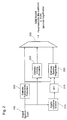
- an encoder 100 processes digital speech 105 (or some other acoustic signal) that may be produced, for example, using a microphone and an analog-to-digital converter.
- the encoder processes this digital speech signal in short frames that are further divided into one or more subframes.
- model parameters are estimated and processed by the encoder and decoder for each subframe.
- each 20 ms frame is divided into two 10 ms subframes, with the frame including 160 samples at a sampling rate of 8 kHz.
- the encoder performs a parameter analysis 110 on the digital speech to estimate MBE model parameters for each subframe of a frame.
- the MBE model parameters include a fundamental frequency (the reciprocal of the pitch period) of the subframe; a set of binary voiced/unvoiced (“V/UV") decisions that characterize the voicing state of the subframe; and a set of spectral magnitudes that characterize the spectral envelope of the subframe.
- the MBE parameter analysis 110 includes processing the digital speech 105 to estimate the fundamental frequency 200 and to estimate voicing decisions 205.
- the parameter analysis 110 also includes applying a window function 210, such as a Hamming window, to the digital input speech.
- the output data of the window function 210 are transformed into spectral coefficients by an FFT 215.
- the spectral coefficients are processed together with the estimated fundamental frequency to estimate the spectral magnitudes 220.
- the estimated fundamental frequency, voicing decisions, and spectral magnitudes are combined 225 to produce the MBE model parameters for each subframe.
- the parameter analysis 110 may employ a filterbank with a non-linear operator to estimate the fundamental frequency and voicing decisions for each subframe.
- the estimation of these excitation parameters is discussed in detail in U.S. Patents Nos. 5,715,365 and 5,826,222 .
- bits are saved by discarding the estimated fundamental frequency and replacing it with a default unvoiced fundamental frequency, which is typically set to approximately half the subframe rate (i.e., 200 Hz).
- the encoder estimates a set of spectral magnitudes for each subframe. With two subframes per frame, two sets of spectral magnitudes are estimated for each frame. The spectral magnitudes are estimated for a subframe by windowing the speech signal using a short overlapping window such as a 155 point Hamming window, and computing an FFT (typically 256 points) on the windowed signal. The energy is then summed around each harmonic of the estimated fundamental frequency, and the square root of the sum is designated as the spectral magnitude for that harmonic. A particular method for estimating the spectral magnitudes is discussed in U.S. Patent No. 5,754,974.
- the voicing decisions, the fundamental frequency, and the set of spectral magnitudes for each of the two subframes form the model parameters for a frame.
- model parameters and the methods used to estimate them are possible. These variations include using alternative or additional model parameters, or changing the rate at which the parameters are estimated.
- the voicing decisions and the fundamental frequency are only estimated once per frame. For example, those parameters may be estimated coincident with the last subframe of the current frame, and then interpolated for the first subframe of the current frame.
- Interpolation of the fundamental frequency may be accomplished by computing the geometric mean between the estimated fundamental frequencies for the last subframes of both the current frame and the immediately prior frame ("the prior frame").
- Interpolation of the voicing decisions may be accomplished by a logical OR operation, which favors voiced over unvoiced, between the estimated decisions for last subframes of the current frame and the prior frame.
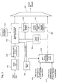
- the encoder employs a quantization block 115 to process the estimated model parameters and the digital speech to produce quantized bits for each frame.
- the encoder uses quantized MBE model parameters to represent voiced regions of a frame, while using separate MCT coefficients to represent unvoiced regions of the frame.
- the encoder then jointly quantizes the model parameters and coefficients for an entire frame using efficient joint quantization techniques.
- the quantization block 115 includes a bit allocation element 300 that uses the quantized voicing information to divide the number of available bits between the MBE model parameter bits and the MCT coefficient bits.
- An MBE model parameter quantizer 305 uses the allocated number of bits to quantize MBE model parameters 310 for the first subframe of a frame and MBE model parameters 315 for the second subframe of the frame to produce quantized model parameter bits 320.
- the quantized model parameter bits 320 are processed by a V/UV element 325 to construct the voicing information and to identify the voiced and/or unvoiced regions of the frame.
- the quantized model parameter bits 320 are also processed by a spectral envelope element 330 to create a spectral envelope of each subframe.
- An element 335 further processes the spectral envelope for a subframe using the output of the V/UV element to set the spectral envelope to zero in voiced regions.
- An element 340 of the quantization block receives the digital speech input and divides it in to into subframes and/or sub sub frames. Each subframe or subsubframe is transformed by a modified cosine transform (MCT) 345 to produce MCT coefficients.
- MCT modified cosine transform
- An MCT coefficient quantizer 350 uses an allocated number of bits to quantize MCT coefficients for unvoiced regions. The MCT coefficient quantizer 350 does this using candidate vectors constructed by an element 355.
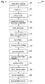
- the quantization may proceed according to a procedure 400 in which the encoder first quantizes the voiced/unvoiced decisions (step 405).
- a vector quantization method described in U.S. Patent Application No. 08/985,262 may be used to jointly quantize the voicing decisions using a small number of bits (typically 3-8).
- performance may be increased by applying variable length coding to the voicing decisions, where only a single bit is used to represent frames that are entirely unvoiced and additional voicing bits are used only if the frame is at least partially voiced.
- the voicing decisions are quantized first since they influence the bit allocation for the remaining components of the frame.
- the encoder uses the next (typically 6-16) bits to quantize the fundamental frequencies for the subframes (step 415).
- the fundamental frequencies from the two subframes are quantized jointly using the method disclosed in U.S. Patent Application No. 08/985,262.
- the fundamental frequency is quantized using a scalar log uniform quantizer over a pitch range of approximately 19 to 123 samples.
- no bits are used to quantize the fundamental frequency, since the default unvoiced fundamental frequency is known by both the encoder and the decoder.
- the encoder quantizes the sets of spectral magnitudes for the two subframes of the frame (step 420). For example, the encoder may convert them into the log domain using logarithmic companding (step 425), and then may use a combination of prediction, block transforms, and vector quantization.
- One approach is to first quantize the second log spectral magnitudes (i.e., the log spectral magnitudes for the second subframe) (step 430) and to then interpolate between the quantized second log spectral magnitudes for both the current frame and the prior frame (step 435).
- the decoder uses both this quantized difference and the second log spectral magnitudes from both the prior frame and the current frame to repeat the interpolation, add the difference, and thereby reconstruct the quantized first log spectral magnitudes for the current frame.
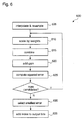
- the second log spectral magnitudes may be quantized (step 430) according to the procedure 500 illustrated in Fig. 5, which includes estimating a set of predicted log magnitudes, subtracting the predicted magnitudes from the actual magnitudes, and then quantizing the resulting set of prediction residuals (i.e., the differences).
- the predicted log amplitudes are formed by interpolating and resampling previously-quantized second log spectral magnitudes from the prior frame (step 505). Linear interpolation is applied with resampling at multiples of the ratio between the fundamental frequencies for the second subframes of the previous frame and the current frame. This interpolation compensates for changes in the fundamental frequency between the two subframes.
- the predicted log amplitudes are scaled by a value less than unity (0.65 is typical) (step 510) and the mean is removed (step 515) before they are subtracted from the second log spectral magnitudes (step 520).
- the resulting prediction residuals are divided into a small number of blocks (typically 4) (step 525).
- the number of spectral magnitudes which equals the number of prediction residuals, varies from frame to frame depending on the bandwidth (typically 3.5 - 4 kHz) divided by the fundamental frequency. Since, for typical human speech, the fundamental frequency varies between about 60 and 400 Hz, the number of spectral magnitudes is allowed to vary over a similarly wide range (9 to 56 is typical), and the quantizer accounts for this variability.
- a Discrete Cosine Transform is applied to the prediction residuals in each block (step 530).
- the size of each block is set as a fraction of the number of spectral magnitudes for the pair of subframes, with the block sizes typically increasing from low frequency to high frequency, and the sum of the block sizes equaling the number of spectral magnitudes for the pair of subframes, (0.2, 0.225, 0.275, 0.3 are typical fractions with four blocks).
- the first two elements from each of the four blocks are then used to form an eight-element prediction residual block average (PRBA) vector (step 535).
- PRBA prediction residual block average
- the DCT then is computed for the PRBA vector (step 540).
- the first (i.e., DC) coefficient is regarded as the gain term, and is quantized separately, typically with a 4-7 bit scalar quantizer (step 545).
- the remaining seven elements in the transformed PRBA vector are then vector quantized (step 550), where a 2-3 part split vector quantizer is commonly used (typically 9 bits for the first three elements plus 7 bits for the last four elements).
- the remaining higher order coefficients (HOCs) from each of the four DCT blocks are quantized (step 555).
- HOCs higher order coefficients
- no more than four HOCs from any block are quantized. Any additional HOCs are set equal to zero and are not encoded.
- the HOC quantization is typically done with a vector quantizer using approximately four bits per block.
- the resulting bits are added to the encoder output bits for the current frame (step 560), and the steps are reversed to compute at the encoder the quantized spectral magnitudes as seen by the decoder (step 565).
- the encoder stores these quantized spectral magnitudes (step 570) for use in quantizing the first log spectral magnitudes of the current frame and for subsequent frames to only use information available to both the encoder and the decoder.
- _ these quantized spectral magnitudes may be subtracted from the unquantized second log spectral magnitudes and this set of spectral errors may be further quantized if more precise quantization is required.
- the quantization of the first log spectral magnitudes is accomplished according to a procedure 600 that includes interpolating between the quantized second log spectral magnitudes for both the current frame and the prior frame.
- some small number of different candidate interpolated spectral magnitudes are formed using three parameters consisting of a pair of nonnegative weights and a gain term.
- Each of the candidate interpolated spectral magnitudes are compared against the unquantized first log spectral magnitudes and the one which yields the minimum squared error is selected as the best candidate.
- the different candidate interpolated spectral magnitudes are formed by first interpolating and resampling the previously-quantized second log spectral magnitudes for both the current and prior frame to account for changes in the fundamental frequency between the three subframes (step 605).
- Each of the candidate interpolated spectral magnitudes then is formed by scaling each of the two resampled sets by one of the two weights (step 610), adding the scaled sets together (step 615), and adding the constant gain term (step 620).
- the number of different candidate interpolated spectral magnitudes that are computed is equal to some small power of two (e.g., 2, 4, 8, 16, or 32), with the weights and gain terms being stored in a table of that size.
- Each set is evaluated by computing the squared error between it and the first log spectral magnitudes which are being quantized (step 625).
- the set of interpolated spectral magnitudes which produces the smallest error is selected (step 630) and the index into the table of weights is added to the output bits for the current frame (step 635).
- the selected set of interpolated spectral magnitudes then are subtracted from the first log spectral magnitudes being quantized to produce a set of spectral errors (step 640). As discussed below, this set of spectral errors may be further quantized for more precision.
- More precise quantization of the model parameters can be achieved in many ways.
- one method which is advantageous in certain applications is to use multiple layers of quantization, where the second layer quantizes the error between the unquantized parameter and the result of the first layer, and additional layers work in a similar manner.
- This hierarchical approach may be applied to the quantization of the spectral magnitudes, where a second layer of quantization is applied to the spectral errors computed as a result of the first layer of quantization described above.
- a second quantization layer is achieved by transforming the spectral errors with a DCT and using a vector quantizer to quantize some number of these DCT coefficients.
- a typical approach is to use a gain quantizer for the first coefficient plus split vector quantization of the subsequent coefficients.
- a second level of quantization may be performed on the spectral errors by first adaptively allocating the desired number of additional bits depending on the quantized prediction residuals computed during the reconstruction of the quantized second log spectral magnitudes for the current frame.
- more bits are allocated where the prediction residuals are larger, typically adding one extra bit whenever the residual (which is in the log domain) increases by a certain amount (such as 0.67).
- This bit allocation method differs from prior techniques in that the bit allocation is based on the prediction residuals rather than on the log spectral magnitudes themselves. This has the advantage of eliminating the sensitivity of the bit allocation to bit errors in prior frames, which results in higher performance in noisy communication channels.
- VQ vector quantization
- the encoder computes a modified cosine transform (MCT) or other spectral transform of the speech for each subframe (step 450).
- MCT modified cosine transform
- TDAC time domain aliasing cancellation
- the MCT or similar transform is typically used to represent unvoiced speech, due tc its desirable properties for this purpose.
- the MCT is a member of a class of overlapped orthogonal transforms that are capable of perfect reconstruction while maintaining critical sampling. These properties are quite significant for a number of reasons. First, an overlapping window allows smooth transitions between subframes, eliminates audible noisy at the subframe rate, and enables good voiced/unvoiced transitions. In addition, the perfect reconstruction property prevents the transform itself from introducing any artifacts into the decoded speech. Finally, critical sampling maintains the same number of transform coefficients as input samples, thereby leaving more bits available to quantize each coefficient.
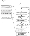
- the encoder generates the spectral transform according to the procedure 700 illustrated in Fig. 7.
- the quantized set of log spectral magnitudes is interpolated or resampled to match the center of each MCT bin (step 705).
- the spectral envelope is set to zero (or significantly attenuated) for any bin which is in
- the MCT coefficients then are quantized (step 455) using a vector quantizer that searches for a combination of one or more candidate vectors which, when interleaved together and multiplied by the computed spectral envelope, maximize the correlation against the actual MCT coefficients for that subframe (step 715).
- the candidate vectors are constructed from an offset into a long prototype vector and by a predetermined number of sign bits which scale every M'th element of the vector by +/- 1 (where M is the number of sign bits per candidate vector).
- M is the number of possible offsets for a candidate vector is limited to a reasonable number, such as 256 (i.e., 8 bits), and any additional bits are used as sign bits. For example, if eleven bits are to be used for a candidate vector, eight bits would be used for the offset and the remaining three bits would be sign bits, with each sign bit either inverting or not inverting the sign of every third element of the candidate vector.
- interleaving is used to combine all of the candidate vectors for a subframe (step 720).
- Each successive element in a candidate vector is interleaved to every N'th MCT bin, where N is the number of candidate vectors.
- N the number of candidate vectors.
- the interleaved candidate vectors are then multiplied by the spectral envelope (step 725) and scaled by a quantized scale factor ⁇ i to reconstruct the MCT coefficients for each subframe.
- Sign bits then are computed and signs are flipped (step 730). Once this is done, a correlation is computed (step 735). If there are no more combinations of candidate vectors to be considered (step 740), the combination with the highest correlation is selected (step 745) and the offset and sign bits are added to the output bits (step 750).
- the process of finding the best candidate vectors for any subframe requires that each possible combination of N candidate vectors be scaled by the spectral envelope and compared against the unquantized MCT coefficients until the possibility with the highest correlation is found. Searching all possible combinations of N candidate vectors requires that, for each candidate, all possible offsets into the prototype vector and all possible sign bits are considered. However, in the case of the sign bits, it is possible to determine the best setting for each sign bit by setting it so that the elements affected by that bit are positively correlated with the corresponding unquantized MCT coefficients, leaving only the possible offsets to be searched.
- a partial search process can be used to find a good combination of N candidate vectors at a much lower complexity.
- a partial search process used in one implementation preselects the best few (3-8) possibilities for each candidate vector, tries all combinations of the preselected candidate vectors, and selects the combination with the highest correlation as the final selection.
- the bits used to encode the selected combination include the offset bits and the sign bits for each of the N candidate vectors interleaved into that combination.
- a scale factor ⁇ i for the i'th subframe is computed (step 755) to minimize the mean square error between the unquantized MCT coefficients and the selected candidates vectors: where C i (k) represents the combined candidate vectors, H i (k) is the spectral envelope, and S i (k) is the unquantized MCT coefficients for the i'th subframe.
- scale factors are then quantized in pairs (step 720), typically with a vector quantizer that uses a small number of bits (e.g., 1-6) per pair.
- a vector quantizer that uses a small number of bits (e.g., 1-6) per pair.
- the number of bits allocated to each candidate vector typically two per subframe
- to the scale factors typically one per subframe
- the encoder may optionally process the quantized bits with a forward error control (FEC) coder 120 to produce output bits 125 for a frame.
- FEC forward error control
- These output bits may be, for example, transmitted to a decoder or stored for later processing.
- a combiner 360 combines the quantized MCT coefficient bits and the quantized model parameter bits to produce the output bits for the frame.
- the encoder divides the input digital speech signal into 20 ms frames consisting of 160 samples at an 8kHz sampling rate. Each frame is further divided into two 10 ms subframes. Each frame is encoded with 80 bits of which some or all are used to quantize the MBE model parameters as shown in Table 1. Two separate cases are considered depending on whether the frame is entirely unvoiced (i.e., the All Unvoiced Case) or if the frame is partially voiced (i.e., the Some Voiced Case). The first voicing bit, designated the All Unvoiced Bit, indicates to the decoder which case is being used for the frame. Remaining bits are then allocated as shown in Table 1 for the appropriate case.
- the gain term is either quantized with four bits or six bits, while the PRBA vector is always quantized with a nine bit plus a seven bit split vector quantizer for a total of sixteen bits.
- the HOCs are always quantized with four 4-bit quantizers (one per block) for a total of sixteen bits.
- the Some Voice Case uses three bits for selecting the interpolation weights and gain term that best match the first log spectral magnitudes.
- the total bits per frame used to quantize the model parameters in the All Unvoiced Case is 37, leaving 43 bits for the MCT coefficients.
- 39 bits are used to indicate the offset and sign bits for the combination of four candidate vectors which are selected (two candidates per subframe, with eight offset bits per candidate, two sign bits for three candidates, and one sign bit for the fourth candidate), while the final four bits are used to quantize the associated MCT scale factors using two 2-bit vector quantizers.
- the method of representing and quantizing unvoiced sounds with transform coefficients is subject to many variations.
- various other transforms can be substituted for the MCT described above.
- the MCT or other transform coefficients can be quantized with various methods including use of adaptive bit allocation, scalar quantization, and vector quantization (including algebraic, multi-stage, split VQ or structured codebook) techniques.
- the frame structure of the MCT coefficients can be changed such that they do not share the same subframe structure as the model parameters (i.e., one set of subframes for the MCT coefficients and another set of subframes for the model parameters). In one important variation, each subframe is divided into two subsubframes, and a separate MCT transform is applied to each subsubframe.
- the techniques include further refinements, such as attenuating the spectral envelope or setting it to zero in low frequency unvoiced regions.
- setting the spectral envelope to zero for the first few hundred Hertz (200-400 Hz is typical) results in improved performance since unvoiced energy is not perceptually important in this frequency range, while background noise tends to be prevalent.
- the techniques are well suited to application of noise removal methods that can operate on the MCT coefficients and spectral magnitudes and take advantage of the voicing information available at the encoder.
- the techniques feature the ability to operate in either a fixed rate or variable rate mode.
- a fixed rate mode each frame is designed to use the same number of bits (i.e., 80 bits per 20 ms frame for a 4000 bps vocoder), while in a variable rate mode, the encoder selects the rate (i.e., the number of bits per frame) from a set of possible options.
- the rate i.e., the number of bits per frame
- Rate selection may be based on a number of signal measurements to achieve the highest quality at the lowest average rate, and may be enhanced further by incorporating optional voice/silence discrimination.
- the techniques accommodate either fixed or variable rate operation due to this bit allocation method.
- the techniques allocate bits to try to make effective use of all available bits without incurring excessive sensitivity to bit errors which may have occurred in the previous frames.
- Bit allocation is constrained by the total number of bits for the current frame and is considered as parameter supplied to both the encoder and decoder.
- the total number of bits is a constant determined by desired bit rate and the frame size, while in the case of variable rate operation the total bits are set by the rate selection algorithm, so in either case it case be considered as an externally supplied parameter.
- the encoder subtracts from the total bits the number of bits used initially to quantize the MBE model parameters, including the voicing decisions, the fundamental frequency (zero if all unvoiced), and the first layer of quantization for the sets of spectral magnitudes.
- the remaining bits are then used for additional layers of quantization for the spectral magnitudes, for quantizing the subframe MCT coefficients, or for both.
- all of the remaining bits typically are applied to the MCT coefficients.
- all of the remaining bits typically are allocated to additional layers of quantization for the spectral magnitudes or other MBE model parameters.
- the remaining bits are generally split in relative proportion to the number of voiced and unvoiced frequency bands in the frame. This process allows the remaining bits to be used where they are most effective in achieving high voice quality, while basing the bit allocation on information previously coded within the frame to eliminate sensitivity to bit errors in previous frames.
- a decoder 800 processes an input bit stream 805.
- the input bit stream 805 includes sets of bits generated by the encoder 100. Each set corresponds to an encoded frame of the digital signal 105.
- the bit stream may be produced, for example, by a receiver that receives bits transmitted by the encoder, or retrieved from a storage device.
- the encoder 100 When the encoder 100 has encoded the bits using an FEC coder, the set of input bits for a frame is supplied to an FEC decoder 810.
- the FEC decoder 810 decodes the bits to produce a set of quantized bits.
- the decoder performs parameter reconstruction 815 on the quantized bits to reconstruct the MBE model parameters for the frame.
- the decoder also performs MCT coefficient reconstruction 820 to reconstruct the transform coefficients corresponding to the unvoiced portion of the frame.
- the decoder separately performs a voiced synthesis 825 and an unvoiced synthesis 830.
- the decoder then adds 835 the results to produce a digital speech output 840 for the frame which is suitable for playback through a digital-to-analog converter and a loudspeaker.
- the operation of the decoder is generally the inverse of the encoder in order to reconstruct the MBE model parameters and the MCT coefficients for each subframe from the bits output by the encoder, and to then synthesize a frame of speech from the reconstructed information.
- the decoder first reconstructs the excitation parameters consisting of the voicing decisions and the fundamental frequencies for all the subframes in the frame. In the case where only a single set of voicing decisions and a single fundamental frequency are estimated encoded for the entire frame, then the decoder interpolates with like data received for the prior frame to reconstruct a fundamental frequency and voicing decisions for intermediate subframes in the same manner as the encoder.
- the decoder sets the fundamental frequency to the default unvoiced value.
- the decoder next reconstructs all of the spectral magnitudes by inverting the quantization process used by the encoder.
- the decoder is able to recompute the bit allocation as performed by the encoder, so all layers of quantization used by the encoder can be used by the decoder in reconstructing the spectral magnitudes.
- the decoder regenerates the MCT coefficients for each subframe (or subsubframe in the case where more than one MCT transform is performed per subframe).
- the decoder reconstructs a spectral envelope for each subframe in the same way that the encoder did.
- the decoder then multiplies this spectral envelope by the interleaved candidate vectors indicated by the encoded offsets and sign bits.
- the decoder scales the MCT coefficients for each subframe by the appropriate decoded scale factor.
- the decoder then computes an inverse MCT using a TDAC window w(n) to produce the output y i (n) for the i'th subframe:
- the voiced signal is then synthesized separately by the decoder using a bank of harmonic oscillators with one oscillator assigned to each harmonic.
- the voiced speech is synthesized one subframe at a time in order to coincide with the representation used for the model parameters.
- a synthesis boundary then occurs between each subframe, and the voiced synthesis method must ensure that no audible discontinuities are introduced at these subframe boundaries. This continuity condition forces each harmonic oscillator to interpolate between the model parameters representing successive subframes.
- each harmonic oscillator is normally constrained to be a linear polynomial.
- the parameters of the linear amplitude polynomial are set such that the amplitude is interpolated between corresponding spectral magnitudes across the subframe. This generally follows a simple ordered assignment of the harmonics (e.g., the first oscillator interpolates between the first spectral magnitudes in the prior and current subframe, the second oscillator interpolates between the second spectral magnitude in the current and prior subframe, and so on until all spectral magnitudes are used).
- the amplitude polynomial is matched to zero at one end or the other rather than to one of the spectral magnitudes.
- each harmonic oscillator is constrained to be a quadratic or cubic polynomial and the polynomial coefficients are selected such that the phase and its derivative are matched to the desired phase and frequency values at both the beginning and ending subframe boundary.
- the desired phases at the subframe boundaries are determined either from explicitly transmitted phase information or by a number of phase regeneration methods.
- the desired frequency at the subframe boundaries for the 1'th harmonic oscillator is simply equal to 1 times the fundamental.
- the output of each harmonic oscillator is summed for each subframe in the frame, and the result is then added to the unvoiced speech to complete the synthesized speech for the current frame. Complete details of this procedure are described in the incorporated references. Repeating this synthesis process for a series of consecutive frames allows a continuous digital speech signal to be produced which is output to a digital-to-analog converter for subsequent playback through a conventional speaker.
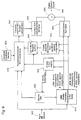
- the decoder receives an input bit stream 900 for each frame.
- a bit allocator 905 uses reconstructed voicing information to supply bit allocation information to an MBE model parameter reconstructor 910 and an MCT coefficient reconstructor 915.
- the MBE model parameter reconstructor 910 processes the bit stream 900 to reconstruct the MBE model parameters for all of the subframes in the frame using the supplied bit allocation information.
- a V/UV element 920 processes the reconstructed model parameters to generate the reconstructed voicing information and to identify voiced and unvoiced regions.
- a spectral envelope element 925 processes the reconstructed model parameters to create a spectral envelope from the spectral magnitudes. The spectral envelope is further processed by an element 930 to set the voiced regions to zero.
- the MCT coefficient reconstructor 915 uses the bit allocation information, the identified voicing regions, the processed spectral envelope, and a table of candidate vectors 935 to reconstruct the MCT coefficients from the input bits for each subframe or subsubframe. An inverse MCT 940 then is performed for each subsubframe.
- the outputs of the MCT 940 are combined by an overlap-add element 945 to produce the unvoiced speech for the frame.
- a voiced speech synthesizer 950 synthesizes voiced speech using the reconstructed MBE model parameters.
- a summer 955 adds the voiced and unvoiced speech to produce the digital speech output 960 which is suitable for playback via a digital-to-analog converter and a loudspeaker.
- the voiced synthesis procedure sets the amplitude of that harmonic to zero at the subframe boundary corresponding to the unvoiced subframe. This is accomplished by matching the amplitude polynomial to zero at the unvoiced end.
- the technique differs from prior techniques in that a linear or piecewise linear polynomial is not used for the amplitude polynomial whenever a harmonic undergoes such a voicing transition. Instead, the square of the same MCT window used for synthesizing the unvoiced speech is used. Such use of a consistent window between the voiced and unvoiced synthesis methods assures that transition is handled smoothly without the introduction of additional artifacts.
- phase regeneration can be used at the decoder to produce the phase information necessary for synthesizing the voiced speech without requiring explicit encoding and transmission of any phase information.
- phase regeneration methods compute an approximate phase signal from other decoded model parameters.
- random phase values are computed using the decoded fundamental frequencies and voicing decisions.
- the harmonic phases at the subframe boundaries are regenerated at the decoder from the spectral magnitudes by applying a smoothing kernel to the log spectral magnitudes or by performing a minimum phase or similar magnitude-based phase reconstruction.
Applications Claiming Priority (2)
| Application Number | Priority Date | Filing Date | Title |
|---|---|---|---|
| US09/447,958 US6377916B1 (en) | 1999-11-29 | 1999-11-29 | Multiband harmonic transform coder |
| US447958 | 1999-11-29 |
Publications (2)
| Publication Number | Publication Date |
|---|---|
| EP1103955A2 true EP1103955A2 (fr) | 2001-05-30 |
| EP1103955A3 EP1103955A3 (fr) | 2002-08-07 |
Family
ID=23778441
Family Applications (1)
| Application Number | Title | Priority Date | Filing Date |
|---|---|---|---|
| EP00310507A Withdrawn EP1103955A3 (fr) | 1999-11-29 | 2000-11-27 | Codeur de parole hybride harmonique-transformation |
Country Status (4)
| Country | Link |
|---|---|
| US (1) | US6377916B1 (fr) |
| EP (1) | EP1103955A3 (fr) |
| JP (1) | JP2001222297A (fr) |
| AU (1) | AU7174100A (fr) |
Cited By (4)
| Publication number | Priority date | Publication date | Assignee | Title |
|---|---|---|---|---|
| EP1329877A2 (fr) * | 2002-01-16 | 2003-07-23 | Digital Voice Systems, Inc. | Synthèse et décodage de la parole |
| RU2445718C1 (ru) * | 2010-08-31 | 2012-03-20 | Государственное образовательное учреждение высшего профессионального образования Академия Федеральной службы охраны Российской Федерации (Академия ФСО России) | Способ выделения сегментов обработки речи на основе анализа корреляционных зависимостей в речевом сигнале |
| RU2684576C1 (ru) * | 2018-01-31 | 2019-04-09 | Федеральное государственное казенное военное образовательное учреждение высшего образования "Академия Федеральной службы охраны Российской Федерации" (Академия ФСО России) | Способ выделения сегментов обработки речи на основе последовательного статистического анализа |
| EP4088277A4 (fr) * | 2020-01-08 | 2023-02-15 | Digital Voice Systems, Inc. | Codage de la parole utilisant une interpolation variant dans le temps |
Families Citing this family (43)
| Publication number | Priority date | Publication date | Assignee | Title |
|---|---|---|---|---|
| US6064955A (en) * | 1998-04-13 | 2000-05-16 | Motorola | Low complexity MBE synthesizer for very low bit rate voice messaging |
| US7295974B1 (en) * | 1999-03-12 | 2007-11-13 | Texas Instruments Incorporated | Encoding in speech compression |
| US7092881B1 (en) * | 1999-07-26 | 2006-08-15 | Lucent Technologies Inc. | Parametric speech codec for representing synthetic speech in the presence of background noise |
| US7222070B1 (en) * | 1999-09-22 | 2007-05-22 | Texas Instruments Incorporated | Hybrid speech coding and system |
| US6975984B2 (en) * | 2000-02-08 | 2005-12-13 | Speech Technology And Applied Research Corporation | Electrolaryngeal speech enhancement for telephony |
| US7337107B2 (en) * | 2000-10-02 | 2008-02-26 | The Regents Of The University Of California | Perceptual harmonic cepstral coefficients as the front-end for speech recognition |
| US6633839B2 (en) | 2001-02-02 | 2003-10-14 | Motorola, Inc. | Method and apparatus for speech reconstruction in a distributed speech recognition system |
| US6738739B2 (en) * | 2001-02-15 | 2004-05-18 | Mindspeed Technologies, Inc. | Voiced speech preprocessing employing waveform interpolation or a harmonic model |
| US7243295B2 (en) * | 2001-06-12 | 2007-07-10 | Intel Corporation | Low complexity channel decoders |
| WO2003019533A1 (fr) * | 2001-08-24 | 2003-03-06 | Kabushiki Kaisha Kenwood | Dispositif et procede d'interpolation adaptive de composantes de frequence d'un signal |
| JP2005510925A (ja) * | 2001-11-30 | 2005-04-21 | コーニンクレッカ フィリップス エレクトロニクス エヌ ヴィ | 信号コード化 |
| US7421304B2 (en) * | 2002-01-21 | 2008-09-02 | Kenwood Corporation | Audio signal processing device, signal recovering device, audio signal processing method and signal recovering method |
| US7764716B2 (en) * | 2002-06-21 | 2010-07-27 | Disney Enterprises, Inc. | System and method for wirelessly transmitting and receiving digital data using acoustical tones |
| KR100462611B1 (ko) * | 2002-06-27 | 2004-12-20 | 삼성전자주식회사 | 하모닉 성분을 이용한 오디오 코딩방법 및 장치 |
| US7970606B2 (en) * | 2002-11-13 | 2011-06-28 | Digital Voice Systems, Inc. | Interoperable vocoder |
| KR100467326B1 (ko) * | 2002-12-09 | 2005-01-24 | 학교법인연세대학교 | 추가 비트 할당 기법을 이용한 음성 부호화 및 복호화를위한 송수신기 |
| US7634399B2 (en) * | 2003-01-30 | 2009-12-15 | Digital Voice Systems, Inc. | Voice transcoder |
| US6915256B2 (en) * | 2003-02-07 | 2005-07-05 | Motorola, Inc. | Pitch quantization for distributed speech recognition |
| US6961696B2 (en) * | 2003-02-07 | 2005-11-01 | Motorola, Inc. | Class quantization for distributed speech recognition |
| US8359197B2 (en) * | 2003-04-01 | 2013-01-22 | Digital Voice Systems, Inc. | Half-rate vocoder |
| US7272557B2 (en) * | 2003-05-01 | 2007-09-18 | Microsoft Corporation | Method and apparatus for quantizing model parameters |
| DE10328777A1 (de) * | 2003-06-25 | 2005-01-27 | Coding Technologies Ab | Vorrichtung und Verfahren zum Codieren eines Audiosignals und Vorrichtung und Verfahren zum Decodieren eines codierten Audiosignals |
| US20050065787A1 (en) * | 2003-09-23 | 2005-03-24 | Jacek Stachurski | Hybrid speech coding and system |
| CN101176147B (zh) * | 2005-05-13 | 2011-05-18 | 松下电器产业株式会社 | 语音编码装置以及频谱变形方法 |
| KR100647336B1 (ko) * | 2005-11-08 | 2006-11-23 | 삼성전자주식회사 | 적응적 시간/주파수 기반 오디오 부호화/복호화 장치 및방법 |
| US7953595B2 (en) * | 2006-10-18 | 2011-05-31 | Polycom, Inc. | Dual-transform coding of audio signals |
| KR101565919B1 (ko) * | 2006-11-17 | 2015-11-05 | 삼성전자주식회사 | 고주파수 신호 부호화 및 복호화 방법 및 장치 |
| EP1927981B1 (fr) * | 2006-12-01 | 2013-02-20 | Nuance Communications, Inc. | Affinement spectral de signaux audio |
| US8036886B2 (en) * | 2006-12-22 | 2011-10-11 | Digital Voice Systems, Inc. | Estimation of pulsed speech model parameters |
| JP4708446B2 (ja) * | 2007-03-02 | 2011-06-22 | パナソニック株式会社 | 符号化装置、復号装置およびそれらの方法 |
| US7774205B2 (en) * | 2007-06-15 | 2010-08-10 | Microsoft Corporation | Coding of sparse digital media spectral data |
| US7761290B2 (en) * | 2007-06-15 | 2010-07-20 | Microsoft Corporation | Flexible frequency and time partitioning in perceptual transform coding of audio |
| US8369638B2 (en) * | 2008-05-27 | 2013-02-05 | Microsoft Corporation | Reducing DC leakage in HD photo transform |
| US8447591B2 (en) * | 2008-05-30 | 2013-05-21 | Microsoft Corporation | Factorization of overlapping tranforms into two block transforms |
| US20100106269A1 (en) * | 2008-09-26 | 2010-04-29 | Qualcomm Incorporated | Method and apparatus for signal processing using transform-domain log-companding |
| US8275209B2 (en) * | 2008-10-10 | 2012-09-25 | Microsoft Corporation | Reduced DC gain mismatch and DC leakage in overlap transform processing |
| US8805694B2 (en) * | 2009-02-16 | 2014-08-12 | Electronics And Telecommunications Research Institute | Method and apparatus for encoding and decoding audio signal using adaptive sinusoidal coding |
| EP2249333B1 (fr) * | 2009-05-06 | 2014-08-27 | Nuance Communications, Inc. | Procédé et appareil d'évaluation d'une fréquence fondamentale d'un signal vocal |
| WO2011013244A1 (fr) * | 2009-07-31 | 2011-02-03 | 株式会社東芝 | Appareil de traitement audio |
| CN102577114B (zh) * | 2009-10-20 | 2014-12-10 | 日本电气株式会社 | 多带域压缩器 |
| US20110257978A1 (en) * | 2009-10-23 | 2011-10-20 | Brainlike, Inc. | Time Series Filtering, Data Reduction and Voice Recognition in Communication Device |
| WO2012081166A1 (fr) * | 2010-12-14 | 2012-06-21 | パナソニック株式会社 | Dispositif de codage, dispositif de décodage et procédés associés |
| US9236058B2 (en) * | 2013-02-21 | 2016-01-12 | Qualcomm Incorporated | Systems and methods for quantizing and dequantizing phase information |
Citations (1)
| Publication number | Priority date | Publication date | Assignee | Title |
|---|---|---|---|---|
| EP0590155A1 (fr) * | 1992-03-18 | 1994-04-06 | Sony Corporation | Procede de codage a haute efficacite |
Family Cites Families (44)
| Publication number | Priority date | Publication date | Assignee | Title |
|---|---|---|---|---|
| US3706929A (en) | 1971-01-04 | 1972-12-19 | Philco Ford Corp | Combined modem and vocoder pipeline processor |
| US3982070A (en) | 1974-06-05 | 1976-09-21 | Bell Telephone Laboratories, Incorporated | Phase vocoder speech synthesis system |
| US3975587A (en) | 1974-09-13 | 1976-08-17 | International Telephone And Telegraph Corporation | Digital vocoder |
| US4091237A (en) | 1975-10-06 | 1978-05-23 | Lockheed Missiles & Space Company, Inc. | Bi-Phase harmonic histogram pitch extractor |
| US4422459A (en) | 1980-11-18 | 1983-12-27 | University Patents, Inc. | Electrocardiographic means and method for detecting potential ventricular tachycardia |
| ATE15415T1 (de) | 1981-09-24 | 1985-09-15 | Gretag Ag | Verfahren und vorrichtung zur redundanzvermindernden digitalen sprachverarbeitung. |
| AU570439B2 (en) | 1983-03-28 | 1988-03-17 | Compression Labs, Inc. | A combined intraframe and interframe transform coding system |
| NL8400728A (nl) | 1984-03-07 | 1985-10-01 | Philips Nv | Digitale spraakcoder met basisband residucodering. |
| US4583549A (en) | 1984-05-30 | 1986-04-22 | Samir Manoli | ECG electrode pad |
| US4622680A (en) | 1984-10-17 | 1986-11-11 | General Electric Company | Hybrid subband coder/decoder method and apparatus |
| US4885790A (en) | 1985-03-18 | 1989-12-05 | Massachusetts Institute Of Technology | Processing of acoustic waveforms |
| US5067158A (en) | 1985-06-11 | 1991-11-19 | Texas Instruments Incorporated | Linear predictive residual representation via non-iterative spectral reconstruction |
| US4879748A (en) | 1985-08-28 | 1989-11-07 | American Telephone And Telegraph Company | Parallel processing pitch detector |
| US4720861A (en) | 1985-12-24 | 1988-01-19 | Itt Defense Communications A Division Of Itt Corporation | Digital speech coding circuit |
| US4797926A (en) | 1986-09-11 | 1989-01-10 | American Telephone And Telegraph Company, At&T Bell Laboratories | Digital speech vocoder |
| US5054072A (en) | 1987-04-02 | 1991-10-01 | Massachusetts Institute Of Technology | Coding of acoustic waveforms |
| US5095392A (en) | 1988-01-27 | 1992-03-10 | Matsushita Electric Industrial Co., Ltd. | Digital signal magnetic recording/reproducing apparatus using multi-level QAM modulation and maximum likelihood decoding |
| US5023910A (en) | 1988-04-08 | 1991-06-11 | At&T Bell Laboratories | Vector quantization in a harmonic speech coding arrangement |
| US4821119A (en) | 1988-05-04 | 1989-04-11 | Bell Communications Research, Inc. | Method and apparatus for low bit-rate interframe video coding |
| US4979110A (en) | 1988-09-22 | 1990-12-18 | Massachusetts Institute Of Technology | Characterizing the statistical properties of a biological signal |
| JPH0782359B2 (ja) | 1989-04-21 | 1995-09-06 | 三菱電機株式会社 | 音声符号化装置、音声復号化装置及び音声符号化・復号化装置 |
| DE69029120T2 (de) | 1989-04-25 | 1997-04-30 | Toshiba Kawasaki Kk | Stimmenkodierer |
| US5036515A (en) | 1989-05-30 | 1991-07-30 | Motorola, Inc. | Bit error rate detection |
| US5081681B1 (en) | 1989-11-30 | 1995-08-15 | Digital Voice Systems Inc | Method and apparatus for phase synthesis for speech processing |
| US5226108A (en) | 1990-09-20 | 1993-07-06 | Digital Voice Systems, Inc. | Processing a speech signal with estimated pitch |
| US5216747A (en) | 1990-09-20 | 1993-06-01 | Digital Voice Systems, Inc. | Voiced/unvoiced estimation of an acoustic signal |
| US5226084A (en) | 1990-12-05 | 1993-07-06 | Digital Voice Systems, Inc. | Methods for speech quantization and error correction |
| US5247579A (en) | 1990-12-05 | 1993-09-21 | Digital Voice Systems, Inc. | Methods for speech transmission |
| JP3297749B2 (ja) * | 1992-03-18 | 2002-07-02 | ソニー株式会社 | 符号化方法 |
| US5517511A (en) | 1992-11-30 | 1996-05-14 | Digital Voice Systems, Inc. | Digital transmission of acoustic signals over a noisy communication channel |
| US5517595A (en) * | 1994-02-08 | 1996-05-14 | At&T Corp. | Decomposition in noise and periodic signal waveforms in waveform interpolation |
| JPH07225597A (ja) * | 1994-02-15 | 1995-08-22 | Hitachi Ltd | 音響信号符号化、復号化方法及び装置 |
| TW295747B (fr) * | 1994-06-13 | 1997-01-11 | Sony Co Ltd | |
| CA2154911C (fr) | 1994-08-02 | 2001-01-02 | Kazunori Ozawa | Dispositif de codage de paroles |
| US5774837A (en) * | 1995-09-13 | 1998-06-30 | Voxware, Inc. | Speech coding system and method using voicing probability determination |
| US5806038A (en) | 1996-02-13 | 1998-09-08 | Motorola, Inc. | MBE synthesizer utilizing a nonlinear voicing processor for very low bit rate voice messaging |
| US6014622A (en) | 1996-09-26 | 2000-01-11 | Rockwell Semiconductor Systems, Inc. | Low bit rate speech coder using adaptive open-loop subframe pitch lag estimation and vector quantization |
| US6131084A (en) * | 1997-03-14 | 2000-10-10 | Digital Voice Systems, Inc. | Dual subframe quantization of spectral magnitudes |
| US6161089A (en) * | 1997-03-14 | 2000-12-12 | Digital Voice Systems, Inc. | Multi-subframe quantization of spectral parameters |
| JP2001507822A (ja) * | 1997-09-30 | 2001-06-12 | シーメンス・アクチエンゲゼルシャフト | スピーチ信号のエンコード方法 |
| US6199037B1 (en) * | 1997-12-04 | 2001-03-06 | Digital Voice Systems, Inc. | Joint quantization of speech subframe voicing metrics and fundamental frequencies |
| US6094629A (en) * | 1998-07-13 | 2000-07-25 | Lockheed Martin Corp. | Speech coding system and method including spectral quantizer |
| US6138092A (en) * | 1998-07-13 | 2000-10-24 | Lockheed Martin Corporation | CELP speech synthesizer with epoch-adaptive harmonic generator for pitch harmonics below voicing cutoff frequency |
| US6119082A (en) * | 1998-07-13 | 2000-09-12 | Lockheed Martin Corporation | Speech coding system and method including harmonic generator having an adaptive phase off-setter |
-
1999
- 1999-11-29 US US09/447,958 patent/US6377916B1/en not_active Expired - Lifetime
-
2000
- 2000-11-22 AU AU71741/00A patent/AU7174100A/en not_active Abandoned
- 2000-11-27 EP EP00310507A patent/EP1103955A3/fr not_active Withdrawn
- 2000-11-28 JP JP2000360848A patent/JP2001222297A/ja active Pending
Patent Citations (1)
| Publication number | Priority date | Publication date | Assignee | Title |
|---|---|---|---|---|
| EP0590155A1 (fr) * | 1992-03-18 | 1994-04-06 | Sony Corporation | Procede de codage a haute efficacite |
Non-Patent Citations (2)
| Title |
|---|
| BRANDSTEIN M S ET AL: "A real-time implementation of the improved MBE speech coder" ICASSP 90. 1990 INTERNATIONAL CONFERENCE ON ACOUSTICS, SPEECH AND SIGNAL PROCESSING (CAT. NO.90CH2847-2), ALBUQUERQUE, NM, USA, 3-6 APRIL 1990, pages 5-8 vol.1, XP010003694 1990, New York, NY, USA, IEEE, USA * |
| SHLOMOT E ET AL: "Combined harmonic and waveform coding of speech at low bit rates" ACOUSTICS, SPEECH AND SIGNAL PROCESSING, 1998. PROCEEDINGS OF THE 1998 IEEE INTERNATIONAL CONFERENCE ON SEATTLE, WA, USA 12-15 MAY 1998, NEW YORK, NY, USA,IEEE, US, 12 May 1998 (1998-05-12), pages 585-588, XP010279328 ISBN: 0-7803-4428-6 * |
Cited By (6)
| Publication number | Priority date | Publication date | Assignee | Title |
|---|---|---|---|---|
| EP1329877A2 (fr) * | 2002-01-16 | 2003-07-23 | Digital Voice Systems, Inc. | Synthèse et décodage de la parole |
| EP1329877A3 (fr) * | 2002-01-16 | 2005-01-12 | Digital Voice Systems, Inc. | Synthèse et décodage de la parole |
| US8200497B2 (en) | 2002-01-16 | 2012-06-12 | Digital Voice Systems, Inc. | Synthesizing/decoding speech samples corresponding to a voicing state |
| RU2445718C1 (ru) * | 2010-08-31 | 2012-03-20 | Государственное образовательное учреждение высшего профессионального образования Академия Федеральной службы охраны Российской Федерации (Академия ФСО России) | Способ выделения сегментов обработки речи на основе анализа корреляционных зависимостей в речевом сигнале |
| RU2684576C1 (ru) * | 2018-01-31 | 2019-04-09 | Федеральное государственное казенное военное образовательное учреждение высшего образования "Академия Федеральной службы охраны Российской Федерации" (Академия ФСО России) | Способ выделения сегментов обработки речи на основе последовательного статистического анализа |
| EP4088277A4 (fr) * | 2020-01-08 | 2023-02-15 | Digital Voice Systems, Inc. | Codage de la parole utilisant une interpolation variant dans le temps |
Also Published As
| Publication number | Publication date |
|---|---|
| AU7174100A (en) | 2001-05-31 |
| JP2001222297A (ja) | 2001-08-17 |
| US6377916B1 (en) | 2002-04-23 |
| EP1103955A3 (fr) | 2002-08-07 |
Similar Documents
| Publication | Publication Date | Title |
|---|---|---|
| US6377916B1 (en) | Multiband harmonic transform coder | |
| US8200497B2 (en) | Synthesizing/decoding speech samples corresponding to a voicing state | |
| US8315860B2 (en) | Interoperable vocoder | |
| US5754974A (en) | Spectral magnitude representation for multi-band excitation speech coders | |
| US6199037B1 (en) | Joint quantization of speech subframe voicing metrics and fundamental frequencies | |
| US5701390A (en) | Synthesis of MBE-based coded speech using regenerated phase information | |
| US5226084A (en) | Methods for speech quantization and error correction | |
| EP3039676B1 (fr) | Extension de bande passante adaptative et son appareil | |
| EP1222659B1 (fr) | Vocodeur harmonique a codage predictif lineaire (lpc) avec structure a supertrame | |
| US6078880A (en) | Speech coding system and method including voicing cut off frequency analyzer | |
| US6098036A (en) | Speech coding system and method including spectral formant enhancer | |
| US6081776A (en) | Speech coding system and method including adaptive finite impulse response filter | |
| US6119082A (en) | Speech coding system and method including harmonic generator having an adaptive phase off-setter | |
| US6067511A (en) | LPC speech synthesis using harmonic excitation generator with phase modulator for voiced speech | |
| US20150302859A1 (en) | Scalable And Embedded Codec For Speech And Audio Signals | |
| US6094629A (en) | Speech coding system and method including spectral quantizer | |
| US8359197B2 (en) | Half-rate vocoder | |
| US6138092A (en) | CELP speech synthesizer with epoch-adaptive harmonic generator for pitch harmonics below voicing cutoff frequency | |
| US7634399B2 (en) | Voice transcoder | |
| US20050252361A1 (en) | Sound encoding apparatus and sound encoding method | |
| GB2324689A (en) | Dual subframe quantisation of spectral magnitudes | |
| EP1313091B1 (fr) | Procédés et système informatique pour l'analyse, la synthèse et la quantisation de la parole. | |
| WO1999016050A1 (fr) | Codec a geometrie variable et integree pour signaux de parole et de son | |
| US20210210106A1 (en) | Speech Coding Using Time-Varying Interpolation |
Legal Events
| Date | Code | Title | Description |
|---|---|---|---|
| PUAI | Public reference made under article 153(3) epc to a published international application that has entered the european phase |
Free format text: ORIGINAL CODE: 0009012 |
|
| AK | Designated contracting states |
Kind code of ref document: A2 Designated state(s): AT BE CH CY DE DK ES FI FR GB GR IE IT LI LU MC NL PT SE TR |
|
| AX | Request for extension of the european patent |
Free format text: AL;LT;LV;MK;RO;SI |
|
| PUAL | Search report despatched |
Free format text: ORIGINAL CODE: 0009013 |
|
| AK | Designated contracting states |
Kind code of ref document: A3 Designated state(s): AT BE CH CY DE DK ES FI FR GB GR IE IT LI LU MC NL PT SE TR |
|
| AX | Request for extension of the european patent |
Free format text: AL;LT;LV;MK;RO;SI |
|
| AKX | Designation fees paid | ||
| REG | Reference to a national code |
Ref country code: DE Ref legal event code: 8566 |
|
| STAA | Information on the status of an ep patent application or granted ep patent |
Free format text: STATUS: THE APPLICATION IS DEEMED TO BE WITHDRAWN |
|
| 18D | Application deemed to be withdrawn |
Effective date: 20030310 |