EP1103830A1 - Dispersion-shifted optical fibre for wavelength dividion multipexing optical fiber transmission systems - Google Patents
Dispersion-shifted optical fibre for wavelength dividion multipexing optical fiber transmission systems Download PDFInfo
- Publication number
- EP1103830A1 EP1103830A1 EP00403301A EP00403301A EP1103830A1 EP 1103830 A1 EP1103830 A1 EP 1103830A1 EP 00403301 A EP00403301 A EP 00403301A EP 00403301 A EP00403301 A EP 00403301A EP 1103830 A1 EP1103830 A1 EP 1103830A1
- Authority
- EP
- European Patent Office
- Prior art keywords
- index
- fiber according
- radius
- fiber
- wavelength
- Prior art date
- Legal status (The legal status is an assumption and is not a legal conclusion. Google has not performed a legal analysis and makes no representation as to the accuracy of the status listed.)
- Granted
Links
Images

Classifications
-
- G—PHYSICS
- G02—OPTICS
- G02B—OPTICAL ELEMENTS, SYSTEMS OR APPARATUS
- G02B6/00—Light guides; Structural details of arrangements comprising light guides and other optical elements, e.g. couplings
- G02B6/02—Optical fibres with cladding with or without a coating
- G02B6/036—Optical fibres with cladding with or without a coating core or cladding comprising multiple layers
- G02B6/03616—Optical fibres characterised both by the number of different refractive index layers around the central core segment, i.e. around the innermost high index core layer, and their relative refractive index difference
- G02B6/03638—Optical fibres characterised both by the number of different refractive index layers around the central core segment, i.e. around the innermost high index core layer, and their relative refractive index difference having 3 layers only
- G02B6/03644—Optical fibres characterised both by the number of different refractive index layers around the central core segment, i.e. around the innermost high index core layer, and their relative refractive index difference having 3 layers only arranged - + -
-
- G—PHYSICS
- G02—OPTICS
- G02B—OPTICAL ELEMENTS, SYSTEMS OR APPARATUS
- G02B6/00—Light guides; Structural details of arrangements comprising light guides and other optical elements, e.g. couplings
- G02B6/02—Optical fibres with cladding with or without a coating
- G02B6/02004—Optical fibres with cladding with or without a coating characterised by the core effective area or mode field radius
- G02B6/02009—Large effective area or mode field radius, e.g. to reduce nonlinear effects in single mode fibres
- G02B6/02014—Effective area greater than 60 square microns in the C band, i.e. 1530-1565 nm
-
- G—PHYSICS
- G02—OPTICS
- G02B—OPTICAL ELEMENTS, SYSTEMS OR APPARATUS
- G02B6/00—Light guides; Structural details of arrangements comprising light guides and other optical elements, e.g. couplings
- G02B6/02—Optical fibres with cladding with or without a coating
- G02B6/02214—Optical fibres with cladding with or without a coating tailored to obtain the desired dispersion, e.g. dispersion shifted, dispersion flattened
- G02B6/02219—Characterised by the wavelength dispersion properties in the silica low loss window around 1550 nm, i.e. S, C, L and U bands from 1460-1675 nm
- G02B6/02266—Positive dispersion fibres at 1550 nm
- G02B6/02271—Non-zero dispersion shifted fibres, i.e. having a small positive dispersion at 1550 nm, e.g. ITU-T G.655 dispersion between 1.0 to 10 ps/nm.km for avoiding nonlinear effects
-
- G—PHYSICS
- G02—OPTICS
- G02B—OPTICAL ELEMENTS, SYSTEMS OR APPARATUS
- G02B6/00—Light guides; Structural details of arrangements comprising light guides and other optical elements, e.g. couplings
- G02B6/02—Optical fibres with cladding with or without a coating
- G02B6/02214—Optical fibres with cladding with or without a coating tailored to obtain the desired dispersion, e.g. dispersion shifted, dispersion flattened
- G02B6/0228—Characterised by the wavelength dispersion slope properties around 1550 nm
Definitions
- the present invention relates to the field of optical fiber transmissions, and more particularly the field of transmissions in wavelength multiplexing at line fiber with offset chromatic dispersion.
- the index profile is generally qualified as a function of the appearance of the graph of the function which associates the refractive index with the radius of the fiber.
- fiber has a large effective area in the wavelength range of the multiplex.
- a large effective surface limits the power density in the fiber, at power constant, and to limit or avoid unwanted non-linear effects.
- the fiber ensures propagation single mode of the multiplex channels.
- ITU-T G 650 gives definition of wavelength cable cut.
- the theoretical cutoff wavelength of the fiber is generally several hundred nanometers greater than the cable cut-off wavelength. he appears in fact that the propagation in an optical fiber can be monomode, even if the theoretical cut-off wavelength is greater than the signal wavelength used: in fact, beyond a distance of a few meters or tens of meters, which is low compared to propagation distances in fiber optic transmission systems, the secondary modes disappear due to an excessive weakening. The propagation in the transmission system is then single mode.
- the fiber has as low a sensitivity as possible to bends and micro-bends.
- the sensibility microbending is measured in a manner known per se; we can as in the following the measure with respect to a fiber such as the fiber marketed by the applicant under the reference ASMF 200.
- This index difference makes it possible to shift the wavelength for which the chromatic dispersion is zero; it is obtained by the introduction of dopants in the preform, during the manufacturing thereof, for example by a known MCVD process per se, and which is not described in more detail here.
- NZ-DSF for "Non-Zero Dispersion Shifted Fiber” in fibers with offset dispersion, having a dispersion non-zero chromaticity for the wavelengths at which they are used.
- the value no null of the chromatic dispersion makes it possible to limit the nonlinear effects in the fiber, and especially the four-wave mixing between the channels of the multiplex.
- Document EP-0 883 002 reports, in relation to its FIG. 3C, of single-mode DSF fibers in cable, having a step profile with ring, and an average chromatic dispersion slope of 0.043 ps / nm 2 .km. These fibers however have a negative chromatic dispersion around 1550 nm.
- EP-A-0 859 247 describes DSF fibers with a ring profile, and explains that it exists for such fibers a range in which the effective area and the dispersion slope chromatic have different directions of variation.
- Fibers given as an example have a negative chromatic dispersion between - 4.5 and - 1.0 ps / nm.km. They have a cutoff wavelength greater than 1500 nm, for a length of 2 m fiber. The document specifies that this high value of cut-off wavelength is not annoying since the cutoff wavelength decreases with distance propagation, and that a single mode propagation is ensured for disfances of transmission of the order of 1000 km.
- the invention provides an optical fiber capable of being put into cable, and which has an advantageous compromise between the effective surface and the chromatic dispersion slope, in particular because of the choice of the cut-off wavelength, and which is easy to manufacture.
- the fiber according to the invention has both a high effective surface, a dispersion positive chromatic around 1550 nm and a slope of the chromatic dispersion which remains low. It has the advantage of meeting the requirements in terms of bending losses and sensitivity to microbending, while being easy to manufacture.
- the fiber of the invention has a chromatic dispersion at 1550 nm of between 5 and 11 ps / nm.km, and / or a dispersion slope less than 0.07 ps / nm 2 ⁇ km.
- the fiber according to the invention has a ratio between the effective surface and the chromatic dispersion slope greater than or equal to 1000 ⁇ m 2 .nm 2 .km / ps.
- This ratio preferably remains less than 5000 ⁇ m 2 .nm 2 .km / ps, or even 2500 ⁇ m 2 .nm 2 .km / ps.
- the effective surface of the fiber is greater than or equal to 70 ⁇ m 2 .
- the fiber according to the invention exhibits bending losses at 1550 nm lower or equal to 0.05 dB for 100 turns of fiber around a radius of 30 mm and preferably less than or equal to 0.005 dB. It can also have a sensitivity to micro-bends less than 1.2 and preferably less than 0.8.
- the fiber has a theoretical cut-off wavelength greater than 1550 nm, and a cable cut-off wavelength less than 1300 nm.
- the fiber has an attenuation at 1550 nm less than or equal to 0.23 dB / km, and a polarization modal dispersion less than or equal to 0.1 ps.km -0.5 .
- the difference between the index of the central part of the fiber and the index of the optical cladding can be between 5.10 -3 and 9.10 -3 .
- the ratio between the radius of the central part and the outside radius of the ring is advantageously between 0.23 and 0.45.
- the difference between the index of the intermediate zone and the index of the optical cladding can be between - 4.10 -3 and 1.10 -3 , and preferably between - 3.10 -3 and 5.10 -4 .
- the ratio between the outside radius of the intermediate zone and the outside radius of the ring can be between 0.45 and 0.75, and preferably between 0.48 and 0.7.
- the invention also proposes a multiplexing optical fiber transmission system. in wavelengths, including such a fiber as line fiber. It is then possible to additionally provide dispersion compensation fiber.
- the optical sheath 13 of the fiber extends around the ring 12.
- Table 1 gives possible values of radii and index for fibers having this type of step profile with ring.
- No. r 1 r 2 r 3 10 -3 . ⁇ n 1 10 -3 . ⁇ n 2 10 -3 . ⁇ n 3 1 3.4 5.5 8.5 7.2 -2.2 3.2 2 2.9 6.5 10 7.5 0 2.2 3 3.3 5.1 7.8 7.1 -2.1 3.2 4 3.7 5.6 9 6.7 -3.3 2.1 5 3.2 5.2 10.8 6.9 0 1.2 6 3.3 6 11.6 6.8 0 1.3 7 3 5.1 8.7 7 0.35 2.5 8 3.6 5.7 8.8 5.9 0 2.5
- the characteristics of the fibers according to the invention allow manufacture by conventional methods; for comparison, the index difference value of 1% commonly mentioned in the prior art corresponds to a difference ⁇ n 1 equal to 14.5.10 -3 . It can be seen that the invention does not imply strong indices or layers of very weak radii, and therefore avoids manufacturing problems, and also excessive attenuation of the fiber.
- the bending losses are measured as indicated above by winding the fiber 100 turns around a radius of 30 mm, and by measuring the induced losses.
- the micro- bend losses S ⁇ c are measured with respect to the ASMF 200 fiber sold by the applicant, and are dimensionless.
- the ratio S eff / C ' presents the dimension ⁇ m 2 .nm 2 .km / ps. No.
- the invention can be manufactured by a person skilled in the art using known techniques, such as MCVD or other techniques commonly used in the manufacture of fibers optical.
- the fiber of the invention can advantageously be used as line fiber in transmission systems, and in particular in transmission systems using wavelength multiplexing for the range of use 1300 nm to 1630 nm.
Abstract
Description
La présente invention concerne le domaine des transmissions par fibre optique, et plus particulièrement le domaine des transmissions en multiplexage de longueurs d'onde à fibre de ligne à dispersion chromatique décalée.The present invention relates to the field of optical fiber transmissions, and more particularly the field of transmissions in wavelength multiplexing at line fiber with offset chromatic dispersion.
Pour des fibres optiques, on qualifie généralement le profil d'indice en fonction de l'allure du graphe de la fonction qui associe au rayon de la fibre l'indice de réfraction. On représente de façon classique sur les abscisses la distance r au centre de la fibre, et sur les ordonnées la différence entre l'indice de réfraction et l'indice de réfraction de la gaine de la fibre. On parle ainsi de profil d'indice en "échelon", en "trapèze" ou en "triangle" pour des graphes qui présentent des formes respectives d'échelon, de trapèze ou de triangle. Ces courbes sont généralement représentatives du profil théorique ou de consigne de la fibre, les contraintes de fabrication de la fibre pouvant conduire à un profil sensiblement différent.For optical fibers, the index profile is generally qualified as a function of the appearance of the graph of the function which associates the refractive index with the radius of the fiber. We represents in a classic way on the abscissa the distance r to the center of the fiber, and on the ordered the difference between the refractive index and the refractive index of the sheath of the fiber. This is called an index profile in "rung", "trapezoid" or "triangle" for graphs which have respective echelon, trapezoid or triangle shapes. These curves are generally representative of the theoretical or target profile of the fiber, the fiber manufacturing constraints which can lead to a significantly different profile.
Pour utiliser une fibre dans un système de transmission, et notamment dans un système de transmission à multiplexage en longueurs d'onde, il est intéressant que la fibre dispose d'une grande surface effective dans la plage de longueurs d'onde du multiplex. Une grande surface effective permet de limiter la densité de puissance dans la fibre, à puissance totale constante, et de limiter ou éviter les effets non linéaires indésirables.To use a fiber in a transmission system, and in particular in a wavelength division multiplex transmission system it is interesting that fiber has a large effective area in the wavelength range of the multiplex. A large effective surface limits the power density in the fiber, at power constant, and to limit or avoid unwanted non-linear effects.
Pour les systèmes à haut débit, il est aussi utile que la fibre assure une propagation monomode des canaux du multiplex. ITU-T G 650 donne une définition de la longueur d'onde de coupure en câble. La longueur d'onde de coupure théorique de la fibre est généralement supérieure de plusieurs centaines de nanomètres à la longueur d'onde de coupure en câble. Il apparaít en fait que la propagation dans une fibre optique peut être monomode, même si la longueur d'onde de coupure théorique est supérieure à la longueur d'onde des signaux utilisés : de fait, au-delà d'une distance de quelques mètres ou dizaines de mètres, qui est faible devant les distances de propagation dans les systèmes de transmission à fibre optique, les modes secondaires disparaissent du fait d'un affaiblissement trop important. La propagation dans le système de transmission est alors monomode.For high speed systems, it is also useful that the fiber ensures propagation single mode of the multiplex channels. ITU-T G 650 gives definition of wavelength cable cut. The theoretical cutoff wavelength of the fiber is generally several hundred nanometers greater than the cable cut-off wavelength. he appears in fact that the propagation in an optical fiber can be monomode, even if the theoretical cut-off wavelength is greater than the signal wavelength used: in fact, beyond a distance of a few meters or tens of meters, which is low compared to propagation distances in fiber optic transmission systems, the secondary modes disappear due to an excessive weakening. The propagation in the transmission system is then single mode.
Il est aussi important que la fibre présente une sensibilité aussi faible que possible aux courbures et aux microcourbures. On évalue la sensibilité aux courbures comme expliqué dans la recommandation ITU-T G.650, en mesurant l'atténuation provoquée par l'enroulement de 100 tours d'une fibre autour d'une bobine de rayon 30 mm. La sensibilité aux microcourbures est mesurée de façon connue en soi ; on peut comme dans la suite la mesurer par rapport à une fibre telle que la fibre commercialisée par la demanderesse sous la référence ASMF 200.It is also important that the fiber has as low a sensitivity as possible to bends and micro-bends. We evaluate the sensitivity to bends as explained in ITU-T recommendation G.650, by measuring the attenuation caused by winding 100 turns of a fiber around a spool with a radius of 30 mm. The sensibility microbending is measured in a manner known per se; we can as in the following the measure with respect to a fiber such as the fiber marketed by the applicant under the reference ASMF 200.
Dans les nouveaux réseaux de transmission à hauts débits et multiplexés en longueurs d'onde, il est avantageux de limiter la pente de dispersion chromatique dans la plage de longueurs d'onde du multiplex ; l'objectif est de minimiser au cours de la transmission les distorsions entre les canaux du multiplex.In the new high speed and multiplexed transmission networks in wavelengths, it is advantageous to limit the chromatic dispersion slope in the wavelength range of the multiplex; the goal is to minimize during the transmission of the distortions between the channels of the multiplex.
Sont apparues sur le marché des fibres à dispersion décalée, ou DSF (pour "Dispersion Shifted Fiber" en anglais). Ces fibres sont telles que leur dispersion chromatique est sensiblement nulle à la longueur d'onde de transmission à laquelle elles sont utilisées, cette dernière étant en général différente de la longueur d'onde de 1,3 µm pour laquelle la dispersion de la silice est sensiblement nulle. En d'autres termes, la dispersion chromatique de la silice, non nulle, est compensée par une augmentation de l'écart d'indice Δn entre le coeur de la fibre et la gaine optique. Cet écart d'indice permet de décaler la longueur d'onde pour laquelle la dispersion chromatique est nulle ; il est obtenu par l'introduction de dopants dans la préforme, lors de la fabrication de celle-ci, par exemple par un processus de MCVD connu en soi, et qui n'est pas décrit plus en détail ici. On qualifie de NZ-DSF (pour "Non-Zero Dispersion Shifted Fiber" en anglais) des fibres à dispersion décalée, présentant une dispersion chromatique non nulle pour les longueurs d'onde auxquelles elles sont utilisées. La valeur non nulle de la dispersion chromatique permet de limiter les effets non linéaires dans la fibre, et notamment le mélange à quatre ondes entre les canaux du multiplex.Have appeared on the market of fibers with offset dispersion, or DSF (for "Dispersion Shifted Fiber" in English). These fibers are such that their chromatic dispersion is substantially zero at the transmission wavelength at which they are used, this the latter being generally different from the wavelength of 1.3 µm for which the dispersion of the silica is substantially zero. In other words, the chromatic dispersion of the non-zero silica is compensated by an increase in the index difference Δn between the core of the fiber and the optical sheath. This index difference makes it possible to shift the wavelength for which the chromatic dispersion is zero; it is obtained by the introduction of dopants in the preform, during the manufacturing thereof, for example by a known MCVD process per se, and which is not described in more detail here. We qualify NZ-DSF (for "Non-Zero Dispersion Shifted Fiber "in fibers with offset dispersion, having a dispersion non-zero chromaticity for the wavelengths at which they are used. The value no null of the chromatic dispersion makes it possible to limit the nonlinear effects in the fiber, and especially the four-wave mixing between the channels of the multiplex.
Le document EP-0 883 002 fait état, en relation avec sa figure 3C, de fibres DSF monomodes en câble, ayant un profil en échelon avec anneau, et une pente moyenne de dispersion chromatique de 0,043 ps/nm2.km. Ces fibres ont cependant une dispersion chromatique négative autour de 1550 nm.Document EP-0 883 002 reports, in relation to its FIG. 3C, of single-mode DSF fibers in cable, having a step profile with ring, and an average chromatic dispersion slope of 0.043 ps / nm 2 .km. These fibers however have a negative chromatic dispersion around 1550 nm.
Le problème des fibres DSF, tel qu'expliqué dans le document EP-0 859 247 est que la pente de dispersion chromatique croít généralement lorsque la surface effective augmente.The problem with DSF fibers, as explained in EP-0 859 247, is that the chromatic dispersion slope generally increases as the effective area increases.
EP-A-0 859 247 décrit des fibres DSF à profil en anneau, et explique qu'il existe pour de telles fibres une plage dans laquelle la surface effective et la pente de dispersion chromatique présentent des sens de variation différents. Les fibres données à titre d'exemple présentent une dispersion chromatique négative entre - 4,5 et - 1,0 ps/nm.km. Elles présentent une longueur d'onde de coupure supérieure à 1500 nm, pour une longueur de fibre de 2 m. Le document précise que cette valeur élevée de longueur d'onde de coupure n'est pas gênante dans la mesure où la longueur d'onde de coupure diminue avec la distance de propagation, et qu'une propagation monomode est assurée pour des disfances de transmission de l'ordre de 1000 km.EP-A-0 859 247 describes DSF fibers with a ring profile, and explains that it exists for such fibers a range in which the effective area and the dispersion slope chromatic have different directions of variation. Fibers given as an example have a negative chromatic dispersion between - 4.5 and - 1.0 ps / nm.km. They have a cutoff wavelength greater than 1500 nm, for a length of 2 m fiber. The document specifies that this high value of cut-off wavelength is not annoying since the cutoff wavelength decreases with distance propagation, and that a single mode propagation is ensured for disfances of transmission of the order of 1000 km.
L'invention propose une fibre optique susceptible d'être mise en câble, et qui présente un compromis avantageux entre la surface effective et la pente de dispersion chromatique, notamment du fait du choix de la longueur d'onde de coupure, et qui soit de fabrication aisée.The invention provides an optical fiber capable of being put into cable, and which has an advantageous compromise between the effective surface and the chromatic dispersion slope, in particular because of the choice of the cut-off wavelength, and which is easy to manufacture.
Plus précisément, l'invention a pour objet une fibre optique monomode en câble, comprenant un coeur optique entouré d'une gaine optique, ledit coeur optique présentant un profil d'indice constitué d'une partie centrale en échelon, entourée d'une zone intermédiaire d'indice de réfraction inférieur à celui de ladite partie centrale, elle-même entourée d'une zone annulaire ayant un indice de réfraction inférieur à celui de ladite partie centrale et supérieur à celui de ladite zone intermédiaire, ladite fibre ayant, pour une longueur d'onde de 1550 nm, une pente de dispersion chromatique comprise entre 0 et 0,1 ps/nm2.km, ladite fibre étant caractérisée en ce qu'elle présente en outre les caractéristiques suivantes, pour une longueur d'onde de 1550 nm :
- une surface effective supérieure ou égale à 60 µm2
- une dispersion chromatique comprise entre 3 et 14 ps/(nm.km)
- un rapport entre la surface effective et la pente de dispersion chromatique supérieur à 900 µm2.nm2.km/ps.
- an effective surface greater than or equal to 60 µm 2
- chromatic dispersion between 3 and 14 ps / (nm.km)
- a ratio between the effective surface and the chromatic dispersion slope greater than 900 µm 2 .nm 2 .km / ps.
La fibre selon l'invention a à la fois une forte surface effective, une dispersion chromatique positive autour de 1550 nm et une pente de la dispersion chromatique qui reste faible. Elle a l'avantage de satisfaire les exigences en matière de pertes par courbures et de sensibilité aux microcourbures, tout en étant de fabrication aisée.The fiber according to the invention has both a high effective surface, a dispersion positive chromatic around 1550 nm and a slope of the chromatic dispersion which remains low. It has the advantage of meeting the requirements in terms of bending losses and sensitivity to microbending, while being easy to manufacture.
De préférence, la fibre selon l'invention présente une dispersion chromatique à 1550 nm comprise entre 5 et 11 ps/nm.km, et/ou une pente de dispersion inférieure à 0,07 ps/nm2.km.Preferably, the fiber of the invention has a chromatic dispersion at 1550 nm of between 5 and 11 ps / nm.km, and / or a dispersion slope less than 0.07 ps / nm 2 · km.
De préférence, la fibre selon l'invention présente un rapport entre la surface effective et la pente de dispersion chromatique supérieur ou égal à 1000 µm2.nm2.km/ps. Ce rapport reste de préférence inférieur à 5000 µm2.nm2.km/ps, voire à 2500 µm2.nm2.km/ps.Preferably, the fiber according to the invention has a ratio between the effective surface and the chromatic dispersion slope greater than or equal to 1000 μm 2 .nm 2 .km / ps. This ratio preferably remains less than 5000 µm 2 .nm 2 .km / ps, or even 2500 µm 2 .nm 2 .km / ps.
De préférence , la fibre selon l'invention présente une longueur d'onde d'annulation de la dispersion chromatique λo inférieure ou égale à 1480 nm.Preferably, the fiber according to the invention has a wavelength for canceling the chromatic dispersion λ o less than or equal to 1480 nm.
Dans un mode de réalisation, la surface effective de la fibre est supérieure ou égale à 70 µm2. In one embodiment, the effective surface of the fiber is greater than or equal to 70 μm 2 .
La fibre selon l'invention présente des pertes par courbures à 1550 nm inférieures ou égales à 0,05 dB pour 100 tours de fibre autour d'un rayon de 30 mm et de préférence inférieures ou égale à 0,005 dB. Elle peut aussi présenter une sensibilité aux microcourbures inférieure à 1,2 et de préférence inférieure à 0,8.The fiber according to the invention exhibits bending losses at 1550 nm lower or equal to 0.05 dB for 100 turns of fiber around a radius of 30 mm and preferably less than or equal to 0.005 dB. It can also have a sensitivity to micro-bends less than 1.2 and preferably less than 0.8.
De préférence, la fibre présente une longueur d'onde de coupure théorique supérieure à 1550 nm, et une longueur d'onde de coupure en câble inférieure à 1300 nm.Preferably, the fiber has a theoretical cut-off wavelength greater than 1550 nm, and a cable cut-off wavelength less than 1300 nm.
Dans un mode de réalisation, la fibre présente une atténuation à 1550 nm inférieure ou égale à 0,23 dB/km, et une dispersion modale de polarisation inférieure ou égale à 0,1 ps.km-0,5.In one embodiment, the fiber has an attenuation at 1550 nm less than or equal to 0.23 dB / km, and a polarization modal dispersion less than or equal to 0.1 ps.km -0.5 .
De manière avantageuse, la différence entre l'indice de la partie centrale de la fibre et l'indice de la gaine optique peut être comprise entre 5.10-3 et 9.10-3. Dans ce cas, le rapport entre le rayon de la partie centrale et le rayon extérieur de l'anneau est avantageusement compris entre 0,23 et 0,45.Advantageously, the difference between the index of the central part of the fiber and the index of the optical cladding can be between 5.10 -3 and 9.10 -3 . In this case, the ratio between the radius of the central part and the outside radius of the ring is advantageously between 0.23 and 0.45.
Avantageusement encore, la différence entre l'indice de la zone intermédiaire et l'indice de la gaine optique peut être comprise entre - 4.10-3 et 1.10-3, et de préférence entre - 3.10-3 et 5.10-4. Dans ce cas, le rapport entre le rayon extérieur de la zone intermédiaire et le rayon extérieur de l'anneau peut être compris entre 0,45 et 0,75, et de préférence entre 0,48 et 0,7.Advantageously also, the difference between the index of the intermediate zone and the index of the optical cladding can be between - 4.10 -3 and 1.10 -3 , and preferably between - 3.10 -3 and 5.10 -4 . In this case, the ratio between the outside radius of the intermediate zone and the outside radius of the ring can be between 0.45 and 0.75, and preferably between 0.48 and 0.7.
Selon un mode de réalisation avantageux, la différence entre l'indice de l'anneau et l'indice de la gaine optique peut être comprise entre 5.10-4 et 5.10-3. Dans ce cas, il est avantageux que le rayon extérieur de l'anneau soit compris entre 7 et 13 µmAccording to an advantageous embodiment, the difference between the index of the ring and the index of the optical cladding can be between 5.10 -4 and 5.10 -3 . In this case, it is advantageous that the outside radius of the ring is between 7 and 13 µm
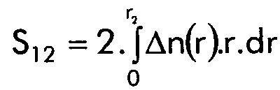
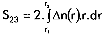
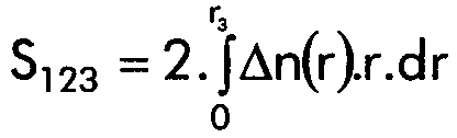
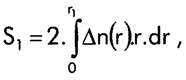
Par ailleurs, on peut choisir avantageusement les paramètres de la fibre selon l'invention de manière à vérifier une ou plusieurs des relations suivantes, dans lesquelles r est le rayon et Δn(r) la différence d'indice entre l'indice au point de rayon r et l'indice de la gaine optique :
- (où r1 est le rayon de la partie centrale), compris entre 45.10-3 et 110.10-3 µm2, et de préférence entre 50.10-3 et 100.10-3µm2.

- (où r2 est le rayon extérieur de la zone intermédiaire), supérieur à 25.10-3 µm2, et de préférence compris entre 30.10-3 et 100.10-3µm2.
- (où r3 est le rayon extérieur de la zone annulaire), compris entre 30.10-3 et 150.10-3 µm2, et de préférence entre 55.10-3 et 140.10-3 µm2.
- inférieur à 220.10-3 µm2, et de préférence compris entre 130.10-3 et 205.10-3 µm2.
- (where r 1 is the radius of the central part), between 45.10 -3 and 110.10 -3 µm 2 , and preferably between 50.10 -3 and 100.10 -3 µm 2 .
- (where r 2 is the outside radius of the intermediate zone), greater than 25.10 -3 µm 2 , and preferably between 30.10 -3 and 100.10 -3 µm 2 .
- (where r 3 is the outside radius of the annular zone), between 30.10 -3 and 150.10 -3 µm 2 , and preferably between 55.10 -3 and 140.10 -3 µm 2 .
- less than 220.10 -3 µm 2 , and preferably between 130.10 -3 and 205.10 -3 µm 2 .
L'invention propose encore un système de transmission à fibre optique à multiplexage en longueurs d'onde, comprenant une telle fibre comme fibre de ligne. Il est alors possible de prévoir en outre de la fibre de compensation de dispersion.The invention also proposes a multiplexing optical fiber transmission system. in wavelengths, including such a fiber as line fiber. It is then possible to additionally provide dispersion compensation fiber.
D'autres caractéristiques et avantages de l'invention apparaítront à la lecture de la description qui suit des modes de réalisation de l'invention, donnés à titre d'exemple et en référence à la figure unique annexée, qui montre une représentation schématique du profil d'indice en échelon avec anneau d'une fibre selon l'invention.Other characteristics and advantages of the invention will appear on reading the description which follows of the embodiments of the invention, given by way of example and in reference to the attached single figure, which shows a schematic representation of the profile of step index with ring of a fiber according to the invention.
Dans tous les modes de réalisation, les rayons r sont donnés en microns (µm) et mesurés par rapport à l'axe de la fibre. Les indices Δn sont mesurés par la différence avec l'indice de la gaine de la fibre.In all the embodiments, the radii r are given in microns (μm) and measured relative to the axis of the fiber. The indices Δn are measured by the difference with the fiber cladding index.
La fibre comprend un coeur optique entouré d'une gaine optique 13. Le profil d'indice du coeur optique est constitué, en partant du centre de la fibre, de :
- une partie centrale 10 en échelon de rayon r1 avec une différence d'indice Δn1 par rapport à la gaine optique 13 sensiblement constante et positive
- un zone intermédiaire 11 qui s'étend jusqu'à un rayon r2, ayant une différence d'indice Δn2 par rapport à la gaine optique 13 sensiblement constante, positive ou négative, et toujours inférieure à Δn1
- une zone annulaire ou anneau 12 qui s'étend jusqu'à un rayon r3, ayant une différence d'indice Δn3 sensiblement constante, positive et inférieure à Δn1.
- a
central portion 10 in echelon of radius r 1 with a difference in index Δn 1 relative to theoptical sheath 13 substantially constant and positive - an intermediate zone 11 which extends to a radius r 2 , having a difference in index Δn 2 relative to the
optical sheath 13 substantially constant, positive or negative, and always less than Δn 1 - an annular zone or
ring 12 which extends to a radius r 3 , having a difference in index Δn 3 substantially constant, positive and less than Δn 1 .
La gaine optique 13 de la fibre s'étend autour de l'anneau 12.The
Le Tableau 1 suivant donne des valeurs possibles de rayons et d'indice pour des
fibres présentant ce type de profil en échelon avec anneau.
Les caractéristiques des fibres selon l'invention permettent une fabrication par des méthodes classiques ; à titre de comparaison, la valeur de différence d'indice de 1% couramment mentionnée dans l'art antérieur correspond à une différence Δn1 égale à 14,5.10-3. On constate que l'invention n'implique pas de forts indices, ni des couches de rayons très faibles, et évite donc des problèmes de fabrication, et également une atténuation excessive de la fibre.The characteristics of the fibers according to the invention allow manufacture by conventional methods; for comparison, the index difference value of 1% commonly mentioned in the prior art corresponds to a difference Δn 1 equal to 14.5.10 -3 . It can be seen that the invention does not imply strong indices or layers of very weak radii, and therefore avoids manufacturing problems, and also excessive attenuation of the fiber.
Les fibres obtenues pour ces valeurs de rayons et d'indices présentent les caractéristiques données dans les lignes correspondantes du Tableau 2 à 1.55 µm, sauf pour les longueurs d'onde de coupure théorique et d'annulation de la dispersion chromatique. Les unités sont les suivantes :
- longueur d'onde de coupure théorique λcth : nm
- longueur d'onde d'annulation de la dispersion chromatique λo : nm
- dispersion chromatique C : ps/(nm.km)
- pente de dispersion chromatique C' : ps/(nm2.km)
- surface effective Seff : µm2
- pertes par courbures PC: dB
- pertes par microcourbures Sµc : néant
- theoretical cut-off wavelength λ cth : nm
- chromatic dispersion cancellation wavelength λ o : nm
- chromatic dispersion C: ps / (nm.km)
- chromatic dispersion slope C ': ps / (nm 2 .km)
- effective area S eff : µm 2
- PC bending losses: dB
- micro- bend losses S µc : none
Les pertes par courbures sont mesurées comme indiqué plus haut par enroulement
de 100 tours de la fibre autour d'un rayon de 30 mm, et par mesure des pertes induites. Les
pertes par microcourbures Sµc sont mesurées par rapport à la fibre ASMF 200 commercialisée
par la demanderesse, et sont sans dimension. Le rapport Seff/C' présente la dimension
µm2.nm2.km/ps.
Dans tous les exemples du Tableau 1, des variations de 5.10-4 des indices Δn1, Δn2 et Δn3 permettent d'obtenir des résultats similaires. Il en est de même des rayons, qui peuvent varier individuellement de 10 % par rapport aux valeurs données tout en obtenant des résultats analogues.In all the examples in Table 1, variations of 5.10 -4 of the indices Δn 1 , Δn 2 and Δn 3 make it possible to obtain similar results. The same applies to the radii, which can vary individually by 10% from the given values while obtaining similar results.
L'invention peut être fabriquée par l'homme du métier à l'aide de techniques connues, comme le MCVD ou les autres techniques couramment utilisées pour la fabrication des fibres optiques.The invention can be manufactured by a person skilled in the art using known techniques, such as MCVD or other techniques commonly used in the manufacture of fibers optical.
La fibre de l'invention peut avantageusement être utilisée comme fibre de ligne dans des systèmes de transmission, et notamment dans des systèmes de transmission à multiplexage en longueurs d'onde pour la plage d'utilisation 1300 nm à 1630 nm. On peut aussi prévoir dans un système utilisant une telle fibre de ligne de la fibre de compensation de dispersion, disposée à intervalles réguliers dans le système, pour limiter l'augmentation de la dispersion chromatique cumulée le long de la ligne de transmission.The fiber of the invention can advantageously be used as line fiber in transmission systems, and in particular in transmission systems using wavelength multiplexing for the range of use 1300 nm to 1630 nm. We can also provide in a system using such a line fiber compensation fiber dispersion, arranged at regular intervals in the system, to limit the increase in cumulative chromatic dispersion along the transmission line.
Bien entendu, la présente invention n'est pas limitée aux exemples et modes de réalisation décrits et représentés, mais elle est susceptible de nombreuses variantes accessibles à l'homme de l'art.Of course, the present invention is not limited to the examples and methods of realization described and represented, but it is susceptible of numerous accessible variants to the skilled person.
Claims (24)
ladite fibre étant caractérisée en ce qu'elle présente en outre les caractéristiques suivantes, pour une longueur d'onde de 1550 nm :
said fiber being characterized in that it also has the following characteristics, for a wavelength of 1550 nm:
Priority Applications (1)
| Application Number | Priority Date | Filing Date | Title |
|---|---|---|---|
| US09/722,059 US6628873B1 (en) | 1999-11-25 | 2000-11-27 | Dispersion shifted fiber for wavelength division multiplex fiber optic transmission systems |
Applications Claiming Priority (2)
| Application Number | Priority Date | Filing Date | Title |
|---|---|---|---|
| FR9914829 | 1999-11-25 | ||
| FR9914829A FR2801685B1 (en) | 1999-11-25 | 1999-11-25 | OPTICAL FIBER WITH OFFSET CHROMATIC DISPERSION FOR WAVELENGTH MULTIPLEXED FIBER OPTIC TRANSMISSION SYSTEMS |
Publications (2)
| Publication Number | Publication Date |
|---|---|
| EP1103830A1 true EP1103830A1 (en) | 2001-05-30 |
| EP1103830B1 EP1103830B1 (en) | 2007-03-07 |
Family
ID=9552526
Family Applications (1)
| Application Number | Title | Priority Date | Filing Date |
|---|---|---|---|
| EP00403301A Expired - Lifetime EP1103830B1 (en) | 1999-11-25 | 2000-11-24 | Dispersion-shifted optical fibre for wavelength dividion multipexing optical fiber transmission systems |
Country Status (7)
| Country | Link |
|---|---|
| US (1) | US6612756B1 (en) |
| EP (1) | EP1103830B1 (en) |
| CN (1) | CN1323504C (en) |
| AT (1) | ATE356361T1 (en) |
| DE (1) | DE60033765T2 (en) |
| DK (1) | DK1103830T3 (en) |
| FR (1) | FR2801685B1 (en) |
Cited By (3)
| Publication number | Priority date | Publication date | Assignee | Title |
|---|---|---|---|---|
| US6647191B2 (en) | 2000-08-16 | 2003-11-11 | Corning Incorporated | Optical fiber with large effective area, low dispersion and low dispersion slope |
| US6701053B2 (en) | 1999-11-22 | 2004-03-02 | Corning Incorporated | Dispersion shifted large effective area waveguide fiber |
| FR2849213A1 (en) * | 2002-12-24 | 2004-06-25 | Cit Alcatel | Optical fiber for transmission of wavelength division multiplexing, has core presenting variable index profile than sheath of constant index, and buried section of minimum index with index lower than sheath index |
Families Citing this family (6)
| Publication number | Priority date | Publication date | Assignee | Title |
|---|---|---|---|---|
| WO2004011975A1 (en) * | 2002-07-31 | 2004-02-05 | Corning Incorporated | Non-zero dispersion shifted optical fiber having large effective area, low slope and low zero dispersion |
| CN1310045C (en) * | 2002-10-01 | 2007-04-11 | 古河电气工业株式会社 | Optical fibre, optical transmission line and maufacturing method of optical fibre |
| JP2004126141A (en) * | 2002-10-01 | 2004-04-22 | Furukawa Electric Co Ltd:The | Optical fiber and its manufacturing method |
| US6985662B2 (en) * | 2003-10-30 | 2006-01-10 | Corning Incorporated | Dispersion compensating fiber for moderate dispersion NZDSF and transmission system utilizing same |
| US7024083B2 (en) * | 2004-02-20 | 2006-04-04 | Corning Incorporated | Non-zero dispersion shifted optical fiber |
| US7106934B1 (en) | 2005-06-30 | 2006-09-12 | Corning Incorporated | Non-zero dispersion shifted optical fiber |
Citations (4)
| Publication number | Priority date | Publication date | Assignee | Title |
|---|---|---|---|---|
| EP0668520A2 (en) * | 1994-02-16 | 1995-08-23 | AT&T Corp. | Article comprising a dispersion-compensating optical waveguide |
| US5838867A (en) * | 1996-04-15 | 1998-11-17 | Sumitomo Electric Industries, Ltd. | Dispersion compensating fiber and optical transmission system including the same |
| EP0883002A1 (en) * | 1997-06-05 | 1998-12-09 | Lucent Technologies Inc. | Optical fiber having a low-dispersion slope in the erbium amplifier wavelength region |
| EP0938018A1 (en) * | 1997-08-27 | 1999-08-25 | Sumitomo Electric Industries, Ltd. | Non-linear optical fiber, optical fiber coil, and wavelength converter |
Family Cites Families (9)
| Publication number | Priority date | Publication date | Assignee | Title |
|---|---|---|---|---|
| US4447125A (en) * | 1981-06-09 | 1984-05-08 | Bell Telephone Laboratories, Incorporated | Low dispension single mode fiber |
| FR2724234B1 (en) * | 1994-09-05 | 1997-01-03 | Alcatel Fibres Optiques | SINGLE-MODE OPTICAL FIBER WITH OFFSET DISPERSION |
| JPH09304640A (en) * | 1996-02-12 | 1997-11-28 | Corning Inc | Single-mode optical waveguide with large effective area |
| JP3418086B2 (en) * | 1997-05-09 | 2003-06-16 | 住友電気工業株式会社 | Optical transmission line for wavelength division multiplexing transmission and method of configuring the same |
| CA2267252A1 (en) * | 1997-08-28 | 1999-02-28 | Sumitomo Electric Industries, Ltd. | Dispersion-shift fiber |
| KR19990038607A (en) * | 1997-11-06 | 1999-06-05 | 윤종용 | Singlemode Fiber with Multilevel Core Structure |
| US6337942B1 (en) * | 1998-12-17 | 2002-01-08 | Sumitomo Electric Industries, Ltd. | Optical fiber |
| US6243522B1 (en) * | 1998-12-21 | 2001-06-05 | Corning Incorporated | Photonic crystal fiber |
| FR2795828B1 (en) * | 1999-06-29 | 2001-10-05 | Cit Alcatel | OPTICAL FIBER FOR THE COMPENSATION OF THE CHROMATIC DISPERSION OF A POSITIVE CHROMATIC DISPERSION OPTICAL FIBER |
-
1999
- 1999-11-25 FR FR9914829A patent/FR2801685B1/en not_active Expired - Fee Related
- 1999-12-23 US US09/471,025 patent/US6612756B1/en not_active Expired - Lifetime
-
2000
- 2000-11-24 AT AT00403301T patent/ATE356361T1/en not_active IP Right Cessation
- 2000-11-24 DE DE60033765T patent/DE60033765T2/en not_active Expired - Lifetime
- 2000-11-24 EP EP00403301A patent/EP1103830B1/en not_active Expired - Lifetime
- 2000-11-24 DK DK00403301T patent/DK1103830T3/en active
- 2000-11-24 CN CNB001380494A patent/CN1323504C/en not_active Expired - Lifetime
Patent Citations (4)
| Publication number | Priority date | Publication date | Assignee | Title |
|---|---|---|---|---|
| EP0668520A2 (en) * | 1994-02-16 | 1995-08-23 | AT&T Corp. | Article comprising a dispersion-compensating optical waveguide |
| US5838867A (en) * | 1996-04-15 | 1998-11-17 | Sumitomo Electric Industries, Ltd. | Dispersion compensating fiber and optical transmission system including the same |
| EP0883002A1 (en) * | 1997-06-05 | 1998-12-09 | Lucent Technologies Inc. | Optical fiber having a low-dispersion slope in the erbium amplifier wavelength region |
| EP0938018A1 (en) * | 1997-08-27 | 1999-08-25 | Sumitomo Electric Industries, Ltd. | Non-linear optical fiber, optical fiber coil, and wavelength converter |
Cited By (7)
| Publication number | Priority date | Publication date | Assignee | Title |
|---|---|---|---|---|
| US6701053B2 (en) | 1999-11-22 | 2004-03-02 | Corning Incorporated | Dispersion shifted large effective area waveguide fiber |
| US6647191B2 (en) | 2000-08-16 | 2003-11-11 | Corning Incorporated | Optical fiber with large effective area, low dispersion and low dispersion slope |
| FR2849213A1 (en) * | 2002-12-24 | 2004-06-25 | Cit Alcatel | Optical fiber for transmission of wavelength division multiplexing, has core presenting variable index profile than sheath of constant index, and buried section of minimum index with index lower than sheath index |
| EP1434070A1 (en) * | 2002-12-24 | 2004-06-30 | Alcatel | Monomode optical fiber with optimized chromatic dispersion |
| US6895153B2 (en) | 2002-12-24 | 2005-05-17 | Alcatel | Optical fiber for wavelength division multiplex transmission networks |
| EP1655626A1 (en) * | 2002-12-24 | 2006-05-10 | Draka Comteq B.V. | Optical monomode fibre with optimised chromatic dispersion |
| CN100395570C (en) * | 2002-12-24 | 2008-06-18 | 阿尔卡特公司 | Optical fibre |
Also Published As
| Publication number | Publication date |
|---|---|
| DK1103830T3 (en) | 2007-04-30 |
| FR2801685B1 (en) | 2002-02-22 |
| US6612756B1 (en) | 2003-09-02 |
| DE60033765D1 (en) | 2007-04-19 |
| EP1103830B1 (en) | 2007-03-07 |
| CN1303194A (en) | 2001-07-11 |
| DE60033765T2 (en) | 2007-11-22 |
| FR2801685A1 (en) | 2001-06-01 |
| ATE356361T1 (en) | 2007-03-15 |
| CN1323504C (en) | 2007-06-27 |
Similar Documents
| Publication | Publication Date | Title |
|---|---|---|
| EP1067412B1 (en) | Dispersion compensating optical fiber | |
| EP1288685A1 (en) | Optical fibre for a wavelength division multiplexing transmission system | |
| EP1046069A1 (en) | Optical fibre with optimised ratio of effective area to dispersion scope for optical fibre transmission system with wavelength multiplexing | |
| FR2941541A1 (en) | OPTICAL FIBER MONOMODE | |
| EP1030199A1 (en) | Line fiber for WDM optical fiber transmission systems | |
| FR2953606A1 (en) | MULTIMODE OPTICAL FIBER WITH BROAD BANDWIDTH AND LOW BENDBACK LOSSES | |
| FR2941540A1 (en) | MONOMODE OPTICAL FIBER HAVING ENHANCED EFFECTIVE SURFACE | |
| EP1081514B1 (en) | Optical fibre for compensating the chromatic dispersion of a positive chromatic dispersion optical fibre | |
| EP0987569B1 (en) | High rate optimised monomode dispersion-shifted optical fiber | |
| EP1128196B1 (en) | Monomode optical fiber cable for WDM optical fiber transmission net | |
| EP1217399A1 (en) | Optical fiber for chromatic dispersion compensation of a NZ-DSF-fiber with positive chromatic dispersion | |
| EP1103830A1 (en) | Dispersion-shifted optical fibre for wavelength dividion multipexing optical fiber transmission systems | |
| EP1018656B1 (en) | Optical fibre with low slope of chromatic dispersion | |
| EP1202087B1 (en) | S-band chromatic dispersion compensating fiber | |
| EP1213595B1 (en) | Chromatic dispersion compensation in a fiber transmission system and compensation fiber | |
| EP1202088A1 (en) | Dispersion compensating fiber for the compensation of an optical fiber transmission line with positive chromatical dispersion | |
| EP0992818A1 (en) | Dispersion shifted optical fiber with positive dispersion at 1550 nm | |
| EP1030200A1 (en) | Optical fibre with large effective area and strong chromatic dispersion | |
| EP1312950B1 (en) | Chromatic dispersion compensating fibre for fibre optic transmission system in U band | |
| EP1288682B1 (en) | Optical fiber for wavelength division multiplexing system | |
| EP1018812B1 (en) | Optical fiber WDM transmission system with chromatic dispersion compensation |
Legal Events
| Date | Code | Title | Description |
|---|---|---|---|
| PUAI | Public reference made under article 153(3) epc to a published international application that has entered the european phase |
Free format text: ORIGINAL CODE: 0009012 |
|
| AK | Designated contracting states |
Kind code of ref document: A1 Designated state(s): AT BE CH CY DE DK ES FI FR GB GR IE IT LI LU MC NL PT SE TR |
|
| AX | Request for extension of the european patent |
Free format text: AL;LT;LV;MK;RO;SI |
|
| 17P | Request for examination filed |
Effective date: 20011130 |
|
| AKX | Designation fees paid |
Free format text: AT BE CH CY DE DK ES FI FR GB GR IE IT LI LU MC NL PT SE TR |
|
| RAP1 | Party data changed (applicant data changed or rights of an application transferred) |
Owner name: DRAKA COMTEQ B.V. |
|
| 17Q | First examination report despatched |
Effective date: 20050428 |
|
| GRAP | Despatch of communication of intention to grant a patent |
Free format text: ORIGINAL CODE: EPIDOSNIGR1 |
|
| RIC1 | Information provided on ipc code assigned before grant |
Ipc: G02B 6/02 20060101AFI20061030BHEP |
|
| GRAS | Grant fee paid |
Free format text: ORIGINAL CODE: EPIDOSNIGR3 |
|
| GRAA | (expected) grant |
Free format text: ORIGINAL CODE: 0009210 |
|
| AK | Designated contracting states |
Kind code of ref document: B1 Designated state(s): AT BE CH CY DE DK ES FI FR GB GR IE IT LI LU MC NL PT SE TR |
|
| PG25 | Lapsed in a contracting state [announced via postgrant information from national office to epo] |
Ref country code: AT Free format text: LAPSE BECAUSE OF FAILURE TO SUBMIT A TRANSLATION OF THE DESCRIPTION OR TO PAY THE FEE WITHIN THE PRESCRIBED TIME-LIMIT Effective date: 20070307 Ref country code: FI Free format text: LAPSE BECAUSE OF FAILURE TO SUBMIT A TRANSLATION OF THE DESCRIPTION OR TO PAY THE FEE WITHIN THE PRESCRIBED TIME-LIMIT Effective date: 20070307 Ref country code: NL Free format text: LAPSE BECAUSE OF FAILURE TO SUBMIT A TRANSLATION OF THE DESCRIPTION OR TO PAY THE FEE WITHIN THE PRESCRIBED TIME-LIMIT Effective date: 20070307 Ref country code: IE Free format text: LAPSE BECAUSE OF FAILURE TO SUBMIT A TRANSLATION OF THE DESCRIPTION OR TO PAY THE FEE WITHIN THE PRESCRIBED TIME-LIMIT Effective date: 20070307 |
|
| REG | Reference to a national code |
Ref country code: GB Ref legal event code: FG4D Free format text: NOT ENGLISH |
|
| REG | Reference to a national code |
Ref country code: CH Ref legal event code: EP |
|
| REF | Corresponds to: |
Ref document number: 60033765 Country of ref document: DE Date of ref document: 20070419 Kind code of ref document: P |
|
| REG | Reference to a national code |
Ref country code: DK Ref legal event code: T3 |
|
| REG | Reference to a national code |
Ref country code: IE Ref legal event code: FG4D Free format text: LANGUAGE OF EP DOCUMENT: FRENCH |
|
| GBT | Gb: translation of ep patent filed (gb section 77(6)(a)/1977) |
Effective date: 20070510 |
|
| PG25 | Lapsed in a contracting state [announced via postgrant information from national office to epo] |
Ref country code: SE Free format text: LAPSE BECAUSE OF FAILURE TO SUBMIT A TRANSLATION OF THE DESCRIPTION OR TO PAY THE FEE WITHIN THE PRESCRIBED TIME-LIMIT Effective date: 20070607 |
|
| RAP2 | Party data changed (patent owner data changed or rights of a patent transferred) |
Owner name: DRAKA COMTEQ B.V. |
|
| PG25 | Lapsed in a contracting state [announced via postgrant information from national office to epo] |
Ref country code: ES Free format text: LAPSE BECAUSE OF FAILURE TO SUBMIT A TRANSLATION OF THE DESCRIPTION OR TO PAY THE FEE WITHIN THE PRESCRIBED TIME-LIMIT Effective date: 20070618 |
|
| RAP2 | Party data changed (patent owner data changed or rights of a patent transferred) |
Owner name: DRAKA COMTEQ B.V. |
|
| NLT2 | Nl: modifications (of names), taken from the european patent patent bulletin |
Owner name: DRAKA COMTEQ B.V. Effective date: 20070613 |
|
| PG25 | Lapsed in a contracting state [announced via postgrant information from national office to epo] |
Ref country code: PT Free format text: LAPSE BECAUSE OF FAILURE TO SUBMIT A TRANSLATION OF THE DESCRIPTION OR TO PAY THE FEE WITHIN THE PRESCRIBED TIME-LIMIT Effective date: 20070807 |
|
| NLV1 | Nl: lapsed or annulled due to failure to fulfill the requirements of art. 29p and 29m of the patents act | ||
| REG | Reference to a national code |
Ref country code: IE Ref legal event code: FD4D |
|
| PLBE | No opposition filed within time limit |
Free format text: ORIGINAL CODE: 0009261 |
|
| STAA | Information on the status of an ep patent application or granted ep patent |
Free format text: STATUS: NO OPPOSITION FILED WITHIN TIME LIMIT |
|
| 26N | No opposition filed |
Effective date: 20071210 |
|
| PG25 | Lapsed in a contracting state [announced via postgrant information from national office to epo] |
Ref country code: GR Free format text: LAPSE BECAUSE OF FAILURE TO SUBMIT A TRANSLATION OF THE DESCRIPTION OR TO PAY THE FEE WITHIN THE PRESCRIBED TIME-LIMIT Effective date: 20070608 |
|
| BERE | Be: lapsed |
Owner name: DRAKA COMTEQ B.V. Effective date: 20071130 |
|
| PG25 | Lapsed in a contracting state [announced via postgrant information from national office to epo] |
Ref country code: MC Free format text: LAPSE BECAUSE OF NON-PAYMENT OF DUE FEES Effective date: 20071130 |
|
| PG25 | Lapsed in a contracting state [announced via postgrant information from national office to epo] |
Ref country code: LI Free format text: LAPSE BECAUSE OF NON-PAYMENT OF DUE FEES Effective date: 20071130 Ref country code: CH Free format text: LAPSE BECAUSE OF NON-PAYMENT OF DUE FEES Effective date: 20071130 |
|
| REG | Reference to a national code |
Ref country code: CH Ref legal event code: PL |
|
| PG25 | Lapsed in a contracting state [announced via postgrant information from national office to epo] |
Ref country code: BE Free format text: LAPSE BECAUSE OF NON-PAYMENT OF DUE FEES Effective date: 20071130 |
|
| PG25 | Lapsed in a contracting state [announced via postgrant information from national office to epo] |
Ref country code: CY Free format text: LAPSE BECAUSE OF FAILURE TO SUBMIT A TRANSLATION OF THE DESCRIPTION OR TO PAY THE FEE WITHIN THE PRESCRIBED TIME-LIMIT Effective date: 20070307 |
|
| PG25 | Lapsed in a contracting state [announced via postgrant information from national office to epo] |
Ref country code: LU Free format text: LAPSE BECAUSE OF NON-PAYMENT OF DUE FEES Effective date: 20071124 |
|
| PG25 | Lapsed in a contracting state [announced via postgrant information from national office to epo] |
Ref country code: TR Free format text: LAPSE BECAUSE OF FAILURE TO SUBMIT A TRANSLATION OF THE DESCRIPTION OR TO PAY THE FEE WITHIN THE PRESCRIBED TIME-LIMIT Effective date: 20070307 |
|
| REG | Reference to a national code |
Ref country code: FR Ref legal event code: PLFP Year of fee payment: 16 |
|
| REG | Reference to a national code |
Ref country code: FR Ref legal event code: PLFP Year of fee payment: 17 |
|
| REG | Reference to a national code |
Ref country code: FR Ref legal event code: PLFP Year of fee payment: 18 |
|
| PGFP | Annual fee paid to national office [announced via postgrant information from national office to epo] |
Ref country code: DE Payment date: 20191127 Year of fee payment: 20 |
|
| PGFP | Annual fee paid to national office [announced via postgrant information from national office to epo] |
Ref country code: FR Payment date: 20191125 Year of fee payment: 20 Ref country code: DK Payment date: 20191127 Year of fee payment: 20 Ref country code: IT Payment date: 20191125 Year of fee payment: 20 |
|
| PGFP | Annual fee paid to national office [announced via postgrant information from national office to epo] |
Ref country code: GB Payment date: 20191127 Year of fee payment: 20 |
|
| REG | Reference to a national code |
Ref country code: DE Ref legal event code: R071 Ref document number: 60033765 Country of ref document: DE |
|
| REG | Reference to a national code |
Ref country code: DK Ref legal event code: EUP Expiry date: 20201124 |
|
| REG | Reference to a national code |
Ref country code: GB Ref legal event code: PE20 Expiry date: 20201123 |
|
| PG25 | Lapsed in a contracting state [announced via postgrant information from national office to epo] |
Ref country code: GB Free format text: LAPSE BECAUSE OF EXPIRATION OF PROTECTION Effective date: 20201123 |