EP1103805A2 - Ultraviolet light permeable filter for flaw detection apparatus and method for detection of flaws - Google Patents
Ultraviolet light permeable filter for flaw detection apparatus and method for detection of flaws Download PDFInfo
- Publication number
- EP1103805A2 EP1103805A2 EP00307025A EP00307025A EP1103805A2 EP 1103805 A2 EP1103805 A2 EP 1103805A2 EP 00307025 A EP00307025 A EP 00307025A EP 00307025 A EP00307025 A EP 00307025A EP 1103805 A2 EP1103805 A2 EP 1103805A2
- Authority
- EP
- European Patent Office
- Prior art keywords
- filter
- ultraviolet light
- layer
- light permeable
- permeable filter
- Prior art date
- Legal status (The legal status is an assumption and is not a legal conclusion. Google has not performed a legal analysis and makes no representation as to the accuracy of the status listed.)
- Granted
Links
Images





Classifications
-
- G—PHYSICS
- G02—OPTICS
- G02B—OPTICAL ELEMENTS, SYSTEMS OR APPARATUS
- G02B5/00—Optical elements other than lenses
- G02B5/20—Filters
-
- G—PHYSICS
- G02—OPTICS
- G02B—OPTICAL ELEMENTS, SYSTEMS OR APPARATUS
- G02B5/00—Optical elements other than lenses
- G02B5/20—Filters
- G02B5/208—Filters for use with infrared or ultraviolet radiation, e.g. for separating visible light from infrared and/or ultraviolet radiation
-
- G—PHYSICS
- G01—MEASURING; TESTING
- G01N—INVESTIGATING OR ANALYSING MATERIALS BY DETERMINING THEIR CHEMICAL OR PHYSICAL PROPERTIES
- G01N21/00—Investigating or analysing materials by the use of optical means, i.e. using sub-millimetre waves, infrared, visible or ultraviolet light
- G01N21/84—Systems specially adapted for particular applications
- G01N21/88—Investigating the presence of flaws or contamination
- G01N21/91—Investigating the presence of flaws or contamination using penetration of dyes, e.g. fluorescent ink
-
- G—PHYSICS
- G02—OPTICS
- G02B—OPTICAL ELEMENTS, SYSTEMS OR APPARATUS
- G02B5/00—Optical elements other than lenses
- G02B5/20—Filters
- G02B5/28—Interference filters
- G02B5/283—Interference filters designed for the ultraviolet
Definitions
- the present invention relates to an ultraviolet light permeable filter for a flaw detection apparatus and a method for the detection of flaws.
- an ultraviolet detection light source also called a "black” light by those skilled in the art
- light is emitted from a metal halide lamp and is passed through an ultraviolet light permeable filter so that the fluorescent penetrant liquid (or fluorescent magnetic powder) is excited to emit radiation.
- an ultraviolet flaw detection apparatus comprising the metal halide lamp and an ultraviolet light permeable filter having a minimum wavelength of 385 ⁇ 5 nm which can be recognised with normal eyesight is provided.
- An inspector can reduce fatigue or avoid mistakes caused by fatigue from the blue-violet radiation by using a wavelength below 400 nm.
- the present inventor has done research and experiments to provide an ultraviolet light permeable filter which prevents the occurrence of halation, especially reddish halation which is the main cause of overlooking a flaw during inspection.
- this inventor has confirmed that visible radiation in the wavelength ranges of 380 nm to 410 nm and 694 nm to 780 nm passes through a known ultraviolet light permeable filter.
- This prior art filter is used with various kinds of ultraviolet flaw detection light sources composed of metal halide lamps.
- the radiation in the above ranges reflects on the test display to produce a reddish halation.
- the inventor has found that the reddish halation is avoided when the radiation in the wavelength range of 694 nm to 780 nm does not pass through the filter.
- This invention provides a filter device comprising a dielectric multi-film layer which is formed, in use, on the surface of an ultraviolet light permeable filter, wherein visible radiation in the range of 694 nm to 780 nm is reflected by the filter and does not pass therethrough.
- the invention also provides a device comprising a filter where the dielectric multi-film layer is composed in a stack in which layers of relatively low refractivity material alternate with layers of relatively high refractivity material.
- This invention further provides a device of any filter as mentioned so far where the multi-film layer comprises a layer of relatively high refractivity material which is sandwiched between layers of relatively low refractivity material and the obtained composite is a plurality of layers thick.
- the invention resides in any flaw detection light source equipped with any of said filters of the present invention.
- FIG.1 is a partial diagrammatic longitudinal section of a first embodiment of an ultraviolet light permeable filter according to the present invention.
- FIG.2 shows part of the filter of Fig 1 in greater detail.
- FIG.3 shows part of the filter of Fig 1 in still greater detail.
- FIG.4 is a partial diagrammatic longitudinal section of a second embodiment of an ultraviolet light permeable filter according to the present invention.
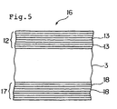
- FIG.5 shows part of the filter of Fig 4 in greater detail.
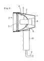
- FIG.6 is a partially schematic side view of a prior art flaw detection apparatus.
- FIG.7 is a spectrophotometric curve of light permeability against wavelength for a known halide lamp with no filter equipped.
- FIG.8 is a spectrophotometric curve of light permeability against wavelength for the same halide lamp as Fig 7, equipped with a prior ultraviolet light permeable filter.
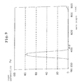
- FIGS.9 to 11 are spectrophotometric curves of light permeability against wavelength for the same halide lamp of Fig 7 equipped with different filters according to the present invention.
- the apparatus comprises a lamp housing in the form of a metal shell (1) having an opening (2) on one side for permitting the passage of light therethrough in use, an uncoated glass filter (3), a concave reflector mirror (5) having an anodised mirror face (4) and a metal halide lamp (7).
- the lamp (7) is mounted on a socket (8) at an opposite side of the housing to the opening (2).
- the reflector mirror (5) has a hole drilled through its centre and is mounted in the housing such that the lamp (7) projects through the hole (6) and in such a manner that in use, light emitted from the lamp (7) reflects off the anodised mirror face (4) and is directed towards the opening (2).
- the filter (3) is mounted in the housing adjacent the opening (2) such that light from the lamp (7) passes through the filter (3) before leaving the housing.
- Power for the lamp is provided by a binary power supply cord (9) which is connected to an inverter (not shown) externally of the metal shell (1).
- the apparatus also includes a handle (10) through which the cord (9) passes.
- the lamp (7) is marketed under the name "70W/FDA” by Marktec Corporation.
- the filter (3) is marketed under the name "D10FA", also by Marktec Corporation.
- Fig 7 is a spectrophotometric curve of light permeability (%) plotted against wavelength (nm) for the 70W/FDA lamp.
- Fig 8 is a similar spectrophotometric curve for the same lamp fitted with the D10FA filter.
- this prior art filter absorbs visible radiation in the wavelength region of from 413 nm to 694 nm, whereas radiation in a wavelength range of from 380 nm to 413 nm and 694 nm to 780 nm penetrates therethrough (the spectrophotometric curves were obtained using a special spectrophotometer developed and supplied by Shimadzu Seisakusho Co., Ltd., model No. U-2200).
- a prior art flaw detection light source was equipped with an ultraviolet light permeable glass filter and a fluorescent magnetic powder test was performed. As a result, a pale blue halation could not be observed, but a reddish halation was observed, which caused overlooking of the indicated scratch.
- the filter which causes the visible radiation over the wavelength of 700 nm to reflect and which has the spectrophotometric curve of FIG.9 was equipped to a flaw detection apparatus and the fluorescent magnetic powder test was performed. As a result, the pale blue halation was observed while the reddish halation was not observed. The indicated scratch was clearly observed.
- the filter which causes the visible radiation in the wavelengths of 400 nm to 410 nm and over about 700 nm to reflect and which has the spectrophotometric of the curve of FIG. 10 was equipped to a flaw detection apparatus and the fluorescent magnetic powder test was performed. As a result, the pale blue halation was observed to a small extent while the reddish halation was not observed. As with the second test, the indicated scratch was clearly observed.
- the inventor realised that the radiation in the wavelength of about 700 nm is observed as a reddish halation and that the occurrence of this halation was the true source of an inspector's mistake. Therefore, the inventor has developed an ultraviolet light permeable filter which causes the radiation to reflect and not to penetrate in a wavelength range from about 700 nm to 780 nm. When this filter is equipped to a flaw detection apparatus, the satisfactory result has been confirmed.
- Fig 1 is a partial diagrammatic longitudinal section of an ultraviolet light permeable filter (11) for use in a flaw detection apparatus.
- the filter (11) comprises a glass substrate (3) with a dielectric multi-film layer (12) coated thereon.
- Fig 2 shows the layer (12) in more detail.
- the layer (12) consists of a plurality of composite layers (13), each composite layer (13) being composed of three individual layers (14) and (15).
- the individual layers which comprise the composite layer (13) consist of a high refractivity material (15) sandwiched between two layers of a low refractivity material (14).
- the expressions "high” and "low” used to describe the refractivity of the individual materials of a composite layer are relative not absolute, i.e.
- the "high" refractivity material has a high refractivity relative to the low refractivity material and vice versa.
- eight such composite layers (13) are provided on the glass substrate (3).
- the filter (11) so formed reflects visible radiation in a wavelength range of from 694 nm to 780 nm.
- the dielectric multi-film layer (12) may be formed by coating individual thin layers by vapour deposition, such as a vacuum evaporation method or an ion plating method so that the wavelength range which can pass through the filter is selectively controlled.
- vapour deposition methods are relatively inexpensive.
- Suitable examples of materials for the high refractivity layers are hafnium oxide (HfO 2 ), titanium oxide (TiO 2 ), zirconium oxide (ZrO 2 ) and zinc sulphide (ZnS).
- Examples of materials suitable for the low refractivity layers are silicon oxide (SiO 2 ), magnesium fluoride (MgF 2 ) and cryolite (Na 8 AlF 6 ).
- a multi-film dielectric layer 12 is formed by vacuum thin film evaporation treatment using an automatic successive vacuum thin film forming machine (CES-3 supplied by Kabushiki Kaisha Synchron).
- the first layer (14) to be coated is silicon oxide material having a low refractivity (layer thickness 146 nm) upon which is subsequently coated a titanium oxide layer having a high refractivity (layer thickness 520 nm).
- a further layer (14) of the same low refractivity silicon oxide material (thickness 146 nm) is coated thereon to give a composite layer (13) comprising a high refractivity layer (15) sandwiched between two low refractivity layers (14).
- the ultraviolet light permeable filter (11) obtained is as shown in Figs 1 to 3.
- the spectrophotometric curve for the filter (11) is as shown in Fig 9, with visible radiation of wavelengths 694 to 780 reflecting on the filter and not passing therethrough.
- the filter (11) so obtained was then equipped to a flaw detection apparatus (super light D-10 supplied by Marktec Corporation having a metal halide lamp 70W-FDA).
- the apparatus was tested under the following conditions:
- each composite layer (13) may comprise a low refractivity material sandwiched between two high refractivity materials.
- each composite layer (13) may consist of only a low refractivity material and a high refractivity material, with either the high refractivity or low refractivity material being the first layer on the glass substrate (3).
- FIGs 4 and 5 a second embodiment of an ultraviolet light permeable filter (16) in accordance with the present invention is shown.
- the glass substrate (3) is coated on one side with eight composite layers (13) which are as described with reference to Figs 1 to 3.
- the opposite side of the glass substrate (3) is coated with a multi-film layer (17) having eight composite layers (18).
- Each composite layer (18) comprises a layer of high refractivity material sandwiched between two layers of low refractivity material.
- the composition of the layers (18) is chosen such that visible radiation at wavelengths of from 400 nm to 410 nm is reflected and does not pass through the multi-film layer (17).
- the filter (11) of Example 1 was coated on its uncoated side with a multi-film layer (17).
- the multi-film layer (17) was produced by the same vacuum thin film evaporation method as described with reference to Example 1.
- Each composite layer (18) comprises a layer of high refractivity titanium oxide material (layer thickness 325 nm) sandwiched between layers of a low refractivity silicon oxide material (each layer thickness 91 nm). Eight such composite layers (18) were formed.
- the resultant filter (16) exhibited a spectrophotometric curve as shown in Fig 11, which confirms that visible radiation having a wavelength of between 405 nm and 410 nm is reflected by the filter (16) and does not penetrate therethrough.
- the filter (16) was tested in a flaw detection method in the manner described with reference to Example 1. No halation was present and there was good observation of the indicated scratch.
- a filter is coated on one side in the same manner as Example 1 to give the same general layer structure.
- the only difference being that the low refractivity material used was magnesium fluoride (layer thickness 138 nm) and the high refractivity material used was hafnium oxide (layer thickness 440 nm).
- the filter so obtained gave a similar spectrophotometric curve to that shown in Fig 9 for Example 1 (i.e. visible radiation in the wavelengths of from 694 nm to 780 nm was reflected by the filter and did not penetrate therethrough).
- a flaw detection test in the same manner as described with reference to Example 1, blue halation was observed but reddish halation was not. As a result, the indicated scratch was clearly observed.
- a filter was formed having the same general layer structures as Example 2.
- the multi-film layer (12) on one side of the filter substrate was the same as that of Example 3 (each composite layer (13) consisting of a hafnium oxide layer (440 nm thick) sandwiched between two magnesium fluoride layers (each 138 nm thick)).
- each composite layer (18) of the second multi-film layer (17) was formed of a layer of high refractivity titanium oxide (layer thickness 325 nm) sandwiched between two low refractivity magnesium fluoride layers (each layer thickness 138 nm).
- an ultraviolet light permeable filter having the structure shown in Figs 4 and 5 was obtained.
- the spectrophotometric curve was similar to that shown in Fig 11 (i.e. visible radiation of wavelengths from 405 to 410 nm was reflected by the filter and not able to penetrate therethrough).
- a flaw detection method in the name manner as Example 1 no halation at all was observed and the indicated scratch was clearly observed under inspection.
- the present invention provides an ultraviolet light permeable filter for a flaw detection apparatus, the filter reflecting visible radiation in the wavelength range from 694 nm to 780 nm thereby preventing penetration of radiation in that wavelength through the filter.
- the flaws and scratches can be promptly and easily found by inspectors even on plane surfaces and well polished or well finished faces which can be very difficult using the prior art filters.
Landscapes
- Physics & Mathematics (AREA)
- General Physics & Mathematics (AREA)
- Optics & Photonics (AREA)
- Health & Medical Sciences (AREA)
- Immunology (AREA)
- Toxicology (AREA)
- General Health & Medical Sciences (AREA)
- Analytical Chemistry (AREA)
- Chemical & Material Sciences (AREA)
- Pathology (AREA)
- Life Sciences & Earth Sciences (AREA)
- Biochemistry (AREA)
- Spectrometry And Color Measurement (AREA)
- Investigating Materials By The Use Of Optical Means Adapted For Particular Applications (AREA)
- Investigating Or Analysing Materials By Optical Means (AREA)
- Optical Filters (AREA)
- Investigating, Analyzing Materials By Fluorescence Or Luminescence (AREA)
- Surface Treatment Of Glass (AREA)
Abstract
Description
Claims (11)
- An ultraviolet light permeable filter for use in an ultraviolet flaw detection apparatus comprises a glass substrate having a dielectric coating on at least one surface thereof which reflects visible radiation in a wavelength range from 694 nm to 780 nm and prevents penetration of radiation of said wavelength range through the filter.
- An ultraviolet light permeable filter according to Claim 1, wherein the or each dielectric coating is composed of a plurality of composite layers.
- An ultraviolet light permeable filter as claimed in Claim 2, wherein the or each composite layer comprises one layer of relatively low refractivity material and one layer of relatively high refractivity material.
- An ultraviolet light permeable filter as claimed in Claim 2, wherein the or each composite layer comprises a layer of relatively high refractivity material sandwiched between two layers of relatively low refractivity material or a layer of relatively low refractivity material sandwiched between two layers of relatively high refractivity material.
- An ultraviolet light permeable filter as claimed in Claim 3 or Claim 4, wherein said relatively low refractivity material is selected from silicon oxide, magnesium fluoride and cryolite (Na8AlF6).
- An ultraviolet light permeable filter as claimed in any one of Claims 3 to 5, wherein said relatively high refractivity material is selected from hafnium oxide, titanium oxide, zirconium oxide and zinc sulphide.
- A flaw detection apparatus comprising an ultraviolet light source and a filter in accordance with any one Claims 1 to 6.
- A method of flaw detection on a surface comprising the steps of:(i) applying a fluorescent material to said surface(ii) irradiating said surface with an ultraviolet light source which has a visible frequency wherein wavelengths from 694 nm to 780 nm are eliminated, and(iii) viewing said surface whereby any defects are visible at a wavelength of from 380 nm to 410 nm.
- The method as claimed in Claim 8, wherein step (i) is achieved using a magnetic powder in a dispersing agent and said method includes an additional step of subjecting the surface to magnetisation before or during step (iii).
- The method as claimed in Claim 8 or Claim 9, wherein the wavelengths of from 694 nm to 780 nm are eliminated by passing light from said light source through a filter in accordance with any one of Claims 1 to 6.
- A multi-layer dielectric coating adapted and constructed for application to a glass substrate whereby to form, when so applied, an ultraviolet light permeable filter in accordance with any one of claims 1 to 6.
Applications Claiming Priority (2)
| Application Number | Priority Date | Filing Date | Title |
|---|---|---|---|
| JP33804199 | 1999-11-29 | ||
| JP33804199A JP2001154016A (en) | 1999-11-29 | 1999-11-29 | Ultraviolet transmission filter and ultraviolet inspection lamp using the ultraviolet transmission filter |
Publications (3)
| Publication Number | Publication Date |
|---|---|
| EP1103805A2 true EP1103805A2 (en) | 2001-05-30 |
| EP1103805A3 EP1103805A3 (en) | 2002-02-13 |
| EP1103805B1 EP1103805B1 (en) | 2007-01-10 |
Family
ID=18314378
Family Applications (1)
| Application Number | Title | Priority Date | Filing Date |
|---|---|---|---|
| EP00307025A Expired - Lifetime EP1103805B1 (en) | 1999-11-29 | 2000-08-16 | Ultraviolet light permeable filter for flaw detection apparatus and method for detection of flaws |
Country Status (5)
| Country | Link |
|---|---|
| US (2) | US6525315B1 (en) |
| EP (1) | EP1103805B1 (en) |
| JP (1) | JP2001154016A (en) |
| KR (1) | KR100604115B1 (en) |
| DE (1) | DE60032861T2 (en) |
Cited By (1)
| Publication number | Priority date | Publication date | Assignee | Title |
|---|---|---|---|---|
| US10308541B2 (en) | 2014-11-13 | 2019-06-04 | Gerresheimer Glas Gmbh | Glass forming machine particle filter, a plunger unit, a blow head, a blow head support and a glass forming machine adapted to or comprising said filter |
Families Citing this family (11)
| Publication number | Priority date | Publication date | Assignee | Title |
|---|---|---|---|---|
| WO2000060344A1 (en) * | 1999-03-31 | 2000-10-12 | Hitachi, Ltd. | Method and apparatus for non destructive testing |
| JP4213379B2 (en) * | 2001-10-31 | 2009-01-21 | 浜松ホトニクス株式会社 | UV bandpass filter |
| US20070185379A1 (en) * | 2005-01-10 | 2007-08-09 | Perceptron, Inc. | Modular remote inspection device with digital imager |
| JP2011141482A (en) * | 2010-01-08 | 2011-07-21 | Victor Co Of Japan Ltd | Liquid crystal display element |
| JP5605403B2 (en) * | 2012-08-02 | 2014-10-15 | 岩崎電気株式会社 | Simulated solar irradiation device |
| CN103439344A (en) * | 2013-08-30 | 2013-12-11 | 南京佳业检测工程有限公司 | Ultraviolet flaw detection lamp used for metal pipeline flaw detection |
| TWI580950B (en) | 2016-06-07 | 2017-05-01 | 白金科技股份有限公司 | Method of auto optical inspection for the defect of the optical filter |
| JP6844396B2 (en) * | 2016-06-30 | 2021-03-17 | Agc株式会社 | UV transmission filter |
| US11217541B2 (en) | 2019-05-08 | 2022-01-04 | Vishay-Siliconix, LLC | Transistors with electrically active chip seal ring and methods of manufacture |
| US11218144B2 (en) | 2019-09-12 | 2022-01-04 | Vishay-Siliconix, LLC | Semiconductor device with multiple independent gates |
| JP7388921B2 (en) * | 2019-12-27 | 2023-11-29 | マークテック株式会社 | Evaporated filter for UV LED |
Family Cites Families (12)
| Publication number | Priority date | Publication date | Assignee | Title |
|---|---|---|---|---|
| US3774030A (en) * | 1972-06-02 | 1973-11-20 | Magnaflux Corp | Defect detecting and indicating means for non-destructive testing |
| JPS60202404A (en) * | 1984-03-28 | 1985-10-12 | Toshiba Electric Equip Corp | Irradiating device of ultraviolet rays |
| JPS6385712A (en) * | 1986-09-30 | 1988-04-16 | Toshiba Electric Equip Corp | Ultraviolet irradiation device |
| US4793669A (en) * | 1987-09-11 | 1988-12-27 | Coherent, Inc. | Multilayer optical filter for producing colored reflected light and neutral transmission |
| JP3153334B2 (en) * | 1992-06-04 | 2001-04-09 | 旭光学工業株式会社 | Multilayer filter for ultraviolet irradiation equipment |
| JP3153333B2 (en) * | 1992-06-04 | 2001-04-09 | 旭光学工業株式会社 | Multilayer filter for ultraviolet irradiation equipment |
| CH695281A5 (en) * | 1993-04-02 | 2006-02-28 | Balzers Hochvakuum | A method for manufacturing a filter, optical layer produced thereby, an optical component having such a layer and Braeunungsanlage with such an element. |
| US6177678B1 (en) * | 1995-04-05 | 2001-01-23 | Brasscorp Ltd. | Method and apparatus for leak detection and non-destructive testing |
| WO1996031769A1 (en) * | 1995-04-05 | 1996-10-10 | Brasscorp Ltd. | Fault locating device, system and method |
| US5719989A (en) * | 1995-06-28 | 1998-02-17 | Jds Fitel Inc. | Multilayer thin film bandpass filter |
| AU5242998A (en) * | 1996-11-05 | 1998-05-29 | Corrosion Consultants, Inc. | Ultraviolet light illumination and viewing system and method for fluorescent dye leak detection |
| US6262830B1 (en) * | 1997-09-16 | 2001-07-17 | Michael Scalora | Transparent metallo-dielectric photonic band gap structure |
-
1999
- 1999-11-29 JP JP33804199A patent/JP2001154016A/en active Pending
-
2000
- 2000-06-14 US US09/593,683 patent/US6525315B1/en not_active Expired - Lifetime
- 2000-08-16 EP EP00307025A patent/EP1103805B1/en not_active Expired - Lifetime
- 2000-08-16 DE DE60032861T patent/DE60032861T2/en not_active Expired - Lifetime
- 2000-11-03 KR KR1020000065126A patent/KR100604115B1/en not_active Expired - Fee Related
-
2002
- 2002-01-18 US US10/050,827 patent/US6563126B1/en not_active Expired - Fee Related
Cited By (1)
| Publication number | Priority date | Publication date | Assignee | Title |
|---|---|---|---|---|
| US10308541B2 (en) | 2014-11-13 | 2019-06-04 | Gerresheimer Glas Gmbh | Glass forming machine particle filter, a plunger unit, a blow head, a blow head support and a glass forming machine adapted to or comprising said filter |
Also Published As
| Publication number | Publication date |
|---|---|
| DE60032861D1 (en) | 2007-02-22 |
| US6563126B1 (en) | 2003-05-13 |
| KR20010060246A (en) | 2001-07-06 |
| DE60032861T2 (en) | 2007-09-06 |
| US20030075694A1 (en) | 2003-04-24 |
| KR100604115B1 (en) | 2006-07-24 |
| JP2001154016A (en) | 2001-06-08 |
| US6525315B1 (en) | 2003-02-25 |
| EP1103805B1 (en) | 2007-01-10 |
| EP1103805A3 (en) | 2002-02-13 |
Similar Documents
| Publication | Publication Date | Title |
|---|---|---|
| EP1103805B1 (en) | Ultraviolet light permeable filter for flaw detection apparatus and method for detection of flaws | |
| Lowdermilk et al. | Laser-induced surface and coating damage | |
| TWI629051B (en) | Filters to enhance color discrimination for color vision deficient individuals | |
| US4395126A (en) | Apparatus for reflectance measurement of fluorescent radiation and composite useful therein | |
| JP2018531325A (en) | Anode coating with improved characteristics | |
| WO1995012827A1 (en) | Surface light source device | |
| JPH11231128A (en) | Light absorbing coating with high absorption | |
| US6362488B1 (en) | Light source and method for carrying out leak detection inspections | |
| JP4950951B2 (en) | Light transmissive film defect detection device and light transmissive film cutting device | |
| US4664514A (en) | Method of enhancing surface features and detecting same | |
| JP5255341B2 (en) | Defect detection device for light transmissive film | |
| JPH10160898A (en) | Phosphor element and radiation image observation device | |
| US5089743A (en) | Projection cathode ray tube | |
| JP3434518B2 (en) | Ultraviolet irradiation and inspection system and fluorescent dye leak detection method | |
| EP4624637A1 (en) | Metal member and method for manufacturing same | |
| US6762419B1 (en) | Ultraviolet light illumination and viewing system and method for fluorescent dye leak detection | |
| US5625492A (en) | Color compensation filter | |
| JP2002082066A (en) | Wound inspection method and wound inspection device | |
| JPH09281301A (en) | Anti-reflection film | |
| Lowdermilk | Effects of laser radiation on surfaces and coatings | |
| Stolz et al. | Excimer mirror thin film laser damage competition | |
| JP7388921B2 (en) | Evaporated filter for UV LED | |
| Rainer et al. | Database of average-power damage thresholds at 1064 nm | |
| Haas et al. | Damage to coated ZnSe optical components by high-power CO2 laser radiation | |
| DE10301284B4 (en) | Image converter with a needle-shaped phosphor layer |
Legal Events
| Date | Code | Title | Description |
|---|---|---|---|
| PUAI | Public reference made under article 153(3) epc to a published international application that has entered the european phase |
Free format text: ORIGINAL CODE: 0009012 |
|
| AK | Designated contracting states |
Kind code of ref document: A2 Designated state(s): AT BE CH CY DE DK ES FI FR GB GR IE IT LI LU MC NL PT SE Kind code of ref document: A2 Designated state(s): DE GB SE |
|
| AX | Request for extension of the european patent |
Free format text: AL;LT;LV;MK;RO;SI |
|
| PUAL | Search report despatched |
Free format text: ORIGINAL CODE: 0009013 |
|
| AK | Designated contracting states |
Kind code of ref document: A3 Designated state(s): AT BE CH CY DE DK ES FI FR GB GR IE IT LI LU MC NL PT SE |
|
| AX | Request for extension of the european patent |
Free format text: AL;LT;LV;MK;RO;SI |
|
| 17P | Request for examination filed |
Effective date: 20020520 |
|
| AKX | Designation fees paid |
Free format text: DE GB SE |
|
| 17Q | First examination report despatched |
Effective date: 20040302 |
|
| GRAP | Despatch of communication of intention to grant a patent |
Free format text: ORIGINAL CODE: EPIDOSNIGR1 |
|
| GRAS | Grant fee paid |
Free format text: ORIGINAL CODE: EPIDOSNIGR3 |
|
| GRAA | (expected) grant |
Free format text: ORIGINAL CODE: 0009210 |
|
| AK | Designated contracting states |
Kind code of ref document: B1 Designated state(s): DE GB SE |
|
| REG | Reference to a national code |
Ref country code: GB Ref legal event code: FG4D |
|
| REF | Corresponds to: |
Ref document number: 60032861 Country of ref document: DE Date of ref document: 20070222 Kind code of ref document: P |
|
| PG25 | Lapsed in a contracting state [announced via postgrant information from national office to epo] |
Ref country code: SE Free format text: LAPSE BECAUSE OF FAILURE TO SUBMIT A TRANSLATION OF THE DESCRIPTION OR TO PAY THE FEE WITHIN THE PRESCRIBED TIME-LIMIT Effective date: 20070410 |
|
| PLBE | No opposition filed within time limit |
Free format text: ORIGINAL CODE: 0009261 |
|
| STAA | Information on the status of an ep patent application or granted ep patent |
Free format text: STATUS: NO OPPOSITION FILED WITHIN TIME LIMIT |
|
| 26N | No opposition filed |
Effective date: 20071011 |
|
| PGFP | Annual fee paid to national office [announced via postgrant information from national office to epo] |
Ref country code: DE Payment date: 20100812 Year of fee payment: 11 |
|
| PGFP | Annual fee paid to national office [announced via postgrant information from national office to epo] |
Ref country code: GB Payment date: 20100811 Year of fee payment: 11 |
|
| GBPC | Gb: european patent ceased through non-payment of renewal fee |
Effective date: 20110816 |
|
| REG | Reference to a national code |
Ref country code: DE Ref legal event code: R119 Ref document number: 60032861 Country of ref document: DE Effective date: 20120301 |
|
| PG25 | Lapsed in a contracting state [announced via postgrant information from national office to epo] |
Ref country code: GB Free format text: LAPSE BECAUSE OF NON-PAYMENT OF DUE FEES Effective date: 20110816 |
|
| PG25 | Lapsed in a contracting state [announced via postgrant information from national office to epo] |
Ref country code: DE Free format text: LAPSE BECAUSE OF NON-PAYMENT OF DUE FEES Effective date: 20120301 |