EP1103785A1 - Procédé et dispositif pour la détection des changements de forme des objets toroidaux à examiner - Google Patents
Procédé et dispositif pour la détection des changements de forme des objets toroidaux à examiner Download PDFInfo
- Publication number
- EP1103785A1 EP1103785A1 EP99123608A EP99123608A EP1103785A1 EP 1103785 A1 EP1103785 A1 EP 1103785A1 EP 99123608 A EP99123608 A EP 99123608A EP 99123608 A EP99123608 A EP 99123608A EP 1103785 A1 EP1103785 A1 EP 1103785A1
- Authority
- EP
- European Patent Office
- Prior art keywords
- test object
- image
- modulo
- filtered
- test
- Prior art date
- Legal status (The legal status is an assumption and is not a legal conclusion. Google has not performed a legal analysis and makes no representation as to the accuracy of the status listed.)
- Withdrawn
Links
Images


Classifications
-
- G—PHYSICS
- G01—MEASURING; TESTING
- G01M—TESTING STATIC OR DYNAMIC BALANCE OF MACHINES OR STRUCTURES; TESTING OF STRUCTURES OR APPARATUS, NOT OTHERWISE PROVIDED FOR
- G01M17/00—Testing of vehicles
- G01M17/007—Wheeled or endless-tracked vehicles
- G01M17/02—Tyres
-
- G—PHYSICS
- G01—MEASURING; TESTING
- G01B—MEASURING LENGTH, THICKNESS OR SIMILAR LINEAR DIMENSIONS; MEASURING ANGLES; MEASURING AREAS; MEASURING IRREGULARITIES OF SURFACES OR CONTOURS
- G01B11/00—Measuring arrangements characterised by the use of optical techniques
- G01B11/16—Measuring arrangements characterised by the use of optical techniques for measuring the deformation in a solid, e.g. optical strain gauge
- G01B11/161—Measuring arrangements characterised by the use of optical techniques for measuring the deformation in a solid, e.g. optical strain gauge by interferometric means
Definitions
- the invention relates to a method and an apparatus to determine changes in shape of toroidal test objects, preferably on pneumatic tires, according to the preamble of Claims 1 and 7 respectively.
- a generic method and a generic device are known from DE 42 31 578 C2. With the well-known The scope of a tire is divided into several test sections divided and each section of the tire individually checked for changes in shape. The respective test section is illuminated with a lighting device that more as a laser diode. The backscattered from the test object Light passes through a Michelson interferometer. A imaging optics creates an image of the surface of the Test section on a sensor system, typically in a CCD camera is installed. The captured by the CCD camera Video signals are sent through an A / D converter Computer fed for further processing.
- the Michelson interferometer includes a beam splitter and two plane mirrors. Because of this design, the Michelson interferometer can only a Cartesian shearing in x or y direction was carried out be, so that only an approximate examination of a toroidal test object is possible.
- the invention is based on the object, a method and to create a device that enables Changes in shape of toroidal test objects in one single test cycle to determine as trouble-free as possible.
- the invention is also through a device with the Features of claim 7 solved in the claims 8 to 11 is advantageously developed.
- the entire test area of the test object illuminated coaxially in a ring and a shearing in the circumferential direction carried out.
- This enables shape changes on the test object in a single test cycle determine.
- this is Modulo-2Pi image not demodulated to a gray value image, but directly optically filtered, which makes the test method is simplified.
- the decision criterion is whether the processing in the a direction of calculation first a minimum or a maximum is determined.
- the filtered Modulo-2Pi image can be differentiated.
- the difference to determine the strain size between maximum and minimum in an area of the filtered To form a modulo 2Pi image covering an area of a perimeter segment of the test object, the width of which corresponds at least is twice as large as the displacement of the partial beams to each other related to the test object. In the latter The difference is the threshold in the procedure Sense of error detection.
- Defects can also be easily handled by untrained operators can be recognized if the determined strain size with a threshold value is compared and when the Thresholds a false color representation or a striking Signal is generated.
- the device according to the invention has a Lighting unit, which is designed so that the Test object illuminated coaxially in a ring with coherent light becomes.
- the lighting device can be a diffractive element, a mirrored cone plate or an axicon (axial irradiated glass cone) which contain coherent light from a ring-shaped laser diode on the test object.
- the Beam transfer device preferably from one to the Axis of rotation of the test object or perpendicular to this axis of rotation rotatable roof prism or dove prism.
- the beam displacement device can at least comprise a wedge plate arranged in front of a plane mirror and around the axis of rotation of the test object or perpendicular to it Axis of rotation can be rotated.
- the lighting device can be a corresponding one Adjustment device include.
- An interferometer for example, can be used as a two-beam interferometer Michelson or Mach-Zehnder type can be used.
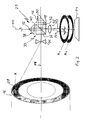
- the lighting device 10 shown in FIG. 1 has one single-mode laser diode 12 with a wave range of approx. 800 nm and a power of approx. 100 mW based on the Center axis 14 of a pneumatic tire 16 at a distance from the pneumatic tire 16 is arranged.
- the central axis 14 usually a cylindrical lens 18 or similar working lens arranged.
- the one from a laser diode 12 emerging light beam typically has an elliptical one Cross-section.
- the opening angle is typically on the small ellipse axis 7 ° to 12 °, on the large ellipse axis 12 ° to 35 °.
- the cylindrical lens 18 With the cylindrical lens 18, the elliptical Beam cross section 20 approximately in a concentric Beam cross section 22 are converted.
- the one from the laser diode 12 has emerging beam 20, of the type of laser diode dependent, very different forms. Therefore, too other lenses or combinations of lenses to create the necessary concentric beam cross section to be advantageous.
- the Axikon 24 converts the beam cone 22 emerging from the cylindrical lens 18 into a Beam 26 with an annular cross section.
- the arrangement of the individual components is chosen so that the pneumatic tire 16th coaxial ring in the transition area between the belt package and carcass is illuminated, with the ring 28 preferably has a width on the order of 10 to 20 mm.
- the Laser diode 12, the cylindrical lens 18 and the axicon 24 the central axis of the pneumatic tire 16. If one such an arrangement is not for design reasons is possible, it is also possible to have these components on one to arrange at right angles to the central axis 14 straight lines.
- An adjustment device can also be used to adjust the ring width (not shown) may be provided.
- the test head 29 shown in FIG. 2 has an interferometer 30 on that arranged behind an optics 34 beam splitter 32 includes.
- the beam splitting surface 36 of the beam splitter 32 is arranged at an angle of 45 ° to the central axis 14, the Center axis 14 through the center of the beam splitting Surface 36 passes through. 2 is above the beam splitter 32 a first roof prism 38 is arranged.
- the base 40 of the first roof prism 38 runs parallel to the central axis 14.
- the center of the ridge edge 42 lies on one Straight line 44 perpendicular to the central axis 14 through the center the beam splitting surface 36.
- the roof prism 38 is arranged pivotably about the straight line 44.
- roof prism 46 is on the optics 34 facing away Side of the beam splitter 32 arranged so that its base 48th runs perpendicular to the central axis 14 and the center of the Ridge edge 50 is arranged on the central axis 14.
- the Levels of bases 40 and 48 are perpendicular to each other and intersect the plane of the beam splitting surface 36 in one 45 ° angle.
- the second roof prism 46 has a piezo translator connected, through which the second roof prism 46 very precisely can be moved along the central axis 14.
- the interferometer 30 On the lower exit side of the interferometer 30 is a Objective 52 of a CCD camera arranged. Below the lens 52, the CCD camera has a CCD chip as an image sensor system 54 on.
- the first roof prism 38 is slightly twisted about the straight line 44.
- a beam of a point A is illuminated Ring 28 of the test area of the pneumatic tire 16 through the lens 34 onto the beam splitting surface 36 of the beam splitter 32 redirected.
- a partial beam TS1 passes through the beam-splitting surface 36 through, is from the second roof prism 46 on the back of the beam splitting surface 36 reflected and reflected from there towards the lens 52.
- a second partial radiation TS2 is emitted by the beam splitter Surface 36 in the direction of the twisted first roof prism 38 reflected.
- the partial radiation reflected by the roof prism 38 TS2 passes through the beam splitting surface 36 and also hits the lens 52 of the CCD camera.
- test area 28 of the Test object typically mapped on a CCD chip 54.
- CCD chip 54 For better understanding of circumferential shearing the partial images A1 and A2 generated in the interferometer face up shown offset.
- the partial radiation TS1 of point A strikes the CCD chip a point A1, while the partial radiation TS2 in one Point A2 hits.
- the point A2 is with respect to the point A1 offset on a circular path at an angular distance ⁇ Center axis is formed by the straight line 44.
- ⁇ Center axis is formed by the straight line 44.
- a rotation shearing image is on the CCD chip 54 generated.
- the rotation of the roof prism 38 is selected so that two points in the illuminated ring 28, which is at a distance of about 7 mm on a coaxial to the central axis 14 arranged circular path, one above the other are imaged on the CCD chip 54.
- the one on the CCD chip during the two deformation states Images shown are each via an A / D converter fed to an image processing unit and known Processed further to a modulo 2Pi image (compare Osten W. "Digital processing and evaluation of interference images", Akademie Verlag, Berlin, 1991).
- the lowering the pressure in the pneumatic tire 16 is chosen so low that the test surface of the pneumatic tire 16 stands up during the deformation less than a wavelength of coherent light move, so the phase difference is less than 2II. In in this case there is no demodulation of the modulo 2Pi picture required. It is sufficient to adapt the modulo 2Pi image to suitable ones Way to filter.
- FIG. 3 shows the typical course of a deformation in the region of a bulge, the angle Winkel of the illuminated ring 28 of the test area of the pneumatic tire 16 being indicated as the abscissa and the deformation in ⁇ m being indicated as the ordinate.
- the second right curve also shows the course of the deformation, but is offset by the shearing amount ⁇ from the original deformation curve.
- Fig. 4 shows the intensity curve of a directly filtered Modulo-2Pi image in the area of the bulge, the ordinate being the Gray value is specified.
- the filtered Modulo-2Pi image in the area of the bump an approximately sinusoidal Course, the gray values initially to a maximum rise and then fall to a minimum.
- FIG. 5 shows the typical course of a deformation in the area of a dent, the angle ⁇ of the illuminated ring 28 of the test area of the pneumatic tire 16 being indicated as the abscissa and the deformation in ⁇ m being indicated as the ordinate.
- 6 shows the intensity profile of a directly filtered modulo 2Pi image in the area of the dent, the gray value being indicated as the ordinate. It can be seen that the filtered modulo-2Pi image also has an approximately sinusoidal profile, the curve initially falling to a minimum and then increasing to a maximum.
- the difference ⁇ S between maximum and minimum within this small one Calculation segment is defined as a threshold and sets Criterion for a tire defect.
- a predetermined one Threshold e.g. 50 gray values
- the defect can be indicated by a False color representation or another conspicuous signal, such as a warning tone or warning light.
Landscapes
- Physics & Mathematics (AREA)
- General Physics & Mathematics (AREA)
- Length Measuring Devices By Optical Means (AREA)
Priority Applications (2)
| Application Number | Priority Date | Filing Date | Title |
|---|---|---|---|
| EP99123608A EP1103785A1 (fr) | 1999-11-26 | 1999-11-26 | Procédé et dispositif pour la détection des changements de forme des objets toroidaux à examiner |
| CA002326286A CA2326286A1 (fr) | 1999-11-26 | 2000-11-20 | Procede et dispositif pour determiner tout changement de forme dans des objets de test toroidal |
Applications Claiming Priority (1)
| Application Number | Priority Date | Filing Date | Title |
|---|---|---|---|
| EP99123608A EP1103785A1 (fr) | 1999-11-26 | 1999-11-26 | Procédé et dispositif pour la détection des changements de forme des objets toroidaux à examiner |
Publications (1)
| Publication Number | Publication Date |
|---|---|
| EP1103785A1 true EP1103785A1 (fr) | 2001-05-30 |
Family
ID=8239467
Family Applications (1)
| Application Number | Title | Priority Date | Filing Date |
|---|---|---|---|
| EP99123608A Withdrawn EP1103785A1 (fr) | 1999-11-26 | 1999-11-26 | Procédé et dispositif pour la détection des changements de forme des objets toroidaux à examiner |
Country Status (2)
| Country | Link |
|---|---|
| EP (1) | EP1103785A1 (fr) |
| CA (1) | CA2326286A1 (fr) |
Cited By (2)
| Publication number | Priority date | Publication date | Assignee | Title |
|---|---|---|---|---|
| DE102014011873A1 (de) | 2014-08-11 | 2016-02-11 | Steinbichler Optotechnik Gmbh | Prüfgerät zum Prüfen eines Reifens |
| CN114910485A (zh) * | 2022-06-06 | 2022-08-16 | 绍兴织蛛物联科技有限公司 | 一种纺织品面料检测装置 |
Citations (5)
| Publication number | Priority date | Publication date | Assignee | Title |
|---|---|---|---|---|
| EP0352535A1 (fr) * | 1988-07-12 | 1990-01-31 | Eastman Kodak Company | Dispositif et méthode pour tester des surfaces circulaires cylindriques ou coniques |
| EP0480028A1 (fr) * | 1989-06-30 | 1992-04-15 | RENISHAW plc | Procede et dispositif de determination du profil de surface d'objets de diffusion-reflection |
| EP0641992A2 (fr) * | 1993-09-08 | 1995-03-08 | Texas Instruments Incorporated | Systèmes d'appareils et de méthodes pour mesurer des défauts de fabricage de semi-conducteurs |
| EP0893670A2 (fr) * | 1997-07-22 | 1999-01-27 | Beissbarth GmbH | Dispositif de contrÔle des pneus |
| GB2334345A (en) * | 1995-07-31 | 1999-08-18 | Tropel Corp | Interferometer with compound diffractive optics |
-
1999
- 1999-11-26 EP EP99123608A patent/EP1103785A1/fr not_active Withdrawn
-
2000
- 2000-11-20 CA CA002326286A patent/CA2326286A1/fr not_active Abandoned
Patent Citations (5)
| Publication number | Priority date | Publication date | Assignee | Title |
|---|---|---|---|---|
| EP0352535A1 (fr) * | 1988-07-12 | 1990-01-31 | Eastman Kodak Company | Dispositif et méthode pour tester des surfaces circulaires cylindriques ou coniques |
| EP0480028A1 (fr) * | 1989-06-30 | 1992-04-15 | RENISHAW plc | Procede et dispositif de determination du profil de surface d'objets de diffusion-reflection |
| EP0641992A2 (fr) * | 1993-09-08 | 1995-03-08 | Texas Instruments Incorporated | Systèmes d'appareils et de méthodes pour mesurer des défauts de fabricage de semi-conducteurs |
| GB2334345A (en) * | 1995-07-31 | 1999-08-18 | Tropel Corp | Interferometer with compound diffractive optics |
| EP0893670A2 (fr) * | 1997-07-22 | 1999-01-27 | Beissbarth GmbH | Dispositif de contrÔle des pneus |
Cited By (2)
| Publication number | Priority date | Publication date | Assignee | Title |
|---|---|---|---|---|
| DE102014011873A1 (de) | 2014-08-11 | 2016-02-11 | Steinbichler Optotechnik Gmbh | Prüfgerät zum Prüfen eines Reifens |
| CN114910485A (zh) * | 2022-06-06 | 2022-08-16 | 绍兴织蛛物联科技有限公司 | 一种纺织品面料检测装置 |
Also Published As
| Publication number | Publication date |
|---|---|
| CA2326286A1 (fr) | 2001-05-26 |
Similar Documents
| Publication | Publication Date | Title |
|---|---|---|
| EP0615607B1 (fr) | Appareil optique pour la mesure des distances | |
| EP3164695B1 (fr) | Procédé et dispositif de détermination d'un type de matériau et/ou d'une propriété de surface d'une pièce | |
| EP1904260B1 (fr) | Procede et dispositif pour determiner un mouvement relatif lateral entre une tete d'usinage et une piece | |
| EP0367924B1 (fr) | Procédé et dispositif pour déterminer la position d'un joint d'une soudure pour le soudage à laser | |
| DE4231578C2 (de) | Verfahren zur Ermittlung von Verformungen an einem Prüfobjekt mit diffus streuender Oberfläche, insbesondere an Reifen, sowie Vorrichtung zur Durchführung des Verfahrens | |
| DE2602001C3 (de) | Vorrichtung zur Überprüfung einer bearbeiteten Oberfläche eines Werkstucks | |
| DE2802416A1 (de) | Optische vorrichtung | |
| WO2005108919A1 (fr) | Dispositif de mesure comportant une pointe de contact optique | |
| EP2131145B1 (fr) | Dispositif de surveillance optique | |
| DE2235059A1 (de) | Verfahren und system zum untersuchen der oberflaechenqualitaet eines werkstuecks | |
| EP0152894B1 (fr) | Dispositif pour la détection optique d'inégalités locales dans la structure d'un objet examiné | |
| EP4325208A2 (fr) | Procédé et dispositif de détection de déplacements d'un échantillon par rapport à un objectif | |
| EP0329986A1 (fr) | Procédé et appareil pour l'acquisition optique du profil de la rugosité d'une surface de matière | |
| EP0704693A1 (fr) | Procédé et dispositif optique de contrÔle exhaustif de la qualité d'objets | |
| EP0704694A1 (fr) | Dispositif et méthode pour le contrÔle de la qualité d'objets par de la lumière polarisée | |
| EP0750735A1 (fr) | Procede de traitement d'image permettant de determiner la resistance structurale d'un objet a tester presentant une surface a dispersion diffuse | |
| DE3312203C2 (fr) | ||
| DE3020044C2 (fr) | ||
| EP1103785A1 (fr) | Procédé et dispositif pour la détection des changements de forme des objets toroidaux à examiner | |
| DE4434475A1 (de) | Verfahren und Vorrichtung zur Qualitätskontrolle eines Gegenstandes | |
| EP4010145B1 (fr) | Procédé d'analyse de la surface d'une pièce dans le cadre d'un processus d'usinage laser et dispositif d'analyse destiné à analyser la surface d'une pièce | |
| EP3751256B1 (fr) | Système de capteur optoélectronique permettant de détecter des objets dans une zone de surveillance | |
| DE3208042C1 (de) | Verfahren zum Pruefen von sich in einer Richtung bewegten Gegenstaenden | |
| EP1054361B1 (fr) | Procédé et dispositif pour reconnaítre la configuration spatiale des pièces de monnaie | |
| EP0567981B1 (fr) | Procédé pour la mensuration des profils courbés d'arêtes |
Legal Events
| Date | Code | Title | Description |
|---|---|---|---|
| PUAI | Public reference made under article 153(3) epc to a published international application that has entered the european phase |
Free format text: ORIGINAL CODE: 0009012 |
|
| AK | Designated contracting states |
Kind code of ref document: A1 Designated state(s): DE ES FR GB IT |
|
| AX | Request for extension of the european patent |
Free format text: AL;LT;LV;MK;RO;SI |
|
| 17P | Request for examination filed |
Effective date: 20011107 |
|
| AKX | Designation fees paid |
Free format text: DE ES FR GB IT |
|
| STAA | Information on the status of an ep patent application or granted ep patent |
Free format text: STATUS: THE APPLICATION IS DEEMED TO BE WITHDRAWN |
|
| 18D | Application deemed to be withdrawn |
Effective date: 20060601 |