EP1103734A1 - Simplified tightening device - Google Patents
Simplified tightening device Download PDFInfo
- Publication number
- EP1103734A1 EP1103734A1 EP00931682A EP00931682A EP1103734A1 EP 1103734 A1 EP1103734 A1 EP 1103734A1 EP 00931682 A EP00931682 A EP 00931682A EP 00931682 A EP00931682 A EP 00931682A EP 1103734 A1 EP1103734 A1 EP 1103734A1
- Authority
- EP
- European Patent Office
- Prior art keywords
- bolt
- base
- inclination angle
- screw
- running
- Prior art date
- Legal status (The legal status is an assumption and is not a legal conclusion. Google has not performed a legal analysis and makes no representation as to the accuracy of the status listed.)
- Withdrawn
Links
Images





Classifications
-
- F—MECHANICAL ENGINEERING; LIGHTING; HEATING; WEAPONS; BLASTING
- F16—ENGINEERING ELEMENTS AND UNITS; GENERAL MEASURES FOR PRODUCING AND MAINTAINING EFFECTIVE FUNCTIONING OF MACHINES OR INSTALLATIONS; THERMAL INSULATION IN GENERAL
- F16B—DEVICES FOR FASTENING OR SECURING CONSTRUCTIONAL ELEMENTS OR MACHINE PARTS TOGETHER, e.g. NAILS, BOLTS, CIRCLIPS, CLAMPS, CLIPS OR WEDGES; JOINTS OR JOINTING
- F16B39/00—Locking of screws, bolts or nuts
- F16B39/22—Locking of screws, bolts or nuts in which the locking takes place during screwing down or tightening
- F16B39/28—Locking of screws, bolts or nuts in which the locking takes place during screwing down or tightening by special members on, or shape of, the nut or bolt
- F16B39/30—Locking exclusively by special shape of the screw-thread
-
- F—MECHANICAL ENGINEERING; LIGHTING; HEATING; WEAPONS; BLASTING
- F16—ENGINEERING ELEMENTS AND UNITS; GENERAL MEASURES FOR PRODUCING AND MAINTAINING EFFECTIVE FUNCTIONING OF MACHINES OR INSTALLATIONS; THERMAL INSULATION IN GENERAL
- F16B—DEVICES FOR FASTENING OR SECURING CONSTRUCTIONAL ELEMENTS OR MACHINE PARTS TOGETHER, e.g. NAILS, BOLTS, CIRCLIPS, CLAMPS, CLIPS OR WEDGES; JOINTS OR JOINTING
- F16B37/00—Nuts or like thread-engaging members
- F16B37/08—Quickly-detachable or mountable nuts, e.g. consisting of two or more parts; Nuts movable along the bolt after tilting the nut
- F16B37/0807—Nuts engaged from the end of the bolt, e.g. axially slidable nuts
- F16B37/0857—Nuts engaged from the end of the bolt, e.g. axially slidable nuts with the threaded portions of the nut engaging the thread of the bolt by the action of one or more springs or resilient retaining members
Definitions
- the present invention relates to a simple fastening device that can be used in various machines, such as construction, electrical, or mechanical equipment, and that is capable of clamping by one-touch handling.
- a simple fastening device has (1) a base, inside of which is a conical hole that has a slope portion, (2) a plurality of running screws that are led by the conic hole and that expand or contract in the diametrical direction, while moving up and down according to the axial movement of an inserted bolt, (3) a spring that compresses a plurality of the aforementioned running screws in the contracting direction, and (4) a cap that is a crown on the upper region of the base and that pushes down the running screws through the spring so as to make contact with the base.
- the running screws have a slope portion that corresponds to the slope portion of the base. Furthermore, a female screw penetrates through the running screws in a vertical direction so as to be capable of being engaged with a male screw of the aforementioned bolt.
- This simple fastening device is to be fastened by using a bolt that is fixed to an object.
- a bolt that is fixed to an object.
- the edge of the female screw that is located on the bolt side of the running screws is brought into contact with the tip end of the bolt, thereby controlling the movement of the running screws in the direction indicated by the Arrow Y.
- the inserting force Fin is applied, the base moves in the direction indicated by the Arrow Y, and at the same time it compresses the spring.
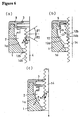
- the load FL produces the load W, which is applied to the slope portion of the base by the running screws.
- the slope angle ⁇ 3 of the slope portion of the base is necessarily made larger than both the inclination angle ⁇ 2 of the upper-side slope of the screw thread of the running screws and the corresponding inclination angle ⁇ 2, which is equal to the former, of the lower-side slope of the screw thread of the bolt.
- the inclination angle ⁇ 3 of the slope portion is increased, the upward movement of each running screw becomes larger so as to disengage the screw portion when a nut is fitted to the bolt.
- the spring accordingly needs to be longer in order to secure such a stroke.
- the simple fastening device must be large in size and tall in height.
- the present invention is made in consideration of the above-mentioned problems. Its purpose is to provide simple fastening devices that are capable of functioning well although using a reduced level of bolt-inserting force, while make the inserting work easier to perform, and that can be small in size though nonetheless of sufficient strength to perform the fastening work.
- the invention set forth in Claim 1 has (1) a base inside of which a conical hole with a slope is formed, (2) running screws that (a) are completely penetrated by a female screw to be engaged with the bolt, (b) are guided into the aforementioned conical hole, and (c) expand and contract according to the axial movement of the bolt that is inserted into the aforementioned base, (3) a spring that pushes the running screws against the surface of the aforementioned conical hole, and (4) a cap that (a) has a bolt-insertion hole, (b) is attached to the aforementioned base so as to press the aforementioned spring, and (c) is characterized such that the inclination angle of the lower-side slope is larger than the inclination angle of the upper-side slope of the screw thread on the female screw of the aforementioned running screws.
- the diameter-expanding force of the running screws which is produced by the inserting force of the bolt, is increased because the inclination angle of the lower-side slope is larger than the inclination angle of the upper-side slope of the screw thread of the female screw of the running screws. Consequently, the bolt is more easily inserted with less force.
- the diameter-expanding force, working on the slope portion of the base is reduced, because the inclination angle of the upper-side slope is smaller than the inclination angle of the lower-side slope of the screw thread of the female screw of the aforementioned running screws.
- the base is not damaged, and it is not necessary to increase the thickness of the base.
- the running screw can move along the slope portion, even if the inclination angle of the slope portion of the base is small the spring force can be small and a short spring can be used, which makes it possible to miniaturize the device.
- the invention set forth in Claim 2 is the invention as set forth in Claim 1, but is characterized such that the inclination angle of the upper-side slope is larger than the inclination angle of the lower-side slope of the screw thread of the male screw of the aforementioned bolt.
- the workings of the Claim 1 invention can be more easily and steadily done because the screw thread of the bolt corresponds to the screw thread of the running screws in Claim 1.
- Figures 1 through 4 represent a simple fastening device 10 as one embodiment of the present invention.
- Figure 1 illustrates the state of the device before fastening work
- Figure 2 illustrates the base
- Figures 3 and 4 illustrate the state of fastening work.
- the same numbers and symbols are used for the elements that are the same in the figures showing the prior art.
- the simple fastening device 10 in this embodiment is equipped with a base 1, running screws 2, a spring 3, and a cap 9. This device is used for fastening the base to the bolt 4, which is fixed to an object 5.
- half-doughnut-like holes 1e are formed opposite to each other in the base 1.
- Each of the half-doughnut-like holes 1e adjoins a conical hole 1b, which has a slope portion 1a.
- These half-doughnut-like holes and conical holes, which taken together form a single hole, have an upper-end hole-portion 1c and a lower-end hole-portion 1d, are formed in the base 1 along its axial line.
- a bolt 4 is inserted from the lower-end hole-portion 1d.
- 2 running screws 2 are inserted into the base 1, and the lower-end region of one of the 2 opposite slope portions 1a of the conical holes 1b is displaced toward the axial line by 1/2 P, which is one-half of the screw pitch of the female screw 2b of the running screws 2. If more than 2 running screws are set, the lower-end of the slope portion 1a of the conical hole 1b can be displaced toward the axial line by the distance of one screw pitch divided by the number of the running screws.
- Each of the running screws 2 is shaped like a half-doughnut, inside of which a female screw 2b is formed, as shown in Figure 1 (b).
- a half-conical slope portion 2a which corresponds to the slope portion 1a of the conical hole 1b of the base 1 is formed. This slope portion 2a contacts with the slope portion 1a of the conical hole 1b.
- a stepped spring-receptor portion 2c for receiving the spring 3.
- Each running screw 2 is inserted into the base 1 from the upper end hole-portion 1c and is set into the base 1 such that the screw's slope portion 2a contacts the slope portion 1a of the base 1.
- the 2 running screws 2 in a pair can slide up and down along the slope portion 1a of the base 1.
- the 2 running screws 2 also have corresponding female screws 2b, which are opposite to each other.
- Each female screw 2b thus penetrates through its respective running screw 2.
- the female screw 2b is to be engaged with the male screw 4b of the bolt 4.
- the spring 3 is set on the spring-receptor portion 2c of the running screw 2.
- the cap 9 covers the base 1 and is hooked and fixed into the base 1, whereby the spring 3 pushes the running screw 2.
- the running screw 2 is thus pushed against and kept in contact with the slope portion 1a of the base 1.
- threads 4b like those on a male screw are formed.
- the device of such a structure can be moved along the Arrow Y, and when the bolt 4 on the object 5 is inserted into the base 1, the device is brought into contact with the object 5.
- the female screw 2b of the running screws 2 and the male screw of the bolt 4 are engaged. The fastening work is done by this engagement.
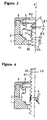
- Figures 3 and 4 illustrate the relationship between the female screw 2b of the running screw 2 and the male screw 4b of the bolt 4 in the above-mentioned embodiment.
- the inclination angle ⁇ 1 of the lower-side slope 21 is designed to be larger than the inclination angle ⁇ 2 of the upper-side slope 22 on each screw thread 20 ( ⁇ 1 > ⁇ 2).
- the tooth profile of the female screw 2b is saw-edged.
- the inclination angle of the lower-side slope 41 of each screw thread 40 is ⁇ 2
- the inclination angle of the upper-side slope 42 is ⁇ 1. Consequently, the inclination angle of the upper-side slope 42 is designed to be larger than the inclination angle of the lower-side slope 41. Accordingly, the male screw of the bolt 4 is also formed to be saw-edged.
- the inserting force Fin produces the force F1 on the surface of the upper-side slope 42 of the screw thread 40 on the bolt 4, and that force is exerted against the running screw 2 so as to expand the diameter of the running screw.
- the inclination angle on the lower-side slope 21 is designed to be larger than the inclination angle on the upper-side slope 22 of each screw thread 20 of the female screw 2b of the running screws 2, and also the inclination angle of the upper-side slope 42 is designed to be larger than the inclination angle of the lower-side slope 41 of each screw thread 40 of the bolt 4.
- the inclination angles of the lower-side slope 21 of the female screw 2b and of the upper-side slope 42 of the bolt 4 are larger than the inclination angle of the screw thread in the prior art.
- the inclination angle ⁇ 2 of the upper-side slope 22 is designed to be smaller than the inclination angle ⁇ 1 of the lower-side slope 21 of each screw thread 20 of the running screws 2, while the inclination angle of the lower-side slope 41 is designed to be smaller than the inclination angle of the upper-side slope 42 of each screw thread 40 of the bolt 4, so as to make these angles smaller than the inclination angle of the screw thread of the prior art.
- This makes the diameter-expanding-direction force W smaller, preventing the force W from damaging the base 1. Because the base is not damaged, greater fastening force can be applied if the thickness of the base 1 is the same as that in the prior art, and thereby the fastening strength can be improved.
- the device can be used in less-spacious places because it does not require that the base 1 be of large thickness.
- the downward load becomes large, but damage of the lower parts is prevented because of the reinforcement by the object 5 on which the bolt 4 is fixed.
- the running screws 2 can move along the slope portion 1a of the base 1 in the direction indicated by Arrow b, as shown in Figure 6 (c), even when the slope portion 1a of the base 1 has a smaller inclination angle of ⁇ 3.
- the movement of the running screws 2 that is required to disengage the screws is reduced.
- the simple fastening device of the present invention has the following effects:
Landscapes
- Engineering & Computer Science (AREA)
- General Engineering & Computer Science (AREA)
- Mechanical Engineering (AREA)
- Details Of Spanners, Wrenches, And Screw Drivers And Accessories (AREA)
- Bolts, Nuts, And Washers (AREA)
- Joining Of Building Structures In Genera (AREA)
Abstract
A simplified tightening device capable of reducing a bolt inserting force and
also providing a high tightening force, comprising a base (1) in which a conical hole with
slanted surface is formed, a thread block (2) through which a female screw (2b) to be threaded
with a bolt (4) is passed and which is guided by the conical hole and expanded or contracted
according to the axial movement of the bolt (4) inserted into the base (1), a spring (3) pressing
the thread block (2) against the conical hole, and a cap (9) which is provided with a bolt inserting
hole (9a), installed on the base (1), and presses the spring (3), wherein the inclination
angle of the lower side slanted surfaces (21) of the threads (20) of the female thread (2b) on
the thread block (2) is made larger than the inclination angle of the upper side slanted surface
(22).
Description
The present invention relates to a simple fastening
device that can be used in various machines, such as
construction, electrical, or mechanical equipment, and that
is capable of clamping by one-touch handling.
Both examined Japanese Patent Publication No. S55-48171
and unexamined Japanese Patent Publication No. H7-197922
each disclose one example of prior art of a simple fastening
device that is capable of clamping by one-touch handling.
Figures 5 (a) and 5 (b) illustrate the working of a simple
fastening device of such prior art.
A simple fastening device has (1) a base, inside of which
is a conical hole that has a slope portion, (2) a plurality
of running screws that are led by the conic hole and that
expand or contract in the diametrical direction, while moving
up and down according to the axial movement of an inserted
bolt, (3) a spring that compresses a plurality of the
aforementioned running screws in the contracting direction,
and (4) a cap that is a crown on the upper region of the base
and that pushes down the running screws through the spring
so as to make contact with the base.
The running screws have a slope portion that corresponds
to the slope portion of the base. Furthermore, a female screw
penetrates through the running screws in a vertical direction
so as to be capable of being engaged with a male screw of
the aforementioned bolt.
This simple fastening device is to be fastened by using
a bolt that is fixed to an object. As shown in Figure 5 (a),
pushing the bolt down in the direction indicated by the Arrow
Y, the edge of the female screw that is located on the bolt
side of the running screws is brought into contact with the
tip end of the bolt, thereby controlling the movement of the
running screws in the direction indicated by the Arrow Y.
In this state, if the inserting force Fin is applied, the
base moves in the direction indicated by the Arrow Y, and
at the same time it compresses the spring.
This produces a clearance between the slope portion of
the running screws and the slope portion of the base, and
the running screws accordingly move in the direction of the
inserting force Fin with a reaction force F1 (see Figure 6
(a)) that is produced by the inserting force Fin. That is,
when the running screws expand along the diametrical line
and move in a diametrical direction by the height of the screw
thread of the running screws, the bolt and the running screws
are disengaged. This enables the insertion of one pitch of
the screw. Therefore, continual application of the inserting
force Fin, when combined with repetition of the
above-mentioned action, enables the bolt to be inserted as
far as the object without rotating the whole device.
After the insertion of the bolt until it contacts the
object, if the bolt is a right-handed screw, the base is rotated
in a clockwise direction, as shown by the arrow in Figure
5 (b). With this rotation, a load FL is produced on the
lower-side slope of the screw thread that is on the male screw
of the bolt, as shown in Figure 6 (c). As a result, the running
screws are caused to move along the surface of the slope portion
of the base in the direction indicated by Arrow b so as to
be engaged with the bolt. The fastening work is thus completed.
However, conventional simple fastening devices have the
following problems:
As shown in Figure 6 (c), the load FL produces the load
W, which is applied to the slope portion of the base by the
running screws. In this case, the running screws are capable
of moving in the direction indicated by Arrow B with the load
Δ W1 if the slope angle 3 of the slope portion of the base
is larger than the inclination angle 2 of the upper-side slope
of the screw thread furnished on the running screws (2 =
30 degrees, and 3 = 45 degrees, for example), as shown in
Figure 7 (c). If, however, 3 is smaller than 2, as shown
in Figure 7 (b), the load Δ W2 applies, which moves above
the slope portion 1a. Figure 7 (a) illustrates the case of
2 = 3, where ΔW1 and Δ W2 do not apply.
To move the running screws in the direction indicated
by Arrow B, therefore, the slope angle 3 of the slope portion
of the base is necessarily made larger than both the inclination
angle 2 of the upper-side slope of the screw thread of the
running screws and the corresponding inclination angle
2, which is equal to the former, of the lower-side slope of
the screw thread of the bolt. However, if the inclination
angle 3 of the slope portion is increased, the upward movement
of each running screw becomes larger so as to disengage the
screw portion when a nut is fitted to the bolt. The spring
accordingly needs to be longer in order to secure such a stroke.
As a result, the simple fastening device must be large in
size and tall in height.
The present invention is made in consideration of the
above-mentioned problems. Its purpose is to provide simple
fastening devices that are capable of functioning well
although using a reduced level of bolt-inserting force, while
make the inserting work easier to perform, and that can be
small in size though nonetheless of sufficient strength to
perform the fastening work.
For the aforementioned purpose, the invention set forth
in Claim 1 has (1) a base inside of which a conical hole with
a slope is formed, (2) running screws that (a) are completely
penetrated by a female screw to be engaged with the bolt,
(b) are guided into the aforementioned conical hole, and (c)
expand and contract according to the axial movement of the
bolt that is inserted into the aforementioned base, (3) a
spring that pushes the running screws against the surface
of the aforementioned conical hole, and (4) a cap that (a)
has a bolt-insertion hole, (b) is attached to the
aforementioned base so as to press the aforementioned spring,
and (c) is characterized such that the inclination angle of
the lower-side slope is larger than the inclination angle
of the upper-side slope of the screw thread on the female
screw of the aforementioned running screws.
In the case of this invention, the diameter-expanding
force of the running screws, which is produced by the inserting
force of the bolt, is increased because the inclination angle
of the lower-side slope is larger than the inclination angle
of the upper-side slope of the screw thread of the female
screw of the running screws. Consequently, the bolt is more
easily inserted with less force.
Furthermore, the diameter-expanding force, working on
the slope portion of the base, is reduced, because the
inclination angle of the upper-side slope is smaller than
the inclination angle of the lower-side slope of the screw
thread of the female screw of the aforementioned running screws.
As a result, the base is not damaged, and it is not necessary
to increase the thickness of the base. Also, because the
running screw can move along the slope portion, even if the
inclination angle of the slope portion of the base is small
the spring force can be small and a short spring can be used,
which makes it possible to miniaturize the device.
The invention set forth in Claim 2 is the invention as
set forth in Claim 1, but is characterized such that the
inclination angle of the upper-side slope is larger than the
inclination angle of the lower-side slope of the screw thread
of the male screw of the aforementioned bolt.
In the case of this invention, the workings of the Claim
1 invention can be more easily and steadily done because the
screw thread of the bolt corresponds to the screw thread of
the running screws in Claim 1.
Figures 1 through 4 represent a simple fastening device
10 as one embodiment of the present invention. Figure 1
illustrates the state of the device before fastening work,
Figure 2 illustrates the base, and Figures 3 and 4 illustrate
the state of fastening work. The same numbers and symbols
are used for the elements that are the same in the figures
showing the prior art. The simple fastening device 10 in this
embodiment is equipped with a base 1, running screws 2, a
spring 3, and a cap 9. This device is used for fastening the
base to the bolt 4, which is fixed to an object 5.
As shown in Figure 2, half-doughnut-like holes 1e are
formed opposite to each other in the base 1. Each of the
half-doughnut-like holes 1e adjoins a conical hole 1b, which
has a slope portion 1a. These half-doughnut-like holes and
conical holes, which taken together form a single hole, have
an upper-end hole-portion 1c and a lower-end hole-portion
1d, are formed in the base 1 along its axial line. A bolt
4 is inserted from the lower-end hole-portion 1d. In this
embodiment, 2 running screws 2 are inserted into the base
1, and the lower-end region of one of the 2 opposite slope
portions 1a of the conical holes 1b is displaced toward the
axial line by 1/2 P, which is one-half of the screw pitch
of the female screw 2b of the running screws 2. If more than
2 running screws are set, the lower-end of the slope portion
1a of the conical hole 1b can be displaced toward the axial
line by the distance of one screw pitch divided by the number
of the running screws.
Each of the running screws 2 is shaped like a half-doughnut,
inside of which a female screw 2b is formed, as shown in Figure
1 (b). On the outside surface of the running screw 2, a
half-conical slope portion 2a, which corresponds to the slope
portion 1a of the conical hole 1b of the base 1 is formed.
This slope portion 2a contacts with the slope portion 1a of
the conical hole 1b. On the top portion of the running screw
2, there is formed a stepped spring-receptor portion 2c for
receiving the spring 3.
Each running screw 2 is inserted into the base 1 from
the upper end hole-portion 1c and is set into the base 1 such
that the screw's slope portion 2a contacts the slope portion
1a of the base 1. In this state, the 2 running screws 2 in
a pair can slide up and down along the slope portion 1a of
the base 1. As the running screws 2 slides, they expand or
contract. In the set-circumstances, the 2 running screws 2
also have corresponding female screws 2b, which are opposite
to each other. Each female screw 2b thus penetrates through
its respective running screw 2. The female screw 2b is to
be engaged with the male screw 4b of the bolt 4.
The spring 3 is set on the spring-receptor portion 2c
of the running screw 2. In this state, the cap 9 covers the
base 1 and is hooked and fixed into the base 1, whereby the
spring 3 pushes the running screw 2. The running screw 2 is
thus pushed against and kept in contact with the slope portion
1a of the base 1. Furthermore, there is formed in the cap
9 a bolt-inserting hole 9a, into which the bolt 4 is inserted.
On the outside surface of the bolt 4 on the object 5, threads
4b like those on a male screw are formed.
As shown in Figure 1, the device of such a structure
can be moved along the Arrow Y, and when the bolt 4 on the
object 5 is inserted into the base 1, the device is brought
into contact with the object 5. By rotating the base 1 in
this contact state, the female screw 2b of the running screws
2 and the male screw of the bolt 4 are engaged. The fastening
work is done by this engagement.
Figures 3 and 4 illustrate the relationship between the
female screw 2b of the running screw 2 and the male screw
4b of the bolt 4 in the above-mentioned embodiment. In the
case of the female screw 2b of the running screw 2, as shown
in Figure 3, the inclination angle 1 of the lower-side slope
21 is designed to be larger than the inclination angle 2
of the upper-side slope 22 on each screw thread 20 (1 >
2). For this reason, the tooth profile of the female screw
2b is saw-edged. Furthermore, in the case of the male screw
4b of the bolt 4, the inclination angle of the lower-side
slope 41 of each screw thread 40, is 2, and the inclination
angle of the upper-side slope 42 is 1. Consequently, the
inclination angle of the upper-side slope 42 is designed to
be larger than the inclination angle of the lower-side slope
41. Accordingly, the male screw of the bolt 4 is also formed
to be saw-edged.
When such a simple fastening device overlaps a bolt 4
along the direction indicated by Arrow Y in Figure 1 so as
to receive the bolt 4, the inserting force Fin produces the
force F1 on the surface of the upper-side slope 42 of the
screw thread 40 on the bolt 4, and that force is exerted against
the running screw 2 so as to expand the diameter of the running
screw. In the case of this embodiment, the inclination angle
on the lower-side slope 21 is designed to be larger than the
inclination angle on the upper-side slope 22 of each screw
thread 20 of the female screw 2b of the running screws 2,
and also the inclination angle of the upper-side slope 42
is designed to be larger than the inclination angle of the
lower-side slope 41 of each screw thread 40 of the bolt 4.
Therefore, the inclination angles of the lower-side slope
21 of the female screw 2b and of the upper-side slope 42 of
the bolt 4 are larger than the inclination angle of the screw
thread in the prior art. This makes it possible to increase
the diameter-expanding force F1 that results from an increased
inserting force Fin, and to make the running screws 2 more
easily expand along the diameter, and as a result, to make
the running screws 2 more easily disengaged from the male
screw 4b of the bolt 4. For this reason, it is possible to
insert the bolt 4 with a smaller inserting force, as well
as to insert it smoothly, without occurring a galling
phenomenon.
After this simple fastening device 10 is inserted so
as to contact with the object 5, to which the bolt 4 is fixed,
if it is a right-handed screw a clockwise rotation causes,
with a force applied by the lower-side slope 41 of the screw
thread 40 on the bolt 4, the running screws 2 to move along
the slope portion 1a of the conical hole 1b in the direction
indicated by Arrow b, as shown by Figure 6 (c). Thus, the
running screw 2 is engaged and fastened to the bolt 4. In
this fastening work, a diameter-expanding direction force
W works on the slope portion 1a of the base 1. In this embodiment,
the inclination angle 2 of the upper-side slope 22 is designed
to be smaller than the inclination angle 1 of the lower-side
slope 21 of each screw thread 20 of the running screws 2,
while the inclination angle of the lower-side slope 41 is
designed to be smaller than the inclination angle of the
upper-side slope 42 of each screw thread 40 of the bolt 4,
so as to make these angles smaller than the inclination angle
of the screw thread of the prior art. This makes the
diameter-expanding-direction force W smaller, preventing the
force W from damaging the base 1. Because the base is not
damaged, greater fastening force can be applied if the
thickness of the base 1 is the same as that in the prior art,
and thereby the fastening strength can be improved.
Furthermore, the device can be used in less-spacious places
because it does not require that the base 1 be of large
thickness.
In this embodiment, the downward load becomes large,
but damage of the lower parts is prevented because of the
reinforcement by the object 5 on which the bolt 4 is fixed.
Furthermore, in this embodiment, because the inclination
angle 2 at the upper-side slope 22 of each screw thread 20
of the running screws 2 and the inclination angle of the
lower-side slope 41 of each screw thread 40 of the bolt 4
are designed to be smaller than the inclination angle of the
screw thread of the prior art, the running screws 2 can move
along the slope portion 1a of the base 1 in the direction
indicated by Arrow b, as shown in Figure 6 (c), even when
the slope portion 1a of the base 1 has a smaller inclination
angle of 3. As a result, the movement of the running screws
2 that is required to disengage the screws is reduced. This
makes the compression volume by the spring 3 accordingly
smaller, which enables the device to have a lower height and
to be smaller in size overall.
As explained above, the simple fastening device of the
present invention has the following effects:
Claims (2)
- A simple fastening device that has (1) a base, inside of which a conical hole having a slope is formed, (2) running screws that are penetrated by a female screw that is engaged with a bolt and that is led by the aforementioned conical hole and that expands and contracts according to the axial movement of the bolt inserted into the aforementioned base, (3) a spring that pushes the running screws against the aforementioned conical hole, and (4) a cap that is a crown on the upper region of the base, that holds the aforementioned spring, and that is characterized such that the inclination angle of the lower-side slope of the screw thread is designed to be larger than the inclination angle of the upper-side slope in the female screw of the running screws.
- A simple fastening device as set forth in Claim 1, which is characterized such that the inclination angle of the upper-side slope of the screw thread is designed to be larger than the inclination angle of the lower-side slope in the aforementioned bolt.
Applications Claiming Priority (3)
| Application Number | Priority Date | Filing Date | Title |
|---|---|---|---|
| JP15761899 | 1999-06-04 | ||
| JP11157618A JP2000346034A (en) | 1999-06-04 | 1999-06-04 | Simple fastening device |
| PCT/JP2000/003615 WO2000075519A1 (en) | 1999-06-04 | 2000-06-02 | Simplified tightening device |
Publications (2)
| Publication Number | Publication Date |
|---|---|
| EP1103734A1 true EP1103734A1 (en) | 2001-05-30 |
| EP1103734A4 EP1103734A4 (en) | 2004-03-24 |
Family
ID=15653676
Family Applications (1)
| Application Number | Title | Priority Date | Filing Date |
|---|---|---|---|
| EP00931682A Withdrawn EP1103734A4 (en) | 1999-06-04 | 2000-06-02 | SIMPLIFIED TIGHTENING DEVICE |
Country Status (3)
| Country | Link |
|---|---|
| EP (1) | EP1103734A4 (en) |
| JP (1) | JP2000346034A (en) |
| WO (1) | WO2000075519A1 (en) |
Cited By (6)
| Publication number | Priority date | Publication date | Assignee | Title |
|---|---|---|---|---|
| GB2404708A (en) * | 2003-08-05 | 2005-02-09 | Paul Wilson | Push on nut |
| EP1793131A1 (en) * | 2005-11-30 | 2007-06-06 | Dietz-automotive GmbH & Co. KG | Device for fixing an object in position |
| EP2474749A1 (en) * | 2011-01-07 | 2012-07-11 | Haweka AG | Quick tensioning nut, in particular for fixing a vehicle tyre to the tension shaft of a balancing machine |
| US9945115B2 (en) | 2013-10-08 | 2018-04-17 | Simpson Strong-Tie Company, Inc. | Concrete anchor |
| USRE48981E1 (en) | 2014-01-14 | 2022-03-22 | Simpson Strong-Tie Company Inc. | Thrust nut |
| US11976461B2 (en) | 2020-12-03 | 2024-05-07 | UNIVERSITé LAVAL | Snap joint and method of use |
Families Citing this family (3)
| Publication number | Priority date | Publication date | Assignee | Title |
|---|---|---|---|---|
| JP4654009B2 (en) * | 2004-11-22 | 2011-03-16 | 株式会社三ツ知 | CONNECTING DEVICE AND CONCRETE MEMBER CONNECTING DEVICE USING THE SAME |
| SG185677A1 (en) * | 2010-05-26 | 2012-12-28 | Schwihag Ag | Plastic screw plug for attaching a rail to a sleeper |
| JP7742608B2 (en) * | 2022-01-28 | 2025-09-22 | 北海道瓦斯株式会社 | Threaded and squeeze-off devices |
Family Cites Families (7)
| Publication number | Priority date | Publication date | Assignee | Title |
|---|---|---|---|---|
| DE839292C (en) * | 1944-01-24 | 1952-05-19 | Wilhelm Abel | Screw connection with nut and screw |
| US3151652A (en) * | 1958-02-26 | 1964-10-06 | Victor F Zahodiakin | Fastening devices |
| US3151653A (en) * | 1959-06-17 | 1964-10-06 | Victor F Zahodfakin | Quick-locking fastening device |
| JPH0477017U (en) * | 1990-11-20 | 1992-07-06 | ||
| JP3177870B2 (en) * | 1993-12-28 | 2001-06-18 | 日本発条株式会社 | Simple fastening device |
| AT401189B (en) * | 1994-09-15 | 1996-07-25 | Bundes Fuer Industriepolitisch | DEVICE FOR FASTENING TWO COMPONENTS TOGETHER |
| JPH08177839A (en) * | 1994-12-22 | 1996-07-12 | Nitto Seiko Co Ltd | Loosening prevention screw |
-
1999
- 1999-06-04 JP JP11157618A patent/JP2000346034A/en active Pending
-
2000
- 2000-06-02 WO PCT/JP2000/003615 patent/WO2000075519A1/en not_active Ceased
- 2000-06-02 EP EP00931682A patent/EP1103734A4/en not_active Withdrawn
Cited By (9)
| Publication number | Priority date | Publication date | Assignee | Title |
|---|---|---|---|---|
| GB2404708A (en) * | 2003-08-05 | 2005-02-09 | Paul Wilson | Push on nut |
| EP1793131A1 (en) * | 2005-11-30 | 2007-06-06 | Dietz-automotive GmbH & Co. KG | Device for fixing an object in position |
| EP2474749A1 (en) * | 2011-01-07 | 2012-07-11 | Haweka AG | Quick tensioning nut, in particular for fixing a vehicle tyre to the tension shaft of a balancing machine |
| CN102734301A (en) * | 2011-01-07 | 2012-10-17 | 霍韦卡股份公司 | Quick adjusting nut, especially for attaching vehicle wheel to the mounting shaft of balancing machine |
| CN102734301B (en) * | 2011-01-07 | 2015-04-29 | 霍韦卡股份公司 | Quick adjusting nut, especially for attaching vehicle wheel to the mounting shaft of balancing machine |
| US9217457B2 (en) | 2011-01-07 | 2015-12-22 | Haweka Ag | Quick adjusting nut, especially for attaching a vehicle wheel to the mounting shaft of a balancing machine |
| US9945115B2 (en) | 2013-10-08 | 2018-04-17 | Simpson Strong-Tie Company, Inc. | Concrete anchor |
| USRE48981E1 (en) | 2014-01-14 | 2022-03-22 | Simpson Strong-Tie Company Inc. | Thrust nut |
| US11976461B2 (en) | 2020-12-03 | 2024-05-07 | UNIVERSITé LAVAL | Snap joint and method of use |
Also Published As
| Publication number | Publication date |
|---|---|
| WO2000075519A1 (en) | 2000-12-14 |
| JP2000346034A (en) | 2000-12-12 |
| EP1103734A4 (en) | 2004-03-24 |
Similar Documents
| Publication | Publication Date | Title |
|---|---|---|
| JP5643338B2 (en) | Nuts with lug flare | |
| US7445525B2 (en) | Battery terminal | |
| CN1457401B (en) | Anti-loosening fasteners | |
| EP1283373B1 (en) | Structure for preventing loosening of threaded fasteners | |
| US11242882B2 (en) | Staking bolt | |
| CA2782918C (en) | A functional element having features preventing rotation and associated sheet metal assembly | |
| US6109849A (en) | Tee nut | |
| US5256019A (en) | Washerless self-captivating screw | |
| CN102449853A (en) | Slip ring contact coaxial connector | |
| EP1676675A1 (en) | Tool for tightening security nut, tool for releasing security nut, tool for both tightening and releasing security nut, and security nut for exclusive use of these tools | |
| JPH0597056U (en) | Battery terminal | |
| CN109690873B (en) | copper busbar | |
| KR102304628B1 (en) | Attachment/detachment device for clamp arm of clamping device | |
| EP4530012B1 (en) | Mounting method for anti-off elastic retaining ring | |
| US6994486B1 (en) | Functional element and panel assembly | |
| US6155761A (en) | Short point anti-cross-threading design | |
| JP2003500214A (en) | Method and apparatus for securing an auxiliary connection element to a sheet-like workpiece and a work piece having an auxiliary connection element | |
| JP4609811B2 (en) | Punch assembly | |
| JP2000346034A (en) | Simple fastening device | |
| HK1038988A1 (en) | Terminal connector and method of manufacturing the terminal connector | |
| US5946786A (en) | Joining jig and joining member coupling method using the joining jig | |
| CN115298445B (en) | tightening nut | |
| US8016533B2 (en) | Lock nut with low on/high off torque control | |
| EP1584826B1 (en) | Threaded insert with knurl | |
| US5516247A (en) | Fastening device |
Legal Events
| Date | Code | Title | Description |
|---|---|---|---|
| PUAI | Public reference made under article 153(3) epc to a published international application that has entered the european phase |
Free format text: ORIGINAL CODE: 0009012 |
|
| AK | Designated contracting states |
Kind code of ref document: A1 Designated state(s): AT BE CH CY DE DK ES FI FR GB GR IE IT LI LU MC NL PT SE |
|
| 17P | Request for examination filed |
Effective date: 20010523 |
|
| A4 | Supplementary search report drawn up and despatched |
Effective date: 20040209 |
|
| RBV | Designated contracting states (corrected) |
Designated state(s): DE FR GB |
|
| STAA | Information on the status of an ep patent application or granted ep patent |
Free format text: STATUS: THE APPLICATION IS DEEMED TO BE WITHDRAWN |
|
| 18D | Application deemed to be withdrawn |
Effective date: 20040420 |