EP1103440A1 - Body of a carriage for railway passenger traffic - Google Patents
Body of a carriage for railway passenger traffic Download PDFInfo
- Publication number
- EP1103440A1 EP1103440A1 EP00124488A EP00124488A EP1103440A1 EP 1103440 A1 EP1103440 A1 EP 1103440A1 EP 00124488 A EP00124488 A EP 00124488A EP 00124488 A EP00124488 A EP 00124488A EP 1103440 A1 EP1103440 A1 EP 1103440A1
- Authority
- EP
- European Patent Office
- Prior art keywords
- car body
- body according
- wall
- roof
- long beam
- Prior art date
- Legal status (The legal status is an assumption and is not a legal conclusion. Google has not performed a legal analysis and makes no representation as to the accuracy of the status listed.)
- Withdrawn
Links
Images


Classifications
-
- B—PERFORMING OPERATIONS; TRANSPORTING
- B61—RAILWAYS
- B61D—BODY DETAILS OR KINDS OF RAILWAY VEHICLES
- B61D17/00—Construction details of vehicle bodies
- B61D17/04—Construction details of vehicle bodies with bodies of metal; with composite, e.g. metal and wood body structures
-
- Y—GENERAL TAGGING OF NEW TECHNOLOGICAL DEVELOPMENTS; GENERAL TAGGING OF CROSS-SECTIONAL TECHNOLOGIES SPANNING OVER SEVERAL SECTIONS OF THE IPC; TECHNICAL SUBJECTS COVERED BY FORMER USPC CROSS-REFERENCE ART COLLECTIONS [XRACs] AND DIGESTS
- Y02—TECHNOLOGIES OR APPLICATIONS FOR MITIGATION OR ADAPTATION AGAINST CLIMATE CHANGE
- Y02T—CLIMATE CHANGE MITIGATION TECHNOLOGIES RELATED TO TRANSPORTATION
- Y02T30/00—Transportation of goods or passengers via railways, e.g. energy recovery or reducing air resistance
Definitions
- the invention relates to a car body of a rail vehicle for the transportation of people with a base, side walls containing door openings, a roof and end walls.
- the invention has for its object a body of the generic type Kind so that the side walls with a view to flexible Design regarding the arrangement of door openings and possibly also Windows do not have a supporting function.
- This object is achieved in that between the Underframe and the roof one in the longitudinal center of the car body vertical middle wall is arranged as a supporting element.
- the vertical middle wall transfers all occurring loads between the base frame and roof.
- the side walls are not included in this power transmission, so that they - completely free of static constraints of known construction methods - ever depending on the area of application of the rail vehicle with different door arrangements and window dividers can be executed.
- Rail vehicle as mass transport (metro) can be the number of Door openings in the sense of a rapid change of passengers can be maximized.
- the underframe 1 of the car body has a central long beam 1a on, which can be designed as a box girder or as a double-T girder.
- This middle long beam 1a is connected to cross beams 1b, which is above here drives, not shown, are designed as main cross members.
- the roof has also preferably a box girder or double-T girder middle long beam 3a, to which roof ribs 3b are connected.
- the middle long beam 1a of the base 1 and the middle long beam 3a of the roof 3 can be used to hold units (electrical, pneumatic, hydraulic, air conditioning ducts).
- the Portal-like end walls 4 of the car body allow the Passengers have a passage to neighboring cars.
- a vertical middle wall 5 is arranged in the longitudinal center of the car body, with the middle long beam 1a of the base 1 and with the middle Long beam 3a of the roof 3 is connected to transmit power.
- central wall 5 are, for example, via central buffer couplings in the middle long beam 1a of the base 1 forces introduced into the Transfer roof 3, with the end walls 4 also cooperating.
- the outer Side walls 2 of the car body are, however, in the power transmission between Base 1 and roof 3 not included. This allows the side walls 2 each have an opening that is as far as possible in Length of the car body extends.
- the vertical middle wall 5 consists of individual wall elements 5a. These wall elements 5a are at a distance arranged to each other, which provides a passage 5b for the passengers.
- the wall elements 5a integrated into the interior of the vehicle are used to attach passenger seats 6 in the longitudinal direction of the car are arranged.
- the vertical center wall 5 consists of individual Pillars 5c. In this case too, there is a passage 5b for the passengers available.
- the middle columns 5c are preferably as handle bars for the Trained passengers.
- the passenger seats 6 are on the outer Side walls 2 of the car body.
- the outer side walls 2 of the car body consist of alternating Side wall panels 2b and wide door openings 2a with the side movable door leaves 7 are closable. Because of the special narrow side wall panels 2b and the considerable width of the door openings 2a, an arrangement is provided in which the door leaves 7 are adjacent Door openings 2a largely overlap each other in their open position - See especially the enlarged view belonging to FIG. 2.
- the Side wall panels 2b can be provided with windows or be windowless, whereby only the door panels contain 7 windows. It is recommended to use the sidewall panels 2b made of fiber-reinforced plastic and on its upper Edge as well as at its lower edge in the sense of taking longitudinal thrust to train.
Abstract
Description
Die Erfindung betrifft einen Wagenkasten eines Schienenfahrzeuges zur Personenbeförderung mit einem Untergestell, Türöffnungen enthaltenden Seitenwänden, einem Dach und Stirnwänden.The invention relates to a car body of a rail vehicle for the transportation of people with a base, side walls containing door openings, a roof and end walls.
Es ist allgemein bekannt, den Wagenkasten eines Schienenfahrzeuges in Stahl-Differential-Bauweise oder in Aluminium-Integral-Bauweise auszuführen. Bei diesen Bauweisen ist die tragende Struktur des Wagenkastens in der Regel aus dem Untergestell, den Seitenwänden, dem Dach sowie den Stirnwänden/Portalen gebildet.It is generally known in the car body of a rail vehicle Steel differential construction or aluminum integral construction. With these designs, the load-bearing structure of the car body is in the Usually from the base, the side walls, the roof and the end walls / portals educated.
Der Erfindung liegt die Aufgabe zugrunde, einen Wagenkasten der gattungsgemäßen Art so auszubilden, daß die Seitenwände im Hinblick auf eine flexible Gestaltung bezüglich der Anordnung von Türöffnungen und ggf. auch Fenstern keine tragende Funktion ausüben.The invention has for its object a body of the generic type Kind so that the side walls with a view to flexible Design regarding the arrangement of door openings and possibly also Windows do not have a supporting function.
Diese Aufgabe wird erfindungsgemäß dadurch gelöst, daß zwischen dem Untergestell und dem Dach eine in der Längsmitte des Wagenkastens liegende vertikale Mittelwand als tragendes Element angeordnet ist.This object is achieved in that between the Underframe and the roof one in the longitudinal center of the car body vertical middle wall is arranged as a supporting element.
Die vertikale Mittelwand überträgt alle auftretenden Lasten zwischen Untergestell und Dach. In diese Kraftübertragung sind die Seitenwände nicht einbezogen, so daß sie - völlig frei von statischen Zwängen bekannter Bauweisen - je nach Einsatzgebiet des Schienenfahrzeuges mit unterschiedlichen Türanordnungen und Fensterteilern ausgeführt werden können. Bei einem Einsatz des Schienenfahrzeuges als Massentransportmittel (Metro) kann die Anzahl der Türöffnungen im Sinne eines raschen Fahrgastwechsels maximiert werden.The vertical middle wall transfers all occurring loads between the base frame and roof. The side walls are not included in this power transmission, so that they - completely free of static constraints of known construction methods - ever depending on the area of application of the rail vehicle with different door arrangements and window dividers can be executed. When using the Rail vehicle as mass transport (metro) can be the number of Door openings in the sense of a rapid change of passengers can be maximized.
Vorteilhafte Ausgestaltungen der Erfindung sind in den Unteransprüchen angegeben. Advantageous embodiments of the invention are specified in the subclaims.
Im weiteren wird die Erfindung anhand von zwei Ausführungsbeispielen näher beschrieben, die in der Zeichnung prinzipartig dargestellt ist. Es zeigen
- Fig. 1
- einen Wagenkasten eines Schienenfahrzeuges in perspektivischer Ansicht,
- Fig. 2
- den Wagenkasten nach Fig. 1 in der Draufsicht,
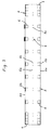
- Fig. 3
- einen gegenüber Fig. 1 und 2 alternativ ausgebildeten Wagenkasten, ebenfalls in der Draufsicht.
- Fig. 1
- a car body of a rail vehicle in perspective view,
- Fig. 2
- 1 in top view,
- Fig. 3
- an alternative to Fig. 1 and 2 car body, also in plan view.
Das Untergestell 1 des Wagenkastens weist einen mittleren Langträger 1a
auf, der als Kastenträger oder als Doppel-T-Träger ausgeführt sein kann. Dieser
mittlere Langträger 1a ist mit Querträgern 1b verbunden, die oberhalb hier
nicht gezeigter Laufwerke als Hauptquerträger gestaltet sind. Das Dach hat
ebenfalls einen bevorzugt als Kastenträger oder Doppel-T-Träger ausgebildeten
mittleren Langträger 3a, an dem Dachspanten 3b angeschlossen sind.
Der mittlere Langträger 1a des Untergestelles 1 und der mittlere Langträger
3a des Daches 3 können für eine Aufnahme von Aggregaten (elektrisch,
pneumatisch, hydraulisch, Klimakanäle) entsprechend ausgeführt sein. Die
portalartig ausgebildeten Stirnwände 4 des Wagenkastens ermöglichen den
Fahrgästen einen Durchgang zu benachbarten Wagen.The underframe 1 of the car body has a central
In Längsmitte des Wagenkastens ist eine vertikale Mittelwand 5 angeordnet,
die mit dem mittleren Langträger 1a des Untergestelles 1 und mit dem mittleren
Langträger 3a des Daches 3 kraftübertragend verbunden ist. Durch diese
tragende Mittelwand 5 werden beispielsweise über Mittelpufferkupplungen in
den mittleren Langträger 1a des Untergestelles 1 eingeleitete Kräfte in das
Dach 3 übertragen, wobei auch die Stirnwände 4 mitwirken. Die äußeren
Seitenwände 2 des Wagenkasten sind jedoch in die Kraftübertragung zwischen
Untergestell 1 und Dach 3 nicht einbezogen. Dadurch können die Seitenwände
2 jeweils eine Öffnung aufweisen, die sich soweit wie möglich in
Länge des Wagenkastens erstreckt.A
Wie aus den Fig. 1 und 2 ersichtlich ist, besteht die vertikale Mittelwand 5 aus
einzelnen Wandelementen 5a. Diese Wandelemente 5a sind in einem Abstand
zueinander angeordnet, der einen Durchgang 5b für die Fahrgäste bietet.
Die in die Inneneinrichtung des Fahrzeuges integrierten Wandelemente 5a
dienen jeweils der Befestigung von Fahrgastsitzen 6, die in Wagenlängsrichtung
angeordnet sind.As can be seen from FIGS. 1 and 2, the
Im Ausführungsbeispiel nach Fig. 3 besteht die vertikale Mittelwand 5 aus einzelnen
Säulen 5c. Auch in diesem Fall ist ein Durchgang 5b für die Fahrgäste
vorhanden. Die mittleren Säulen 5c sind vorzugsweise als Griffstangen für die
Fahrgäste ausgebildet. Die Fahrgastsitze 6 befinden sich an den äußeren
Seitenwänden 2 des Wagenkastens.3, the
Die äußeren Seitenwände 2 des Wagenkastens bestehen aus einander abwechselnden
Seitenwandfeldern 2b und breiten Türöffnungen 2a, die mit seitlich
bewegbaren Türflügeln 7 verschließbar sind. Wegen der besonders
schmalen Seitenwandfelder 2b und der erheblichen Breite der Türöffnungen
2a ist eine Anordnung vorgesehen, bei der sich die Türflügel 7 benachbarter
Türöffnungen 2a in ihrer geöffneten Stellung einander weitgehend überdecken
- siehe dazu speziell die zu Fig. 2 gehörende vergrößerte Darstellung. Die
Seitenwandfelder 2b können mit Fenstern versehen oder fensterlos sein, wobei
lediglich die Türflügel 7 Fenster beinhalten. Es empfiehlt sich, die Seitenwandfelder
2b aus faserverstärktem Kunststoff herzustellen und an ihrem oberen
Rand sowie an ihrem unteren Rand im Sinne einer Aufnahme von Längsschub
auszubilden. The
- 11
- UntergestellUnderframe
- 1a1a
- mittlerer Langträgermedium long girder
- 1b1b
- QuerträgerCross member
- 22nd
- äußere Seitenwandouter side wall
- 2a2a
- TüröffnungDoor opening
- 2b2 B
- SeitenwandfeldSidewall panel
- 33rd
- Dachtop, roof
- 3a3a
- mittlerer Langträgermedium long girder
- 3b3b
- DachspantenRoof frames
- 44th
- Stirnwand bzw. PortalBulkhead or portal
- 55
- vertikale Mittelwandvertical middle wall
- 5a5a
- einzelnes Wandelementsingle wall element
- 5b5b
- Durchgang für FahrgästePassage for passengers
- 5c5c
- einzelne Säulesingle pillar
- 66
- FahrgastsitzPassenger seat
- 77
- TürflügelDoor leaf
Claims (14)
Applications Claiming Priority (2)
| Application Number | Priority Date | Filing Date | Title |
|---|---|---|---|
| DE19955539 | 1999-11-18 | ||
| DE19955539A DE19955539A1 (en) | 1999-11-18 | 1999-11-18 | Car body of a rail vehicle for the transportation of people |
Publications (1)
| Publication Number | Publication Date |
|---|---|
| EP1103440A1 true EP1103440A1 (en) | 2001-05-30 |
Family
ID=7929510
Family Applications (1)
| Application Number | Title | Priority Date | Filing Date |
|---|---|---|---|
| EP00124488A Withdrawn EP1103440A1 (en) | 1999-11-18 | 2000-11-09 | Body of a carriage for railway passenger traffic |
Country Status (2)
| Country | Link |
|---|---|
| EP (1) | EP1103440A1 (en) |
| DE (1) | DE19955539A1 (en) |
Cited By (1)
| Publication number | Priority date | Publication date | Assignee | Title |
|---|---|---|---|---|
| EP2165907A1 (en) | 2008-09-22 | 2010-03-24 | Bombardier Transportation GmbH | Car body shell and method for retrofitting a car body |
Citations (5)
| Publication number | Priority date | Publication date | Assignee | Title |
|---|---|---|---|---|
| DE626595C (en) * | 1931-11-15 | 1936-02-28 | Christoph & Unmack Akt Ges | Vehicle, especially lightweight railway vehicle |
| DE647370C (en) * | 1933-01-18 | 1937-07-03 | Curt Stedefeld Dipl Ing | Railway car body |
| US4373447A (en) * | 1976-09-16 | 1983-02-15 | Schweizerische Lokomotiv Und Maschinenfabrik | Rail vehicle passenger body |
| US4543887A (en) * | 1984-02-01 | 1985-10-01 | Thrall Car Manufacturing Company | Center beam railroad freight car |
| EP0306584A1 (en) * | 1986-03-12 | 1989-03-15 | Sarl Technoforme | Superstructure for railway or road vehicles |
Family Cites Families (2)
| Publication number | Priority date | Publication date | Assignee | Title |
|---|---|---|---|---|
| DE19619212A1 (en) * | 1996-05-13 | 1997-11-20 | Duewag Ag | Car body of a rail vehicle |
| DE19736910A1 (en) * | 1997-08-25 | 1999-03-04 | Duewag Ag | Car body of a rail vehicle |
-
1999
- 1999-11-18 DE DE19955539A patent/DE19955539A1/en not_active Withdrawn
-
2000
- 2000-11-09 EP EP00124488A patent/EP1103440A1/en not_active Withdrawn
Patent Citations (5)
| Publication number | Priority date | Publication date | Assignee | Title |
|---|---|---|---|---|
| DE626595C (en) * | 1931-11-15 | 1936-02-28 | Christoph & Unmack Akt Ges | Vehicle, especially lightweight railway vehicle |
| DE647370C (en) * | 1933-01-18 | 1937-07-03 | Curt Stedefeld Dipl Ing | Railway car body |
| US4373447A (en) * | 1976-09-16 | 1983-02-15 | Schweizerische Lokomotiv Und Maschinenfabrik | Rail vehicle passenger body |
| US4543887A (en) * | 1984-02-01 | 1985-10-01 | Thrall Car Manufacturing Company | Center beam railroad freight car |
| EP0306584A1 (en) * | 1986-03-12 | 1989-03-15 | Sarl Technoforme | Superstructure for railway or road vehicles |
Cited By (1)
| Publication number | Priority date | Publication date | Assignee | Title |
|---|---|---|---|---|
| EP2165907A1 (en) | 2008-09-22 | 2010-03-24 | Bombardier Transportation GmbH | Car body shell and method for retrofitting a car body |
Also Published As
| Publication number | Publication date |
|---|---|
| DE19955539A1 (en) | 2001-05-31 |
Similar Documents
| Publication | Publication Date | Title |
|---|---|---|
| DE2642531C3 (en) | traction vehicle | |
| EP1781522B1 (en) | Climbing guard for railway vehicles | |
| DE4442368C2 (en) | Double-decker rail vehicle | |
| DE3911138C2 (en) | ||
| EP0616936A1 (en) | Articulated train | |
| DE19609995B4 (en) | End wall for lightweight rail vehicles, especially cab end wall for local rail vehicles | |
| EP0926036B1 (en) | Body of a railway vehicle | |
| EP0577938B1 (en) | Articulated powered railcar for railway traffic | |
| DE2711646C3 (en) | Articulated train for public transport, especially trams or underground trains | |
| DE2504966A1 (en) | HIGH RAILWAY TRANSPORT SYSTEM | |
| EP1103440A1 (en) | Body of a carriage for railway passenger traffic | |
| EP3504096B1 (en) | Articulated vehicle | |
| DE202018004330U1 (en) | Honeycomb as a construction principle for car bodies | |
| DE10053125A1 (en) | Rail vehicle with a modular body | |
| EP1008504B1 (en) | Vehicle body, especially end or front module or drivers cabin of a railway vehicle | |
| DE472685C (en) | Rail vehicle | |
| DE4309583C2 (en) | Lift installation in a multi-storey rail vehicle | |
| DE3504471A1 (en) | Articulated rail car for local-transport vehicles, in particular trams | |
| DE947677C (en) | Frames for motor vehicles, especially passenger cars | |
| EP0846606A1 (en) | Segmented shell construction with float mounted liner | |
| DE19714842B4 (en) | Partition for passenger coach, especially for cars of a local train | |
| EP0507109B1 (en) | Supporting and guiding device for the bearing of a central buffing sill in the undercarriage of a railway vehicle | |
| DE468407C (en) | Box framework for single-rail express train cars | |
| WO2021013450A1 (en) | Rail vehicle | |
| DE6911856U (en) | CARRIAGES FOR LIGHT RAILWAYS |
Legal Events
| Date | Code | Title | Description |
|---|---|---|---|
| PUAI | Public reference made under article 153(3) epc to a published international application that has entered the european phase |
Free format text: ORIGINAL CODE: 0009012 |
|
| AK | Designated contracting states |
Kind code of ref document: A1 Designated state(s): AT BE CH CY DE DK ES FI FR GB GR IE IT LI LU MC NL PT SE TR |
|
| AX | Request for extension of the european patent |
Free format text: AL;LT;LV;MK;RO;SI |
|
| AKX | Designation fees paid | ||
| REG | Reference to a national code |
Ref country code: DE Ref legal event code: 8566 |
|
| STAA | Information on the status of an ep patent application or granted ep patent |
Free format text: STATUS: THE APPLICATION IS DEEMED TO BE WITHDRAWN |
|
| 18D | Application deemed to be withdrawn |
Effective date: 20011201 |