EP1103339B1 - Drilling assembly for panel milling and drilling machines - Google Patents
Drilling assembly for panel milling and drilling machines Download PDFInfo
- Publication number
- EP1103339B1 EP1103339B1 EP00114207A EP00114207A EP1103339B1 EP 1103339 B1 EP1103339 B1 EP 1103339B1 EP 00114207 A EP00114207 A EP 00114207A EP 00114207 A EP00114207 A EP 00114207A EP 1103339 B1 EP1103339 B1 EP 1103339B1
- Authority
- EP
- European Patent Office
- Prior art keywords
- drilling
- coupled
- mandrel
- drilling assembly
- slotted shaft
- Prior art date
- Legal status (The legal status is an assumption and is not a legal conclusion. Google has not performed a legal analysis and makes no representation as to the accuracy of the status listed.)
- Expired - Lifetime
Links
- 238000005553 drilling Methods 0.000 title claims description 65
- 238000003801 milling Methods 0.000 title claims description 8
- 230000008878 coupling Effects 0.000 description 3
- 238000010168 coupling process Methods 0.000 description 3
- 238000005859 coupling reaction Methods 0.000 description 3
- 238000003754 machining Methods 0.000 description 3
- 230000002860 competitive effect Effects 0.000 description 1
- 230000004048 modification Effects 0.000 description 1
- 238000012986 modification Methods 0.000 description 1
Images


Classifications
-
- B—PERFORMING OPERATIONS; TRANSPORTING
- B23—MACHINE TOOLS; METAL-WORKING NOT OTHERWISE PROVIDED FOR
- B23Q—DETAILS, COMPONENTS, OR ACCESSORIES FOR MACHINE TOOLS, e.g. ARRANGEMENTS FOR COPYING OR CONTROLLING; MACHINE TOOLS IN GENERAL CHARACTERISED BY THE CONSTRUCTION OF PARTICULAR DETAILS OR COMPONENTS; COMBINATIONS OR ASSOCIATIONS OF METAL-WORKING MACHINES, NOT DIRECTED TO A PARTICULAR RESULT
- B23Q1/00—Members which are comprised in the general build-up of a form of machine, particularly relatively large fixed members
- B23Q1/25—Movable or adjustable work or tool supports
- B23Q1/26—Movable or adjustable work or tool supports characterised by constructional features relating to the co-operation of relatively movable members; Means for preventing relative movement of such members
- B23Q1/28—Means for securing sliding members in any desired position
-
- B—PERFORMING OPERATIONS; TRANSPORTING
- B23—MACHINE TOOLS; METAL-WORKING NOT OTHERWISE PROVIDED FOR
- B23B—TURNING; BORING
- B23B39/00—General-purpose boring or drilling machines or devices; Sets of boring and/or drilling machines
- B23B39/16—Drilling machines with a plurality of working-spindles; Drilling automatons
- B23B39/161—Drilling machines with a plurality of working-spindles; Drilling automatons with parallel work spindles
- B23B39/162—Drilling machines with a plurality of working-spindles; Drilling automatons with parallel work spindles having gear transmissions
-
- B—PERFORMING OPERATIONS; TRANSPORTING
- B23—MACHINE TOOLS; METAL-WORKING NOT OTHERWISE PROVIDED FOR
- B23Q—DETAILS, COMPONENTS, OR ACCESSORIES FOR MACHINE TOOLS, e.g. ARRANGEMENTS FOR COPYING OR CONTROLLING; MACHINE TOOLS IN GENERAL CHARACTERISED BY THE CONSTRUCTION OF PARTICULAR DETAILS OR COMPONENTS; COMBINATIONS OR ASSOCIATIONS OF METAL-WORKING MACHINES, NOT DIRECTED TO A PARTICULAR RESULT
- B23Q1/00—Members which are comprised in the general build-up of a form of machine, particularly relatively large fixed members
- B23Q1/25—Movable or adjustable work or tool supports
- B23Q1/26—Movable or adjustable work or tool supports characterised by constructional features relating to the co-operation of relatively movable members; Means for preventing relative movement of such members
-
- B—PERFORMING OPERATIONS; TRANSPORTING
- B23—MACHINE TOOLS; METAL-WORKING NOT OTHERWISE PROVIDED FOR
- B23Q—DETAILS, COMPONENTS, OR ACCESSORIES FOR MACHINE TOOLS, e.g. ARRANGEMENTS FOR COPYING OR CONTROLLING; MACHINE TOOLS IN GENERAL CHARACTERISED BY THE CONSTRUCTION OF PARTICULAR DETAILS OR COMPONENTS; COMBINATIONS OR ASSOCIATIONS OF METAL-WORKING MACHINES, NOT DIRECTED TO A PARTICULAR RESULT
- B23Q5/00—Driving or feeding mechanisms; Control arrangements therefor
- B23Q5/02—Driving main working members
- B23Q5/04—Driving main working members rotary shafts, e.g. working-spindles
- B23Q5/043—Accessories for spindle drives
- B23Q5/045—Angle drives
-
- B—PERFORMING OPERATIONS; TRANSPORTING
- B23—MACHINE TOOLS; METAL-WORKING NOT OTHERWISE PROVIDED FOR
- B23Q—DETAILS, COMPONENTS, OR ACCESSORIES FOR MACHINE TOOLS, e.g. ARRANGEMENTS FOR COPYING OR CONTROLLING; MACHINE TOOLS IN GENERAL CHARACTERISED BY THE CONSTRUCTION OF PARTICULAR DETAILS OR COMPONENTS; COMBINATIONS OR ASSOCIATIONS OF METAL-WORKING MACHINES, NOT DIRECTED TO A PARTICULAR RESULT
- B23Q5/00—Driving or feeding mechanisms; Control arrangements therefor
- B23Q5/22—Feeding members carrying tools or work
- B23Q5/26—Fluid-pressure drives
- B23Q5/261—Fluid-pressure drives for spindles
Definitions
- the present invention relates to a drilling assembly, specifically designed for panel milling and drilling machines.
- panel milling and drilling machines conventionally comprise a drilling assembly, including a plurality of mandrels for performing a vertical drilling and mandrels for performing a horizontal drilling, said mandrels being very complex construction-wise since they must perform a series of intricate movements for assuming their proper operating positions.
- the aim of the present invention is to overcome the above mentioned drawbacks, by providing a drilling assembly, specifically designed for panel milling and drilling machines, allowing to firmly and safely locate the operating mandrels thereof, thereby providing a very good machining quality.
- a main object of the present invention is to provide such a drilling assembly including very simple means for locking the operating mandrels in their set operating positions.
- Another object of the present invention is to provide such a drilling assembly which, owing to its peculiar constructional features, is very reliable and safe in operation.
- Yet another object of the present invention is to provide such a drilling assembly which can be easily made starting from easily available elements and materials and which, moreover, is very competitive from a mere economic standpoint.
- a drilling assembly specifically designed for panel, milling and drilling machines, comprising a plurality of vertical drilling mandrels and horizontal drilling mandrels, characterized in that each said vertical drilling mandrels comprises a slotted shaft slidably engaged with a driving gear.
- the slotted shaft is coupled, at a bottom portion thereof, to a drill holding mandrel and, at a top portion thereof, to an expanding piston for removably locking the drill holding mandrel at a lowered working position thereof.
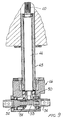
- the drilling assembly specifically designed for panel milling and drilling machines, which has been generally indicated by the reference number 1, comprises a plurality of vertical drilling mandrels 2 and at least a horizontal drilling mandrel 3.
- Each vertical drilling mandrel 2 comprises, in turn, a slotted or splined shaft 10, which is slidably engaged inside a driving gear 11, the latter being coupled to a kinematic gear chain 12 taking the drive from a driving motor (not specifically shown).
- the splined or slotted shaft 10, which can slide with respect to the driving gear 11, is coupled, at its bottom portion, through a vertical shaft or spindle 15, which can turn inside a first bushing 16, with a drill holding mandrel 17.
- the splined or slotted shaft 10 is coupled to an expanding piston 20 which, by a piston rod 21, is coupled to a driving cylinder 22 provided for driving the vertical drilling mandrel.
- the expanding piston is adapted to slide through a first vertical sleeve 30 which, at the bottom portion thereof, on the side of the driving gear 11, is provided with an enlarged portion 31.
- the expanding piston 20 comprises a piston body 32 coupled to the splined shaft, ending with a conical tapering portion 33 encompassing a guide 34 in which a counter-conic element 35 can be engaged, which counter-conic element is coupled to the piston rod 21 and delimiting, in combination with a further conical tapering portion 33, a groove in which a split ring 37 is engaged.
- the split ring 37 will be radially expanded, to engage in a locked manner in the shoulder 38 defined between the first sleeve 30 and said enlarged portion 31.
- Said locking will prevent the pushing force affecting the vertical drilling drill, to cause the vertical mandrel to be raised again during a drilling operation, thereby said mandrel will be firmly held in its set position.
- the mentioned mandrel can be raised again since the piston rod 21, by recovering the counter-conic element 35 to its starting position, will allow the split ring 37 to radially contract, thereby allowing in turn the expanding piston 20 to be raised again.
- the horizontal drilling mandrel as shown, is provided with a second slotted or splined shaft 40, also slidably engaged with one of the driving gears, indicated by the reference number 13, included in the provided gear chain.
- Said second slotted or splined shaft 40 is coupled, at the top thereof to a coupling body 41, for coupling to a second piston rod 42 in turn connected to a horizontal drilling cylinder 43.
- the splined shaft 40 is coupled to a driving shaft 44 which can turn inside a second bushing 45 which, at the bottom thereof, is coupled to a horizontal drilling head 46.
- the bushing 45 is provided with a flat portion 47 therewith is engaged a tempered pin 48 provided for stopping the lowering movement of the horizontal drilling mandrel, thereby allowing a very stable position to be obtained.
- the horizontal drilling head 46 as is shown in a more detailed manner in Figure 9, is provided with a conical gear 50, coupled to the driving shaft 44, and meshing with a second conic or bevel gear 51.
- a horizontal drilling mandrel 52 which is rotatably supported by the drilling head and is provided with an end-piece 53 which is in turn supported by a supporting nut 54.
- the engagement of the pin and of the cut-out will operate as a guide element to prevent any rotary movements against the vertical axis of the horizontal drilling head.
- the used materials, as well as the contingent size and shapes can be any, depending on requirements.
Landscapes
- Engineering & Computer Science (AREA)
- Mechanical Engineering (AREA)
- Drilling And Boring (AREA)
- Drilling Tools (AREA)
Description
- The present invention relates to a drilling assembly, specifically designed for panel milling and drilling machines.
- As is known, panel milling and drilling machines conventionally comprise a drilling assembly, including a plurality of mandrels for performing a vertical drilling and mandrels for performing a horizontal drilling, said mandrels being very complex construction-wise since they must perform a series of intricate movements for assuming their proper operating positions.
- Another problem is that of the location stability of the mandrels which, in the prior art machine, (see, for example, DE-19829814-A), is very difficult to achieve.
- Thus, prior machines of the above mentioned type frequently provide a poor machining.
- Accordingly, the aim of the present invention is to overcome the above mentioned drawbacks, by providing a drilling assembly, specifically designed for panel milling and drilling machines, allowing to firmly and safely locate the operating mandrels thereof, thereby providing a very good machining quality.
- Within the scope of the above mentioned aim, a main object of the present invention is to provide such a drilling assembly including very simple means for locking the operating mandrels in their set operating positions.
- Another object of the present invention is to provide such a drilling assembly which, owing to its peculiar constructional features, is very reliable and safe in operation.
- Yet another object of the present invention is to provide such a drilling assembly which can be easily made starting from easily available elements and materials and which, moreover, is very competitive from a mere economic standpoint.
- According to one aspect of the present invention, the above mentioned aim and objects, as well as yet other objects, which will become more apparent hereinafter, are achieved by a drilling assembly specifically designed for panel, milling and drilling machines, comprising a plurality of vertical drilling mandrels and horizontal drilling mandrels, characterized in that each said vertical drilling mandrels comprises a slotted shaft slidably engaged with a driving gear.
- The slotted shaft, moreover, is coupled, at a bottom portion thereof, to a drill holding mandrel and, at a top portion thereof, to an expanding piston for removably locking the drill holding mandrel at a lowered working position thereof.
- Further characteristics and advantages of the present invention will become more apparent hereinafter from the following detailed disclosure of a preferred, though not exclusive, embodiment of a drilling assembly specifically designed for panel milling and drilling machines, and being illustrated, by way of an indicative, but not limitative, example in the figures of the accompanying drawings, where:
- Figure 1 is a schematic exploded perspective view illustrating a vertical drilling mandrel;
- Figure 2 illustrates a further schematic exploded perspective view of a horizontal drilling mandrel;
- Figure 3 is a cross-sectional view illustrating a vertical drilling mandrel in a rest condition thereof;
- Figure 4 illustrates a vertical drilling mandrel in an working position thereof;
- Figure 5 is a schematic cross-sectional view illustrating the expanding piston associated with the vertical drilling mandrel, in a rest or stand-by condition thereof;
- Figure 6 is further cross-sectional view illustrating the expanding piston and vertical drilling mandrel in a working position thereof;
- Figure 7 is a further schematic cross-sectional view illustrating the horizontal drilling mandrel in a rest or stand-by position thereof;
- Figure 8 illustrates the horizontal drilling mandrel in a working position thereof; and
- Figure 9 is a cross-sectional view illustrating a detail of the horizontal drill holding mandrel.
-
- With reference to the number references of the above mentioned figures, the drilling assembly, specifically designed for panel milling and drilling machines, which has been generally indicated by the
reference number 1, comprises a plurality ofvertical drilling mandrels 2 and at least ahorizontal drilling mandrel 3. - Each
vertical drilling mandrel 2 comprises, in turn, a slotted orsplined shaft 10, which is slidably engaged inside adriving gear 11, the latter being coupled to akinematic gear chain 12 taking the drive from a driving motor (not specifically shown). - The splined or slotted
shaft 10, which can slide with respect to thedriving gear 11, is coupled, at its bottom portion, through a vertical shaft orspindle 15, which can turn inside afirst bushing 16, with adrill holding mandrel 17. - At the top thereof, the splined or slotted
shaft 10 is coupled to an expandingpiston 20 which, by apiston rod 21, is coupled to a drivingcylinder 22 provided for driving the vertical drilling mandrel. - The expanding piston is adapted to slide through a first
vertical sleeve 30 which, at the bottom portion thereof, on the side of thedriving gear 11, is provided with an enlargedportion 31. - As shown, the expanding
piston 20 comprises apiston body 32 coupled to the splined shaft, ending with aconical tapering portion 33 encompassing aguide 34 in which acounter-conic element 35 can be engaged, which counter-conic element is coupled to thepiston rod 21 and delimiting, in combination with a furtherconical tapering portion 33, a groove in which asplit ring 37 is engaged. - Thus, as the vertical drilling mandrel is caused to be lowered, said
counter-conic element 35 will provide a pushing force. - As the expanding
piston 20 is arranged at the enlargedportion 31, thesplit ring 37 will be radially expanded, to engage in a locked manner in theshoulder 38 defined between thefirst sleeve 30 and said enlargedportion 31. - Said locking will prevent the pushing force affecting the vertical drilling drill, to cause the vertical mandrel to be raised again during a drilling operation, thereby said mandrel will be firmly held in its set position.
- At the completion of the drilling operation, on the other hand, the mentioned mandrel can be raised again since the
piston rod 21, by recovering thecounter-conic element 35 to its starting position, will allow thesplit ring 37 to radially contract, thereby allowing in turn the expandingpiston 20 to be raised again. - The horizontal drilling mandrel, as shown, is provided with a second slotted or
splined shaft 40, also slidably engaged with one of the driving gears, indicated by thereference number 13, included in the provided gear chain. - Said second slotted or
splined shaft 40 is coupled, at the top thereof to acoupling body 41, for coupling to asecond piston rod 42 in turn connected to ahorizontal drilling cylinder 43. - At the bottom thereof the
splined shaft 40 is coupled to a drivingshaft 44 which can turn inside asecond bushing 45 which, at the bottom thereof, is coupled to ahorizontal drilling head 46. - The
bushing 45 is provided with aflat portion 47 therewith is engaged a temperedpin 48 provided for stopping the lowering movement of the horizontal drilling mandrel, thereby allowing a very stable position to be obtained. - The
horizontal drilling head 46, as is shown in a more detailed manner in Figure 9, is provided with aconical gear 50, coupled to the drivingshaft 44, and meshing with a second conic orbevel gear 51. - The latter is keyed on a
horizontal drilling mandrel 52, which is rotatably supported by the drilling head and is provided with an end-piece 53 which is in turn supported by a supportingnut 54. - With the above disclosed arrangement, as the horizontal drilling mandrel is lowered to a working position thereof, the engagement of the
pin 48 and top end portion of the cut-out 47 will provide a very stable coupling eliminating any clearances, thereby the machine can perform a very accurate machining. - Moreover, the engagement of the pin and of the cut-out will operate as a guide element to prevent any rotary movements against the vertical axis of the horizontal drilling head.
- From the above disclosure it should be apparent that the invention fully achieves the intended aim and objects.
- In particular, the fact is to be pointed out that a drilling assembly has been provided which, by very simple means, allows to firmly locate at their working positions both the vertical mandrels and the horizontal mandrels.
- The invention as disclosed is susceptible to several modifications and variations, all of which will come within the invention scope, as defined in the appended claims.
- Moreover, all of the constructional details can be replaced by other technically equivalent elements.
- In practicing the invention, the used materials, as well as the contingent size and shapes, can be any, depending on requirements.
Claims (9)
- A drilling assembly, specifically designed for panel milling and drilling machines, comprising a plurality of vertical drilling mandrels (2) and horizontal drilling mandrels (3), whereby each said vertical drilling mandrels (2) comprises a slotted shaft (10) slidably engaged with a driving gear (11) and that said slotted shaft is coupled, at a bottom portion thereof, to a drill holding mandrel (17), characterized in that said slotted shaft is coupled at a top portion thereof, to an expanding piston (20) for removably locking the drill holding mandrel at a lowered or working position thereof.
- A drilling assembly, according to the preceding claim, characterized in that said slotted shaft (10) is coupled, at a bottom portion thereof, to a shaft (15) which is rotatably supported by a first bottom bushing (16) also supporting said drill holding mandrel (17).
- A drilling assembly, according to one of the preceding claims, characterized in that said expanding piston (20) comprises a piston body (32) coupled to said slotted shaft and engageable in a first top sleeve (30), and that said expanding piston is coupled, at a top portion thereof to a piston rod (21) in turn coupled to a first driving cylinder (22).
- A drilling assembly, according to claim 3, characterized in that said sleeve (30) is provided, at a bottom end portion thereof, with a locking enlarged portion (31) for locking said expanding piston.
- A drilling assembly, according to one of the preceding claims, characterized in that the expanding piston comprises a piston body coupled to the slotted shaft and ending with a conical tapering portion (33), and that, inside said conical tapering portion is provided a guide seat of a counter-conic element (35) delimiting, with said conic tapering portion, a groove in which a split ring (37) is engaged, said split ring being adapted to be radially expanded in said enlarged portion (31) under a pushing by said piston rod, a pulling force on said counter-conic elment causing a partial disengaging of the counter-conic element from said conic tapering portion, thereby causing said split ring to be radially contracted and disengaged from said enlarged portion.
- A drilling assembly, according to one of the preceding claims, characterized in that said driving gear meshes with a gear chain coupled to a motor.
- A drilling assembly, according to one of the preceding claims, characterized in that said horizontal drilling mandrel (3) is provided with a slotted shaft (40) coupled, at a bottom portion thereof, to a drive shaft (44) rotatably supported inside a second bottom bushing (45) supporting the horizontal drilling head, and that the second bottom bushing is provided with a flat surface portion and therein is engaged a tempered pin (48) designed for operating as a limit element for the locating, during a working operation, of said horizontal drilling mandrel.
- A drilling assembly, according to claim 7, characterized in that the second slotted shaft (40) is coupled, at the top portion thereof, to a body in turn coupled, through a second stem (42), to a horizontal drilling mandrel driving cylinder (43).
- A drilling assembly, according to one of the preceding claims 7 or 8, characterized in that said slotted shaft (40) is coupled to a first conical gear (50), rotatably supported by said head and operatively coupled to a drill holding mandrel (52).
Applications Claiming Priority (2)
| Application Number | Priority Date | Filing Date | Title |
|---|---|---|---|
| IT1999MI002447A IT1314085B1 (en) | 1999-11-23 | 1999-11-23 | DRILLING GROUP PARTICULARLY DESIGNED FOR MILLING AND PANEL DRILLING MACHINES. |
| ITMI992447 | 1999-11-23 |
Publications (2)
| Publication Number | Publication Date |
|---|---|
| EP1103339A1 EP1103339A1 (en) | 2001-05-30 |
| EP1103339B1 true EP1103339B1 (en) | 2004-02-18 |
Family
ID=11384006
Family Applications (1)
| Application Number | Title | Priority Date | Filing Date |
|---|---|---|---|
| EP00114207A Expired - Lifetime EP1103339B1 (en) | 1999-11-23 | 2000-07-03 | Drilling assembly for panel milling and drilling machines |
Country Status (3)
| Country | Link |
|---|---|
| EP (1) | EP1103339B1 (en) |
| DE (1) | DE60008341T2 (en) |
| IT (1) | IT1314085B1 (en) |
Cited By (1)
| Publication number | Priority date | Publication date | Assignee | Title |
|---|---|---|---|---|
| WO2022194766A1 (en) * | 2021-03-15 | 2022-09-22 | Benz GmbH Werkzeugsysteme | Spindle assembly |
Families Citing this family (3)
| Publication number | Priority date | Publication date | Assignee | Title |
|---|---|---|---|---|
| ITTV20020079A1 (en) * | 2002-07-09 | 2004-01-09 | Luca Toncelli | SLIDE OR SPINDLE HOLDER FOR NUMERICALLY CONTROLLED MACHINES |
| DE102009050476B4 (en) * | 2009-10-23 | 2015-06-18 | Airbus S.A.S. | drilling |
| CN115415854B (en) * | 2022-09-16 | 2024-04-12 | 山东圣利锻造有限公司 | Drilling device with drilling position trimming function for machining |
Family Cites Families (3)
| Publication number | Priority date | Publication date | Assignee | Title |
|---|---|---|---|---|
| JPS5827048B2 (en) * | 1974-03-03 | 1983-06-07 | ミヤガワコウギヨウ カブシキガイシヤ | H |
| DE4016480C2 (en) * | 1990-05-22 | 1994-07-14 | Gustav Weeke Maschinenbau Gmbh | Spindle unit for a drilling and milling machine |
| IT1293277B1 (en) * | 1997-07-30 | 1999-02-16 | Scm Group Autec Division Spa | ARCHITECTURE FOR DRILLING UNIT. |
-
1999
- 1999-11-23 IT IT1999MI002447A patent/IT1314085B1/en active
-
2000
- 2000-07-03 DE DE60008341T patent/DE60008341T2/en not_active Expired - Fee Related
- 2000-07-03 EP EP00114207A patent/EP1103339B1/en not_active Expired - Lifetime
Cited By (1)
| Publication number | Priority date | Publication date | Assignee | Title |
|---|---|---|---|---|
| WO2022194766A1 (en) * | 2021-03-15 | 2022-09-22 | Benz GmbH Werkzeugsysteme | Spindle assembly |
Also Published As
| Publication number | Publication date |
|---|---|
| IT1314085B1 (en) | 2002-12-04 |
| EP1103339A1 (en) | 2001-05-30 |
| DE60008341T2 (en) | 2009-10-01 |
| ITMI992447A1 (en) | 2001-05-23 |
| ITMI992447A0 (en) | 1999-11-23 |
| DE60008341D1 (en) | 2004-03-25 |
Similar Documents
| Publication | Publication Date | Title |
|---|---|---|
| US5533846A (en) | Universal milling and drilling machine | |
| US7806637B2 (en) | Positive-feed machine tool permitting a clearing operation | |
| EP1334846B1 (en) | Bead releasing and tire disassembling group in a tire assembling-disassembling machine | |
| US4657453A (en) | Milling device with universal gear and automatic indexation | |
| US2952169A (en) | Indexing multiple tool holder | |
| KR20190000949A (en) | Drilling machine | |
| EP1103339A1 (en) | Drilling assembly for panel milling and drilling machines | |
| US7413036B2 (en) | Sub drilling sub | |
| CN107598210B (en) | The continuously punched assembly line on workpiece | |
| CN120663125A (en) | Integrated machine for processing blind holes, key grooves and anti-theft buckles of oil field perforating gun double heads and processing method | |
| US2647407A (en) | Machine tool spindle construction | |
| US2216988A (en) | Depth stop for countersinking, boring, drilling, and similar devices | |
| CN106112133B (en) | A kind of vertical gear hobber | |
| CN113798402A (en) | Riveting tool and method for flange nut | |
| US3496587A (en) | Drill mechanism for sponge iron reactors and the like | |
| CN205888146U (en) | Link anchor drilling special plane | |
| US2554207A (en) | Machine tool | |
| US1549241A (en) | Drilling and tapping machine | |
| JP4143492B2 (en) | Rotary cutting device | |
| KR200392104Y1 (en) | Automatic Tapping Apparatus For Sintered Body | |
| CN223419099U (en) | High-precision hole grinding equipment | |
| KR101432299B1 (en) | Control tool for CNC lathe | |
| CN218170941U (en) | Perforating device for construction | |
| JP2007144578A (en) | Attachment-type head for machine tool and machine tool | |
| EP0661133B1 (en) | A machining unit with a series of selectively operable tool-carrier mandrels |
Legal Events
| Date | Code | Title | Description |
|---|---|---|---|
| PUAI | Public reference made under article 153(3) epc to a published international application that has entered the european phase |
Free format text: ORIGINAL CODE: 0009012 |
|
| AK | Designated contracting states |
Kind code of ref document: A1 Designated state(s): DE ES FR GB |
|
| AX | Request for extension of the european patent |
Free format text: AL;LT;LV;MK;RO;SI |
|
| 17P | Request for examination filed |
Effective date: 20010919 |
|
| AKX | Designation fees paid |
Free format text: DE ES FR GB |
|
| GRAP | Despatch of communication of intention to grant a patent |
Free format text: ORIGINAL CODE: EPIDOSNIGR1 |
|
| GRAS | Grant fee paid |
Free format text: ORIGINAL CODE: EPIDOSNIGR3 |
|
| GRAA | (expected) grant |
Free format text: ORIGINAL CODE: 0009210 |
|
| AK | Designated contracting states |
Kind code of ref document: B1 Designated state(s): DE ES FR GB |
|
| PG25 | Lapsed in a contracting state [announced via postgrant information from national office to epo] |
Ref country code: FR Free format text: LAPSE BECAUSE OF FAILURE TO SUBMIT A TRANSLATION OF THE DESCRIPTION OR TO PAY THE FEE WITHIN THE PRESCRIBED TIME-LIMIT Effective date: 20040218 |
|
| REG | Reference to a national code |
Ref country code: GB Ref legal event code: FG4D |
|
| REF | Corresponds to: |
Ref document number: 60008341 Country of ref document: DE Date of ref document: 20040325 Kind code of ref document: P |
|
| PG25 | Lapsed in a contracting state [announced via postgrant information from national office to epo] |
Ref country code: ES Free format text: LAPSE BECAUSE OF FAILURE TO SUBMIT A TRANSLATION OF THE DESCRIPTION OR TO PAY THE FEE WITHIN THE PRESCRIBED TIME-LIMIT Effective date: 20040529 |
|
| PG25 | Lapsed in a contracting state [announced via postgrant information from national office to epo] |
Ref country code: GB Free format text: LAPSE BECAUSE OF NON-PAYMENT OF DUE FEES Effective date: 20040703 |
|
| PLBE | No opposition filed within time limit |
Free format text: ORIGINAL CODE: 0009261 |
|
| STAA | Information on the status of an ep patent application or granted ep patent |
Free format text: STATUS: NO OPPOSITION FILED WITHIN TIME LIMIT |
|
| EN | Fr: translation not filed | ||
| 26N | No opposition filed |
Effective date: 20041119 |
|
| GBPC | Gb: european patent ceased through non-payment of renewal fee |
Effective date: 20040703 |
|
| PGFP | Annual fee paid to national office [announced via postgrant information from national office to epo] |
Ref country code: DE Payment date: 20090828 Year of fee payment: 10 |
|
| PG25 | Lapsed in a contracting state [announced via postgrant information from national office to epo] |
Ref country code: DE Free format text: LAPSE BECAUSE OF NON-PAYMENT OF DUE FEES Effective date: 20110201 |
|
| REG | Reference to a national code |
Ref country code: DE Ref legal event code: R119 Ref document number: 60008341 Country of ref document: DE Effective date: 20110201 |