EP1103306A1 - Plastic chip separator - Google Patents
Plastic chip separator Download PDFInfo
- Publication number
- EP1103306A1 EP1103306A1 EP00909781A EP00909781A EP1103306A1 EP 1103306 A1 EP1103306 A1 EP 1103306A1 EP 00909781 A EP00909781 A EP 00909781A EP 00909781 A EP00909781 A EP 00909781A EP 1103306 A1 EP1103306 A1 EP 1103306A1
- Authority
- EP
- European Patent Office
- Prior art keywords
- plastic
- plastic pieces
- collecting
- partition walls
- electrostatic
- Prior art date
- Legal status (The legal status is an assumption and is not a legal conclusion. Google has not performed a legal analysis and makes no representation as to the accuracy of the status listed.)
- Granted
Links
Images


Classifications
-
- B—PERFORMING OPERATIONS; TRANSPORTING
- B03—SEPARATION OF SOLID MATERIALS USING LIQUIDS OR USING PNEUMATIC TABLES OR JIGS; MAGNETIC OR ELECTROSTATIC SEPARATION OF SOLID MATERIALS FROM SOLID MATERIALS OR FLUIDS; SEPARATION BY HIGH-VOLTAGE ELECTRIC FIELDS
- B03C—MAGNETIC OR ELECTROSTATIC SEPARATION OF SOLID MATERIALS FROM SOLID MATERIALS OR FLUIDS; SEPARATION BY HIGH-VOLTAGE ELECTRIC FIELDS
- B03C7/00—Separating solids from solids by electrostatic effect
- B03C7/02—Separators
- B03C7/06—Separators with cylindrical material carriers
-
- B—PERFORMING OPERATIONS; TRANSPORTING
- B03—SEPARATION OF SOLID MATERIALS USING LIQUIDS OR USING PNEUMATIC TABLES OR JIGS; MAGNETIC OR ELECTROSTATIC SEPARATION OF SOLID MATERIALS FROM SOLID MATERIALS OR FLUIDS; SEPARATION BY HIGH-VOLTAGE ELECTRIC FIELDS
- B03C—MAGNETIC OR ELECTROSTATIC SEPARATION OF SOLID MATERIALS FROM SOLID MATERIALS OR FLUIDS; SEPARATION BY HIGH-VOLTAGE ELECTRIC FIELDS
- B03C7/00—Separating solids from solids by electrostatic effect
- B03C7/006—Charging without electricity supply, e.g. by tribo-electricity or pyroelectricity
-
- B—PERFORMING OPERATIONS; TRANSPORTING
- B29—WORKING OF PLASTICS; WORKING OF SUBSTANCES IN A PLASTIC STATE IN GENERAL
- B29B—PREPARATION OR PRETREATMENT OF THE MATERIAL TO BE SHAPED; MAKING GRANULES OR PREFORMS; RECOVERY OF PLASTICS OR OTHER CONSTITUENTS OF WASTE MATERIAL CONTAINING PLASTICS
- B29B17/00—Recovery of plastics or other constituents of waste material containing plastics
- B29B17/02—Separating plastics from other materials
-
- B—PERFORMING OPERATIONS; TRANSPORTING
- B29—WORKING OF PLASTICS; WORKING OF SUBSTANCES IN A PLASTIC STATE IN GENERAL
- B29B—PREPARATION OR PRETREATMENT OF THE MATERIAL TO BE SHAPED; MAKING GRANULES OR PREFORMS; RECOVERY OF PLASTICS OR OTHER CONSTITUENTS OF WASTE MATERIAL CONTAINING PLASTICS
- B29B17/00—Recovery of plastics or other constituents of waste material containing plastics
- B29B17/02—Separating plastics from other materials
- B29B2017/0203—Separating plastics from plastics
-
- B—PERFORMING OPERATIONS; TRANSPORTING
- B29—WORKING OF PLASTICS; WORKING OF SUBSTANCES IN A PLASTIC STATE IN GENERAL
- B29B—PREPARATION OR PRETREATMENT OF THE MATERIAL TO BE SHAPED; MAKING GRANULES OR PREFORMS; RECOVERY OF PLASTICS OR OTHER CONSTITUENTS OF WASTE MATERIAL CONTAINING PLASTICS
- B29B17/00—Recovery of plastics or other constituents of waste material containing plastics
- B29B17/02—Separating plastics from other materials
- B29B2017/0213—Specific separating techniques
- B29B2017/0262—Specific separating techniques using electrical caracteristics
- B29B2017/0265—Electrostatic separation
-
- B—PERFORMING OPERATIONS; TRANSPORTING
- B29—WORKING OF PLASTICS; WORKING OF SUBSTANCES IN A PLASTIC STATE IN GENERAL
- B29K—INDEXING SCHEME ASSOCIATED WITH SUBCLASSES B29B, B29C OR B29D, RELATING TO MOULDING MATERIALS OR TO MATERIALS FOR MOULDS, REINFORCEMENTS, FILLERS OR PREFORMED PARTS, e.g. INSERTS
- B29K2023/00—Use of polyalkenes or derivatives thereof as moulding material
- B29K2023/04—Polymers of ethylene
- B29K2023/06—PE, i.e. polyethylene
-
- B—PERFORMING OPERATIONS; TRANSPORTING
- B29—WORKING OF PLASTICS; WORKING OF SUBSTANCES IN A PLASTIC STATE IN GENERAL
- B29K—INDEXING SCHEME ASSOCIATED WITH SUBCLASSES B29B, B29C OR B29D, RELATING TO MOULDING MATERIALS OR TO MATERIALS FOR MOULDS, REINFORCEMENTS, FILLERS OR PREFORMED PARTS, e.g. INSERTS
- B29K2023/00—Use of polyalkenes or derivatives thereof as moulding material
- B29K2023/10—Polymers of propylene
- B29K2023/12—PP, i.e. polypropylene
-
- B—PERFORMING OPERATIONS; TRANSPORTING
- B29—WORKING OF PLASTICS; WORKING OF SUBSTANCES IN A PLASTIC STATE IN GENERAL
- B29K—INDEXING SCHEME ASSOCIATED WITH SUBCLASSES B29B, B29C OR B29D, RELATING TO MOULDING MATERIALS OR TO MATERIALS FOR MOULDS, REINFORCEMENTS, FILLERS OR PREFORMED PARTS, e.g. INSERTS
- B29K2025/00—Use of polymers of vinyl-aromatic compounds or derivatives thereof as moulding material
-
- B—PERFORMING OPERATIONS; TRANSPORTING
- B29—WORKING OF PLASTICS; WORKING OF SUBSTANCES IN A PLASTIC STATE IN GENERAL
- B29K—INDEXING SCHEME ASSOCIATED WITH SUBCLASSES B29B, B29C OR B29D, RELATING TO MOULDING MATERIALS OR TO MATERIALS FOR MOULDS, REINFORCEMENTS, FILLERS OR PREFORMED PARTS, e.g. INSERTS
- B29K2027/00—Use of polyvinylhalogenides or derivatives thereof as moulding material
- B29K2027/06—PVC, i.e. polyvinylchloride
-
- B—PERFORMING OPERATIONS; TRANSPORTING
- B29—WORKING OF PLASTICS; WORKING OF SUBSTANCES IN A PLASTIC STATE IN GENERAL
- B29K—INDEXING SCHEME ASSOCIATED WITH SUBCLASSES B29B, B29C OR B29D, RELATING TO MOULDING MATERIALS OR TO MATERIALS FOR MOULDS, REINFORCEMENTS, FILLERS OR PREFORMED PARTS, e.g. INSERTS
- B29K2033/00—Use of polymers of unsaturated acids or derivatives thereof as moulding material
- B29K2033/04—Polymers of esters
- B29K2033/12—Polymers of methacrylic acid esters, e.g. PMMA, i.e. polymethylmethacrylate
-
- B—PERFORMING OPERATIONS; TRANSPORTING
- B29—WORKING OF PLASTICS; WORKING OF SUBSTANCES IN A PLASTIC STATE IN GENERAL
- B29K—INDEXING SCHEME ASSOCIATED WITH SUBCLASSES B29B, B29C OR B29D, RELATING TO MOULDING MATERIALS OR TO MATERIALS FOR MOULDS, REINFORCEMENTS, FILLERS OR PREFORMED PARTS, e.g. INSERTS
- B29K2705/00—Use of metals, their alloys or their compounds, for preformed parts, e.g. for inserts
-
- Y—GENERAL TAGGING OF NEW TECHNOLOGICAL DEVELOPMENTS; GENERAL TAGGING OF CROSS-SECTIONAL TECHNOLOGIES SPANNING OVER SEVERAL SECTIONS OF THE IPC; TECHNICAL SUBJECTS COVERED BY FORMER USPC CROSS-REFERENCE ART COLLECTIONS [XRACs] AND DIGESTS
- Y02—TECHNOLOGIES OR APPLICATIONS FOR MITIGATION OR ADAPTATION AGAINST CLIMATE CHANGE
- Y02W—CLIMATE CHANGE MITIGATION TECHNOLOGIES RELATED TO WASTEWATER TREATMENT OR WASTE MANAGEMENT
- Y02W30/00—Technologies for solid waste management
- Y02W30/50—Reuse, recycling or recovery technologies
- Y02W30/52—Mechanical processing of waste for the recovery of materials, e.g. crushing, shredding, separation or disassembly
-
- Y—GENERAL TAGGING OF NEW TECHNOLOGICAL DEVELOPMENTS; GENERAL TAGGING OF CROSS-SECTIONAL TECHNOLOGIES SPANNING OVER SEVERAL SECTIONS OF THE IPC; TECHNICAL SUBJECTS COVERED BY FORMER USPC CROSS-REFERENCE ART COLLECTIONS [XRACs] AND DIGESTS
- Y02—TECHNOLOGIES OR APPLICATIONS FOR MITIGATION OR ADAPTATION AGAINST CLIMATE CHANGE
- Y02W—CLIMATE CHANGE MITIGATION TECHNOLOGIES RELATED TO WASTEWATER TREATMENT OR WASTE MANAGEMENT
- Y02W30/00—Technologies for solid waste management
- Y02W30/50—Reuse, recycling or recovery technologies
- Y02W30/62—Plastics recycling; Rubber recycling
Definitions
- the present invention relates to a plastic sorting device by which plastic pieces resulting from recycling are sorted according to kind.
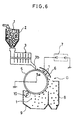
- This plastic sorting device comprises a frictional charging device 3 that is disposed below a hopper 2 adapted to have a plurality of kinds of plastic pieces 1 put therein and that is used to charge the plastic pieces 1 to give the latter a polarity and an amount of electric charge according to kind, and an electrostatic separator G disposed below said frictional charging device 3 and used to separate the charged plastic pieces 1 according to polarity and amount of electric charge.
- the electrostatic separator G comprises a metal drum electrode 5 disposed below the chute 3b of the frictional charging device 3, a high voltage electrode 6 disposed obliquely above the metal drum electrode 5, and a brush 10 for scraping the plastic pieces 1 sticking to the peripheral surface of the metal drum electrode 5.
- said metal drum electrode 5 is constructed for rotation around a horizontal axis 5a in a predetermined direction and is grounded.
- Connected to the high voltage electrode 6 is, for example, the cathode of a high voltage power source device 7, the anode thereof being grounded? This connection provides a sorting electrostatic field formed between the high voltage electrode 6 and the metal drum electrode 5.
- First and second separating vessels 8 and 9 for collecting according to kind the plastic pieces 1 that have passed through this sorting electrostatic field are fixedly disposed below the metal drum electrode 5.
- plastic sorting device when the plastic pieces 1 are put in the hopper 2, they are fed from the hopper 2 into the frictional charging device 3, where they are stirred and each frictionally charged to have a predetermined polarity and an amount of electric charge according to kind-based electrification rank. Thereafter, they fall down to the electrostatic separator G, pass through the sorting electrostatic field, and are collected in the separate vessels 8 and 9 as they are classified according to polarity and amount of electric charge.
- the plastic pieces 1 are each frictionally charged in the frictional charging device 3 to have a polarity and an amount of electric charge, with an electrification rank corresponding to the plastic pieces 1 established, and are separated by the electrostatic separator G and collected in the vessels 8 and 9 according to kind.
- the crushed plastic pieces 1 put in the hopper 2 differ in size (weight), so that when the plastic pieces 1 charged in the frictional charging device 3 pass through the sorting electrostatic field, their collected positions may vary according to the size of the plastic pieces 1 even if they assume the same position in the electrification rank, making it impossible to attain correct electrostatic separation according to kind.
- the present invention has for its object the provision of a plastic sorting device capable of solving said problem.
- the means for solving the problem according to the invention is to provide an arrangement comprising a frictional charging device for stirring and frictionally charging different kinds of crushed plastic pieces, a pair of electrostatic separating sections disposed below said frictional charging device for electrostatic separation of each plastic piece according to its polarity and amount of electric charge, each of said electrostatic separating sections having a drum electrode rotatable around a predetermined horizontal shaft, and an opposed electrode disposed adjacent said drum electrode through a separating space serving as a sorting electrostatic field, characterized by further comprising: a collecting section that is common to the electrostatic separating sections and that is disposed below the separating space between said drum electrodes for separately collecting plastic pieces that have passed through said separating space and thereby been separated, said collecting section having a plurality of collecting chambers for collecting plastic pieces according to kind; and a classifying section that, in frictionally charging said different kinds of crushed plastic pieces by the frictional charging device, classifies the plastic pieces according to size and load them into the frictional charging device.
- plastic pieces are classified according to size in the classifying section and then loaded into the frictional charging device, where they are stirred, and each plastic piece is electrostatically separated according to its polarity and amount of electric charge in the pair of electrostatic separating sections disposed below said frictional charging device.
- electrostatic separating sections the drum electrode rotatable around a predetermined horizontal shaft is rotated, the opposed electrode is disposed adjacent said drum electrode through a separating space serving as a sorting electrostatic field and has a voltage imposed thereon, and the plastic pieces are passed through the separating space and are separately collected in the common collecting section.
- the collecting section has partition walls for partitioning said plurality of collecting chambers, said partition walls being constructed to be adjustable for horizontal movement toward and away from the drum electrode, and a moving means is provided for horizontally moving the partition walls to the fall positions corresponding to the size of each plastic piece.
- the moving means is used for adjustment so as to horizontally move the partition walls toward and away from the drum electrode, so that electrostatic separation of the plastic pieces is correctly effected.
- the collecting section has partition walls for partitioning said plurality of collecting chambers, said partition walls being constructed to be swingable around support shafts parallel to the horizontal shaft of the drum electrode, and a swing means is provided for swinging the partition walls around the support shafts to the fall positions corresponding to the size of each plastic piece.
- the swing means is used to swing the partition walls around the support shafts parallel to the horizontal shaft of the drum electrode, so that electrostatic separation of the plastic pieces is correctly effected.
- the plastic sorting device 15 is used to separately collect different kinds of resin type plastic pieces (crushed waste to be sorted) 16; for example, as the plastic pieces 16, PE (polyethylene) and PP (polypropylene) are separately collected.
- PE polyethylene
- PP polypropylene
- the PE and PP to be used are crushed in advance on a 10-mm basis.
- the plastic sorting device 15 in the first embodiment of the invention comprises a screen member (classifying section) 40 with a vibrator 40a for classifying the plastic pieces 16 according to size, a pair of frictional charging devices 17A and 17B disposed below and on opposite sides of said screen member 40, a pair of electrostatic separators 41A and 41B disposed below said frictional charging devices 17A and 17B, and a common collecting section 26 disposed below the electrostatic separators 41A and 41B for collecting the plastic pieces 16 according to kind.
- the screen member 40 as shown in Fig. 1, comprises a flat classifying vessel 42, and a screen 44 disposed within said classifying vessel 42 such that it is downwardly inclined toward a first unloading port 43 to be later described, the meshes of said screen 44 being 10 mm.
- a loading port 45 for loading a mixture of different kinds and sizes of plastic pieces 16.
- the classifying vessel 42 is formed on its right-hand side with said first unloading port 43 for unloading the plastic pieces 16 that have been classified by the screen member 40 according to diameter, and on the lower left-hand side with a second unloading port 46 disposed on the lower left-hand side of the classifying vessel 42, said first unloading port 43 being used for unloading the plastic pieces 16 having sizes larger than 10 mm, said second unloading port 46 being used for unloading the plastic pieces 16 having sizes of 10 mm and less.
- the bottom plate 42a of the classifying vessel 42 is inclined opposite to the screen 44, that is, inclined toward the second unloading port 46.
- the frictional charging devices 17A and 17B are formed with openable/closable unloading ports 18a and 18b, the latter being provided with horizontally movable shutters 18c and 18d for opening and closing said unloading ports.
- Said electrostatic separators 41A and 41B are provided with unloading chutes 19A and 19B connected to the frictional charging devices 17A and 17B for frictionally charging PE and PP in the state of being loaded with PVC (polyvinyl chloride) to be later described mixed therein, a pair of metal drum electrodes 21A and 21B disposed close to the undersides of said unloading chutes 19A and 19B for rotation around predetermined horizontal shafts 20a and 20b and grounded, high voltage electrodes (opposed electrodes) 23A and 23B disposed obliquely upwardly of and opposed to the said metal drum electrodes 21A and 21B with separating spaces 22A and 22B disposed therebetween to serve as classifying electrostatic fields, a pair of high voltage power source devices 24A and 24B connected at their cathodes to said high voltage electrodes 23A and 23B and grounded at their positive electrodes, serving to impose high voltage on the separating spaces 22A and 22B, and brushes 25A and 25B disposed below the peripheral surfaces of the metal
- the collecting section 26 disposed below said separating spaces 22A and 22B comprises a plurality (in this case, 5) of collecting chambers 47, 48, 49, 50, and 51, four partition walls 52, 53, 54, and 55 for partitioning said collecting chambers 47, 48, 49, 50, and 51, and an outer peripheral wall 32, said partition walls 52, 53, 54, and 55 being constructed to be adjustable for horizontal movement toward and away from said metal drum electrodes 21A and 21B.
- a moving means 33 is installed for horizontally moving said partition walls 52, 53, 54, and 55 to positions to which the plastic pieces 16 separately drop according to polarity and amount of electric charge.
- the moving means 33 comprises a pair of guides 35 in which partition walls 52, 53, 54, and 55 are horizontally disposed for movement toward and away from said metal drum electrodes 21A 21B and which are individually attached to each partition wall 52, 53, 54, and 55 through a fitting member 34, a ball screw 37 threadedly fitted in a threaded member 36 attached to the fitting member 34 of the guide 35, and an unillustrated motor for rotating the ball screw 37.
- said collecting section 26 has a pair of reusing devices 39A and 39B attached thereto for returning PVC of said plastic pieces 16 to the frictional charging devices 17A and 17B through return tubes 38A and 38B.
- an image processor for observing the electrostatic separation of the plastic pieces 16 is installed in a predetermined location.
- the plastic pieces 16 to be sorted are frictionally charged by the frictional charging devices 17A and 17B, as a rule they are charged either plus or minus according to the electrification rank.
- the plastic pieces 16 to be sorted have closely adjacent positions in the electrification rank and include no material that has an intermediate position, such material is added as a friction material to the plastic pieces 16.
- said PVC is added as a friction material for sorting PE and PP.
- PE, PP, and PVC are stirred in the frictional charging devices 17A and 17B and thereby charged, the resulting electrification rank is (+) PE ⁇ PP ⁇ PVC (-).
- the plastic pieces 16 are crushed into a substantially spherical form on a 10-mm basis. And the plastic pieces 16 (a mixture of PE, PP, and PVC)are loaded through the loading port 45 of the screen member 49. Thereupon, the disposition of the screen 44, which is downwardly inclined toward the first unloading port 43, coupled with the vibrating action produced by the vibrator 40a, moves the plastic pieces 16 toward the first unloading port 43. At this time, the plastic pieces 16 that are more than 10 mm long remain on the screen 44 and are unloaded trough the first unloading port 43 and loaded into the frictional charging device 17A.
- the plastic pieces 16 that are more than 10 mm long remain on the screen 44 and are unloaded trough the first unloading port 43 and loaded into the frictional charging device 17A.
- the bottom plate 42a which is inclined to the side opposite to the screen 44, causes them to be unloaded through the second unloading port 46 of the classifying vessel 42 and loaded into the frictional charging device 17B.
- the plastic pieces 16 are frictionally charged individually on a 10-mm basis by the frictional charging devices 17A and 17B.
- the plastic pieces 16 frictionally charged by the frictional charging devices 17A and 17B fall through the unloading ports 18c and 18d, with the shutters 18a and 18b opened, and through the unloading chutes 19A and 19B onto the metal drum electrodes 21A and 21B. Thereupon, with the rotation of the metal drum electrodes 21A and 21B, the three kinds of plastic pieces 16 pass through the separating spaces 22A and 22B to fall into the collecting section 26.
- the PE which is charged (+)
- the PVC which is charged (-)
- the PP having an intermediate position in the electrification rank
- the plastic pieces 16 are separated according to diameter (weight); therefore, when the same voltage is imposed on the high voltage electrodes 23A and 23B, for example, there is a possibility that the fall positions of the plastic pieces 16 are deviated. In this case, there are possibilities of incorrect collection, such as the PE of small diameter, which should be collected in the collecting chamber 49, reaching the collecting chamber 50. Accordingly, the electrostatic separation of the plastic pieces 16 is observed by the image processor.
- the motor is driven to rotate the ball screw 37 according to the polarity and amount of electric charge imparted to the plastic pieces 16, so as to move at least one of the partition walls 52, 53, 54 and 55 toward and away from the metal drum electrode 21A or 21B, thereby adjusting the positions of the collecting chambers 47 - 51 to ensure that the PVC, PP, and PE are respectively collected in the collecting chambers 47 - 51 according to kind.
- Fig. 4 shows the results of electrostatic separation of the plastic pieces 16 with 30 kv imposed on the high voltage power source devices 24A and 24B, it being seen that the recovery rate and purity of PVC, PP, and PE were 80% or more. With the case of PE taken as an example, said recovery rate and purity are defined as follow.
- Recovery rate collected PE weight in collecting chamber 49 / total loaded PE weight
- Purity collected PE weight in collecting chamber 49 / collected plastic weight in collecting chamber 49
- the PVC used as a friction material has its electric charge removed and is cleaned by the reusing devices 39A and 39B and then fed back to the frictional charging devices 17A and 17B for reuse.
- the first embodiment of the invention comprises a collecting section 26 disposed below separating spaces 22A and 22B, said collecting section having partition walls 52, 53, 54, and 55 adjustable for horizontal movement toward and away from metal drum electrodes 21A and 21B, a moving means 33 for horizontally moving said partition walls 52, 53, 54, and 55 according to the fall positions associated with the polarity and amount of electric charge of each plastic piece 16, said moving means 33 comprising a pair of guides 35 in which the partition walls 52, 53, 54, and 55 are horizontally disposed for movement toward and away from said metal drum electrodes 21A and 21B and which are individually attached to each partition wall 52, 53, 54, and 55 through a fitting member 34, a ball screw 37 threadedly fitted in a threaded member 36 attached to the fitting member 34 of the guide 35, and an unillustrated motor for rotating the ball screw 37.
- the motor is driven to rotate the ball screw 37 to move the partition walls 52, 53, 54, and 55 according to the fall positions associated with the polarity and amount of electric charge of each plastic piece 16, the partition walls 52, 53, 54, and 55 being moved toward and away from the metal drum electrodes 21A and 21B; thus accurate separation can be effected without changing the voltage from the high voltage power source devices 24A and 24B and even if the plastic pieces 16 differ in weight because the plastic pieces 16 are separated in advance according to weight in that they are separated according to diameter by the screen member 40 and hence even if the plastic pieces 16 differ in diameter.
- FIG. 5 shows one electrostatic separator 41B alone.
- a plastic sorting device 15 according to the second embodiment of the invention is provided with a swing means 61 for swinging the partition walls 52, 53, 54, and 55 around said support shafts 60a - 60d according to the fall positions associated with the polarity and amount of electric charge of each plastic pieces 16, so as to move the partition walls 52, 53, 54, and 55 according to the fall positions associated with the polarity and amount of electric charge of each plastic pieces 16.
- the partition walls 52, 53, 54, and 55 are so constructed as to be swingable around the support shafts 60a - 60d parallel to the horizontal shafts 20a and 20b of said drum electrodes 21A and 21B according to the fall positions associated with the polarity and amount of electric charge of each plastic pieces 16, and the swing means 61, as shown in Fig. 5, comprises swing motors 63 attached to the support shafts 60a - 60d, and a controller 64 for driving these swing motors 63.
- the rest of the arrangement is the same as in the first embodiment described above and a description thereof is omitted.
- the motors 63 are driven to swing the support shafts 60a - 60d to move the partition walls 52, 53, 54, and 55 according to the fall positions associated with the polarity and amount of electric charge of each plastic pieces 16, moving the partition walls 52, 53, 54, and 55 toward and away from the metal drum electrodes 21A and 21B, whereby without changing the voltage from the high voltage power source devices 24A and 24B, the plastic pieces 16 can be correctly separated.
- the other operation/working-effects are the same as in the first embodiment described above, and a description thereof is omitted.
- PVC which takes (-) in the electrification rank
- the invention is not limited to the use of PVC, and PS (polystyrene) and PMMA (polymethyl methacrylate), which are on the (+) side, may be used, in which case PP is attracted to the metal drum electrodes 21A and 21B and collected in the collecting chambers 48 and 50, PE is collected in the collecting chamber 49, and PS or PMMA is collected in the collecting chambers 47 and 51.
- the invention provides an arrangement wherein disposed below frictional charging devices for stirring different kinds of crushed plastic pieces for frictional charging, is a pair of electrostatic separating sections for electrostatic separation of each plastic pieces according to the polarity and amount of electric charge thereof, each electrostatic separating section comprising a drum electrode rotatable around a predetermined horizontal shaft and an opposed electrode disposed adjacent the drum electrode through a separating space serving as a sorting electrostatic field, with a collecting section common to the electrostatic separating sections, disposed below the separating space between the drum electrodes for separately collecting the plastic pieces passing through said separating space and separated, said collecting section having a plurality of collecting chambers for collecting the plastic pieces according to kind, a classifying section being provided that, when plastic pieces are to be frictionally charged in the frictional charging devices, classifies the plastic pieces according to size and loading them into the frictional charging devices; thus accurate separation can be effected even if the plastic pieces differ in weight because the plastic pieces are separated in advance according to weight in that they are separated according to
- the collecting section comprises partition walls for partitioning a plurality of collecting chambers, said partition walls being constructed to be adjustable for horizontal movement toward and away from the drum electrodes, a moving means for horizontally moving the partition walls to the fall positions corresponding to the size of each plastic piece, or a swing means for swinging the partition walls around the support shafts to the fall positions corresponding to the size of each plastic pieces; therefore, plastic pieces can be correctly classified by moving or swinging the partition walls to the fall positions corresponding to the size of each plastic pieces by the moving means.
Landscapes
- Engineering & Computer Science (AREA)
- Environmental & Geological Engineering (AREA)
- Mechanical Engineering (AREA)
- Electrostatic Separation (AREA)
- Separation, Recovery Or Treatment Of Waste Materials Containing Plastics (AREA)
Abstract
Description
Claims (3)
- A plastic sorting device comprising a frictional charging device (17) for stirring and frictionally charging different kinds of crushed plastic pieces (16), a pair of electrostatic separating sections (41) disposed below said frictional charging device for electrostatic separation of each plastic piece according to its polarity and amount of electric charge, each of said electrostatic separating sections (41) having a drum electrode (21) rotatable around a predetermined horizontal shaft (20), and an opposed electrode (23) disposed adjacent said drum electrode (21) through a separating space (22) serving as a sorting electrostatic field, characterized by further comprising:a collecting section (26) that is common to the electrostatic separating sections and that is disposed below the separating space 22 between said drum electrodes for separately collecting plastic pieces that have passed through said separating space and thereby separated, said collecting section (26) having a plurality of collecting chambers (47 - 51) for collecting plastic pieces according to kind; anda classifying section (40) that, in frictionally charging said different kinds of crushed plastic pieces (16) by the frictional charging device (17), classifies the plastic pieces (16) according to size and load them into the frictional charging device (17).
- A plastic sorting device as set forth in Claim 1, characterized in that the collecting section (26) has partition walls (52 - 55) for partitioning said plurality of collecting chambers (47 - 51), said partition walls being constructed to be adjustable for horizontal movement toward and away from the drum electrode (21), and a moving means (33) is provided for horizontally moving the partition walls to fall positions corresponding to the size of each plastic piece.
- A plastic sorting device as set forth in Claim 1, characterized in that the collecting section (26) has partition walls (52 - 55) for partitioning said plurality of collecting chambers (47 - 51), said partition walls being constructed to be swingable around support shafts (60) parallel to the horizontal shaft of the drum electrode (21), and a swing means (61) is provided for swinging the partition walls around the support shafts to the fall positions corresponding to the size of each plastic piece.
Applications Claiming Priority (3)
| Application Number | Priority Date | Filing Date | Title |
|---|---|---|---|
| JP16029599A JP2000342997A (en) | 1999-06-08 | 1999-06-08 | Plastic sorting equipment |
| JP16029599 | 1999-06-08 | ||
| PCT/JP2000/001727 WO2000074855A1 (en) | 1999-06-08 | 2000-03-21 | Plastic chip separator |
Publications (3)
| Publication Number | Publication Date |
|---|---|
| EP1103306A1 true EP1103306A1 (en) | 2001-05-30 |
| EP1103306A4 EP1103306A4 (en) | 2004-03-31 |
| EP1103306B1 EP1103306B1 (en) | 2005-11-30 |
Family
ID=15711893
Family Applications (1)
| Application Number | Title | Priority Date | Filing Date |
|---|---|---|---|
| EP20000909781 Expired - Lifetime EP1103306B1 (en) | 1999-06-08 | 2000-03-21 | Plastic chip separator |
Country Status (8)
| Country | Link |
|---|---|
| US (1) | US6467628B1 (en) |
| EP (1) | EP1103306B1 (en) |
| JP (1) | JP2000342997A (en) |
| KR (1) | KR20010072336A (en) |
| CN (1) | CN1313792A (en) |
| DE (1) | DE60024398T2 (en) |
| TW (1) | TW458809B (en) |
| WO (1) | WO2000074855A1 (en) |
Cited By (2)
| Publication number | Priority date | Publication date | Assignee | Title |
|---|---|---|---|---|
| WO2010104409A1 (en) * | 2009-03-10 | 2010-09-16 | Afonso Lazaro Manuel Nunes Afonso | Electrostatic process and device for the separation of particles with equal electrical conductivity, applied to the purification coffee beans |
| CN112356347A (en) * | 2020-12-01 | 2021-02-12 | 张大柱 | A smash agitating unit for reclaimed plastic |
Families Citing this family (14)
| Publication number | Priority date | Publication date | Assignee | Title |
|---|---|---|---|---|
| US6072140A (en) * | 1998-02-10 | 2000-06-06 | Miller; Charles O. | Method and apparatus for electrically charging and separating particles |
| AUPQ902200A0 (en) * | 2000-07-27 | 2000-08-17 | Orekinetics Pty Ltd | Method and apparatus for the electrostatic separation of particulate materials |
| CN1315577C (en) * | 2000-09-04 | 2007-05-16 | 日立造船株式会社 | Apparatus for separating plastic chips |
| AU2003281513A1 (en) | 2002-07-22 | 2004-02-09 | Mba Polymers, Inc. | Mediating electrostatic separations |
| US6920982B2 (en) * | 2002-08-06 | 2005-07-26 | Eriez Magnetics | Plastic material having enhanced magnetic susceptibility, method of making and method of separating |
| JP2007111600A (en) * | 2005-10-19 | 2007-05-10 | Mitsubishi Electric Corp | Electrification sorting apparatus |
| US7383956B2 (en) * | 2005-11-25 | 2008-06-10 | Freeman Jimmy L | Woodwaste recycling apparatus and method |
| US7973258B2 (en) * | 2008-02-01 | 2011-07-05 | Eriez Manufacturing Co. | High-tension electrostatic separator lifting electrode |
| US20100247973A1 (en) * | 2009-03-27 | 2010-09-30 | Magnum Magnetics Corporation | Reduced-environmental-impact magnetic sheet systems |
| JP5578826B2 (en) * | 2009-10-02 | 2014-08-27 | 協和産業株式会社 | Waste plastic sorting and separation method and sorting and separation equipment |
| WO2014028012A2 (en) * | 2012-08-16 | 2014-02-20 | Empire Technology Development Llc | Electrostatic system and method for sorting plastics |
| CN102962139A (en) * | 2012-11-14 | 2013-03-13 | 邵道德 | Mixed particle static sorting device and application thereof |
| CN111497135A (en) * | 2020-05-03 | 2020-08-07 | 段芳利 | Working method of classified collection device for plastic products with different labels in injection molding production |
| CN116511094B (en) * | 2023-05-17 | 2025-01-17 | 昆山瑞格恩智慧科技有限公司 | A printed product sorting device based on visual inspection |
Family Cites Families (10)
| Publication number | Priority date | Publication date | Assignee | Title |
|---|---|---|---|---|
| GB588003A (en) * | 1945-07-31 | 1947-05-12 | Cyril Charlton | Clips or brackets to hold conduit tubes and the like |
| US2559076A (en) * | 1945-10-11 | 1951-07-03 | Quaker Oats Co | Method of cleaning coal |
| US3493109A (en) * | 1967-08-04 | 1970-02-03 | Consiglio Nazionale Ricerche | Process and apparatus for electrostatically separating ores with charging of the particles by triboelectricity |
| JPS5732748A (en) * | 1980-08-05 | 1982-02-22 | Japan Steel Works Ltd:The | Electrostatic-seperation equipment |
| DE4217480C2 (en) * | 1992-05-22 | 1995-03-23 | Noell Abfall & Energietech | Method and device for sorting commercial waste |
| JP3103812B2 (en) * | 1994-06-10 | 2000-10-30 | センコー工業株式会社 | Friction electrification electrostatic sorter |
| DE19522147C2 (en) * | 1995-06-19 | 1997-05-07 | Hamos Elektronik Gmbh | Device for the electrostatic sorting of mixtures of particles of different plastics |
| JPH09299827A (en) * | 1996-05-20 | 1997-11-25 | Densen Sogo Gijutsu Center | Equipment for separating electric wire coating material waste |
| DE19648373C1 (en) * | 1996-11-22 | 1998-01-08 | Kali & Salz Ag | Electrostatic separator for sorting triboelectrically supercharged mixtures |
| JP3506591B2 (en) * | 1997-03-26 | 2004-03-15 | 日立造船株式会社 | Friction charging device |
-
1999
- 1999-06-08 JP JP16029599A patent/JP2000342997A/en active Pending
-
2000
- 2000-03-16 TW TW89104843A patent/TW458809B/en not_active IP Right Cessation
- 2000-03-21 WO PCT/JP2000/001727 patent/WO2000074855A1/en not_active Ceased
- 2000-03-21 US US09/744,050 patent/US6467628B1/en not_active Expired - Fee Related
- 2000-03-21 KR KR1020017001666A patent/KR20010072336A/en not_active Ceased
- 2000-03-21 DE DE2000624398 patent/DE60024398T2/en not_active Expired - Fee Related
- 2000-03-21 CN CN00801056A patent/CN1313792A/en active Pending
- 2000-03-21 EP EP20000909781 patent/EP1103306B1/en not_active Expired - Lifetime
Cited By (2)
| Publication number | Priority date | Publication date | Assignee | Title |
|---|---|---|---|---|
| WO2010104409A1 (en) * | 2009-03-10 | 2010-09-16 | Afonso Lazaro Manuel Nunes Afonso | Electrostatic process and device for the separation of particles with equal electrical conductivity, applied to the purification coffee beans |
| CN112356347A (en) * | 2020-12-01 | 2021-02-12 | 张大柱 | A smash agitating unit for reclaimed plastic |
Also Published As
| Publication number | Publication date |
|---|---|
| JP2000342997A (en) | 2000-12-12 |
| CN1313792A (en) | 2001-09-19 |
| DE60024398T2 (en) | 2006-08-10 |
| EP1103306B1 (en) | 2005-11-30 |
| WO2000074855A1 (en) | 2000-12-14 |
| US6467628B1 (en) | 2002-10-22 |
| EP1103306A4 (en) | 2004-03-31 |
| KR20010072336A (en) | 2001-07-31 |
| DE60024398D1 (en) | 2006-01-05 |
| TW458809B (en) | 2001-10-11 |
Similar Documents
| Publication | Publication Date | Title |
|---|---|---|
| EP1103306B1 (en) | Plastic chip separator | |
| US6903294B1 (en) | Apparatus for separating plastic chips | |
| US6426474B1 (en) | Method and apparatus for separating plastic | |
| WO2000027536A1 (en) | Selector | |
| EP1132140B1 (en) | Method of separating plastic | |
| WO2000027535A1 (en) | Triboelectrification device | |
| JP3239564B2 (en) | Electrostatic sorting device | |
| JP3929236B2 (en) | Plastic friction charging device and plastic sorting equipment using the same | |
| JPH07178351A (en) | Electrostatic sorting device for rubber and plastic waste | |
| JP3640571B2 (en) | Plastic sorting equipment | |
| JP2001129435A (en) | Plastic sorting equipment | |
| JP3929216B2 (en) | Plastic sorting equipment | |
| WO1993006934A1 (en) | Electrostatic separation of plastic materials | |
| JP3549405B2 (en) | Plastic sorting device and plastic sorting method | |
| JP3573633B2 (en) | Friction charging device | |
| JP3657152B2 (en) | Plastic sorting equipment | |
| JP4056177B2 (en) | Plastic sorting method | |
| JP2000061358A (en) | Plastic sorting method and plastic sorting device | |
| JP2001121035A (en) | Plastic sorting equipment | |
| JP2000246141A (en) | Friction charging device | |
| JP2001096195A (en) | Plastic sorting equipment | |
| KR102602829B1 (en) | Fine particle sorting device | |
| JP2000325832A (en) | Plastic sorting equipment | |
| JP2001321694A (en) | Plastic sorting equipment | |
| JP2000061357A (en) | Plastic sorting method and plastic sorting device |
Legal Events
| Date | Code | Title | Description |
|---|---|---|---|
| PUAI | Public reference made under article 153(3) epc to a published international application that has entered the european phase |
Free format text: ORIGINAL CODE: 0009012 |
|
| 17P | Request for examination filed |
Effective date: 20010205 |
|
| AK | Designated contracting states |
Kind code of ref document: A1 Designated state(s): AT BE CH CY DE DK ES FI FR GB GR IE IT LI LU MC NL PT SE |
|
| A4 | Supplementary search report drawn up and despatched |
Effective date: 20040213 |
|
| RIC1 | Information provided on ipc code assigned before grant |
Ipc: 7B 03C 7/00 A Ipc: 7B 03C 7/06 B Ipc: 7B 29B 17/02 B |
|
| RBV | Designated contracting states (corrected) |
Designated state(s): DE FR |
|
| 17Q | First examination report despatched |
Effective date: 20040615 |
|
| GRAP | Despatch of communication of intention to grant a patent |
Free format text: ORIGINAL CODE: EPIDOSNIGR1 |
|
| GRAS | Grant fee paid |
Free format text: ORIGINAL CODE: EPIDOSNIGR3 |
|
| GRAA | (expected) grant |
Free format text: ORIGINAL CODE: 0009210 |
|
| AK | Designated contracting states |
Kind code of ref document: B1 Designated state(s): DE FR |
|
| REF | Corresponds to: |
Ref document number: 60024398 Country of ref document: DE Date of ref document: 20060105 Kind code of ref document: P |
|
| PLBE | No opposition filed within time limit |
Free format text: ORIGINAL CODE: 0009261 |
|
| STAA | Information on the status of an ep patent application or granted ep patent |
Free format text: STATUS: NO OPPOSITION FILED WITHIN TIME LIMIT |
|
| 26N | No opposition filed |
Effective date: 20060831 |
|
| EN | Fr: translation not filed | ||
| PG25 | Lapsed in a contracting state [announced via postgrant information from national office to epo] |
Ref country code: FR Free format text: LAPSE BECAUSE OF FAILURE TO SUBMIT A TRANSLATION OF THE DESCRIPTION OR TO PAY THE FEE WITHIN THE PRESCRIBED TIME-LIMIT Effective date: 20070119 |
|
| PGFP | Annual fee paid to national office [announced via postgrant information from national office to epo] |
Ref country code: DE Payment date: 20080310 Year of fee payment: 9 |
|
| PG25 | Lapsed in a contracting state [announced via postgrant information from national office to epo] |
Ref country code: FR Free format text: LAPSE BECAUSE OF FAILURE TO SUBMIT A TRANSLATION OF THE DESCRIPTION OR TO PAY THE FEE WITHIN THE PRESCRIBED TIME-LIMIT Effective date: 20060331 |
|
| PG25 | Lapsed in a contracting state [announced via postgrant information from national office to epo] |
Ref country code: FR Free format text: LAPSE BECAUSE OF FAILURE TO SUBMIT A TRANSLATION OF THE DESCRIPTION OR TO PAY THE FEE WITHIN THE PRESCRIBED TIME-LIMIT Effective date: 20051130 |
|
| PG25 | Lapsed in a contracting state [announced via postgrant information from national office to epo] |
Ref country code: DE Free format text: LAPSE BECAUSE OF NON-PAYMENT OF DUE FEES Effective date: 20091001 |