EP1103287B1 - Vorrichtung zum Aufrechterhalten eines positiven Ausatmungsdruckes - Google Patents
Vorrichtung zum Aufrechterhalten eines positiven Ausatmungsdruckes Download PDFInfo
- Publication number
- EP1103287B1 EP1103287B1 EP00307582A EP00307582A EP1103287B1 EP 1103287 B1 EP1103287 B1 EP 1103287B1 EP 00307582 A EP00307582 A EP 00307582A EP 00307582 A EP00307582 A EP 00307582A EP 1103287 B1 EP1103287 B1 EP 1103287B1
- Authority
- EP
- European Patent Office
- Prior art keywords
- expiratory
- air
- pressure
- expiratory air
- discharge orifice
- Prior art date
- Legal status (The legal status is an assumption and is not a legal conclusion. Google has not performed a legal analysis and makes no representation as to the accuracy of the status listed.)
- Expired - Lifetime
Links
Images


Classifications
-
- A—HUMAN NECESSITIES
- A63—SPORTS; GAMES; AMUSEMENTS
- A63B—APPARATUS FOR PHYSICAL TRAINING, GYMNASTICS, SWIMMING, CLIMBING, OR FENCING; BALL GAMES; TRAINING EQUIPMENT
- A63B23/00—Exercising apparatus specially adapted for particular parts of the body
- A63B23/18—Exercising apparatus specially adapted for particular parts of the body for improving respiratory function
-
- A—HUMAN NECESSITIES
- A61—MEDICAL OR VETERINARY SCIENCE; HYGIENE
- A61M—DEVICES FOR INTRODUCING MEDIA INTO, OR ONTO, THE BODY; DEVICES FOR TRANSDUCING BODY MEDIA OR FOR TAKING MEDIA FROM THE BODY; DEVICES FOR PRODUCING OR ENDING SLEEP OR STUPOR
- A61M16/00—Devices for influencing the respiratory system of patients by gas treatment, e.g. mouth-to-mouth respiration; Tracheal tubes
- A61M16/0003—Accessories therefor, e.g. sensors, vibrators, negative pressure
- A61M16/0006—Accessories therefor, e.g. sensors, vibrators, negative pressure with means for creating vibrations in patients' airways
-
- A—HUMAN NECESSITIES
- A61—MEDICAL OR VETERINARY SCIENCE; HYGIENE
- A61M—DEVICES FOR INTRODUCING MEDIA INTO, OR ONTO, THE BODY; DEVICES FOR TRANSDUCING BODY MEDIA OR FOR TAKING MEDIA FROM THE BODY; DEVICES FOR PRODUCING OR ENDING SLEEP OR STUPOR
- A61M16/00—Devices for influencing the respiratory system of patients by gas treatment, e.g. mouth-to-mouth respiration; Tracheal tubes
- A61M16/08—Bellows; Connecting tubes ; Water traps; Patient circuits
-
- A—HUMAN NECESSITIES
- A61—MEDICAL OR VETERINARY SCIENCE; HYGIENE
- A61M—DEVICES FOR INTRODUCING MEDIA INTO, OR ONTO, THE BODY; DEVICES FOR TRANSDUCING BODY MEDIA OR FOR TAKING MEDIA FROM THE BODY; DEVICES FOR PRODUCING OR ENDING SLEEP OR STUPOR
- A61M16/00—Devices for influencing the respiratory system of patients by gas treatment, e.g. mouth-to-mouth respiration; Tracheal tubes
- A61M16/20—Valves specially adapted to medical respiratory devices
- A61M16/201—Controlled valves
- A61M16/202—Controlled valves electrically actuated
- A61M16/203—Proportional
- A61M16/205—Proportional used for exhalation control
-
- A—HUMAN NECESSITIES
- A61—MEDICAL OR VETERINARY SCIENCE; HYGIENE
- A61M—DEVICES FOR INTRODUCING MEDIA INTO, OR ONTO, THE BODY; DEVICES FOR TRANSDUCING BODY MEDIA OR FOR TAKING MEDIA FROM THE BODY; DEVICES FOR PRODUCING OR ENDING SLEEP OR STUPOR
- A61M16/00—Devices for influencing the respiratory system of patients by gas treatment, e.g. mouth-to-mouth respiration; Tracheal tubes
- A61M16/20—Valves specially adapted to medical respiratory devices
- A61M16/208—Non-controlled one-way valves, e.g. exhalation, check, pop-off non-rebreathing valves
- A61M16/209—Relief valves
Definitions
- This invention relates in general to a hand-held, single patient use, positive expiratory pressure respiratory therapy device and, in particular, to a positive expiratory pressure respiratory therapy device utilizing a nonlinear orifice for adjusting and maintaining a desired pressure oscillation frequency in accordance with a predetermined pressure range of a patient's expiratory air.
- PEP positive expiratory pressure therapy
- a patient exhales against a resistance to generate expiratory pressure at a substantially constant rate of flow.
- Prescribed expiratory pressures are generally in the range of 10-20 cm H2O, although other pressure ranges and pressures can be used.
- PEP therapy has been documented by clinical research as equal to or superior to standard chest physiotherapy techniques which, while effective, are time consuming and not well tolerated by many patients who have difficulty breathing for extended periods of time in certain positions required for administration of standard chest physiotherapy. Accordingly, PEP therapy is believed to provide significant advantages to patients suffering from cystic fibrosis, and is felt to be an eventual replacement for chest physiotherapy for many patients.
- PEP therapy devices presently in use are very effective in the administration of the aforementioned type of PEP therapy. While an expensive pressure gauge can be connected to such a device to display the expiratory pressure being exerted by the patient, proper administration of the PEP therapy does not require the determination by the patient of an exact gauge pressure. Accordingly, PEP therapy can be properly administered as long as the patient can be made aware that the expiratory pressure is being maintained within a proper predetermined pressure range. Such a satisfactory PEP therapy device is disclosed in R.A. Niles et al U.S. Patent No.
- a single user respiratory therapy device includes a pressure range monitoring unit which provides a patient with a visual feed-back to monitor the correct use of a PEP device for enhancing the benefits of positive expiratory pressure therapy.
- a therapy device as defined in the preamble of claim 1 is disclosed in U.S. patent No. 5,451,190 .
- Russian patent No. 2 026 056 discloses a device for respiratory therapy comprising a regulator for providing a resistance to respiratory air flow, wherein said regulator comprises a magnetic valve.
- the present invention comprises an enhanced PEP therapy device which provides a variable frequency positive expiratory pressure by utilizing a nonlinear orifice for adjusting and maintaining a desired pressure oscillation frequency in accordance with a predetermined pressure range of a patient's expiratory air.
- another object of this invention is to utilise a variable frequency expiratory pressure in a positive expiratory pressure therapy device.
- a further object of this invention is obtain a variable frequency positive pressure in a positive expiratory pressure device by utilizing a nonlinear orifice to adjust and maintain a predetermined pressure oscillation frequency.
- the present invention provides a handheld, single patient use, positive expiratory pressure respiratory therapy device utilizing a nonlinear orifice for adjusting and maintaining a desired pressure oscillation frequency in accordance with a predetermined pressure range of a patient's expiratory air.
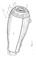
- FIGS. 1 and 2 there is illustrated in FIGS. 1 and 2 a hand-held, single patient user, positive expiratory pressure respiratory therapy device 1000 having a nonlinear orifice to provide a desired pressure oscillation frequency of the user's expiratory air.
- the device 1000 includes an expiratory air driven oscillatory rocker assembly 500 carried within a housing 100 formed in two portions, an upper housing portion 120 and a lower housing portion 150.
- a rotatable adjusting dial 600 is carried at an inspiratory air inlet end 201 of an air flow tube 200, and functions in a manner to be described hereinafter in detail to adjust the magnitude and the frequency of the user's exhalation pressure.
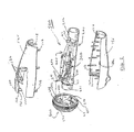
- the expiratory air driven oscillatory rocker assembly 500 is illustrated in the exploded view of FIG.3, and the components thereof are illustrated in more detail in FIGS. 4-9.
- FIG. 3 there is illustrated an air flow tube 200 having the inspiratory air inlet end 201 at one end and a patient input end 202 through which a patient inhales inspiratory air and discharges expiratory air.
- the inspiratory air inlet 201 and the patient input end 202 of the air flow tube 200 are sized as a 22mm male fitting.
- the air flow tube 200 can be used with a standard detachable mouthpiece or a mask of the type used with positive expiratory pressure respiratory therapy, or additional respiratory therapy equipment, such as a nebulizer or MDI spacer, having a standard female fitting to be received on such a fitting, also may be used with the invention.
- additional respiratory therapy equipment such as a nebulizer or MDI spacer, having a standard female fitting to be received on such a fitting, also may be used with the invention.
- the air flow tube 200 is open throughout its length, and includes at the inspiratory air inlet end 201 a one-way flapper valve 205.
- the flapper valve 205 allows a patient to draw inspiratory air into the air flow tube 200 through the air inlet end 201, but prevents expiratory air from being passed out of the air flow tube 200 through the air inlet end.
- the one way flapper valve 205 is positioned on a spider 206 which is inserted into the open air inlet end 201 against a shoulder 207 forming a space sufficient for the one way operation of the valve 205.
- the valve 205 Upon inhalation by a user, the valve 205 opens and allows air to pass into the air flow tube 200.
- the valve 205 is held closed against the spider 206 thereby preventing expiratory air from passing out through the inlet end 201.
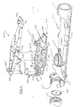
- the portion of the hollow air flow tube 200 between the inlet end 201 and the patient input end 202 includes a flat support platform 220 upon which the structures which create the patient induced oscillatory positive expiratory air pressure are carried.
- the support platform 220 includes a cylindrical collar or cowling 222 defining an air passage into the interior of the hollow air flow tube 200, and a pair of spaced abutments 225 into which portions of an adjustable orifice platform 310 of a magnet carriage 300 are secured.
- the collar 222 is downwardly tapered from a forward portion positioned toward the air inlet end 201 to a rear portion positioned toward the patient input end 202 to better accommodate the positioning of a complementary circular coupling portion 322 over the collar 222 to secure the adjustable orifice platform 310 to the air flow tube 200, and position the tapered conical interior surface 325 of the coupling 322 within the cowling 222.
- the tapered conical interior surface 325 closes the air passage into the air flow tube 200 except for a circular opening 326 which extends downwardly, as best illustrated in FIGS. 4 and 6, through the collar 222 into the hollow interior of the air flow tube 200.
- a pivotal magnet support 330 which depends from the adjustable orifice platform 310, in combination with a rocker assembly 400, forms a mechanism by which the discharge of a patient or user's expiratory air can be periodically interrupted to create a pulsating wave form, the frequency and magnitude of which can be adjusted between defined limits in accordance with the positive expiratory pressure treatment or therapy desired by a physician or clinician.
- the adjustable orifice platform 310 is positioned on the cowling 222 of the air flow tube 200 at a slight incline in the direction from the patient input end 202 towards the air inlet end 201 at a slope equal to the slope of the cowling 222 to which the circular coupling portion 322 is attached.
- a tang 335 carried on the longitudinal centerline of the platform 310 is positioned to engage the spaced abutments 225 formed on the support platform 220 to help secure and position the adjustable orifice platform 310 on the air flow tube 200.
- a pair of support bosses 336 extend downwardly from the platform 310 into contact with the support platform 220 of the air flow tube 200 to properly position the adjustable orifice platform 310 relative thereto.
- the contact surfaces where the tang 335 and each of the bosses 336 contact the support platform 220 are tapered to assist in this positioning.
- the adjustable orifice platform 310 also includes the pivotal magnet support 330 which is connected to the orifice platform 310 at an end 311 of the platform.
- the pivotal magnet support extends out from the end 311 encircling, but spaced from, the remainder of the platform 310 for pivotal movement relative thereto.
- the free end of the pivotal magnet support 330 terminates in a cam follower 340, which extends upwardly from the remainder of the magnet support 330, and has a tip 341 on the terminal portion thereof which extends horizontally in a plane substantially parallel to that of the encircling portion of the pivotal magnet support 330 for engaging a cam surface formed in the interior of the rotatable adjusting dial 600, as illustrated in Fig. 2.
- the relative position between the adjustable orifice platform 310 and the pivotal magnet support 330 can be set by rotating the rotatable adjusting dial 600.
- a magnet 350 is carried by the pivotal magnet support 330 at a position adjacent the base of the cam follower 340.
- the magnet 350 is held in position on the support 330 by a pair of engaging tabs 345 which are carried by the support and extend upwardly therefrom.
- Each of the engaging tabs 345 has a shoulder portion which engages a portion of the magnet 350 to secure the magnet 350 to the pivotal magnet support 330.
- a pair of guides 346 are also carried by the support 330 and assist in retaining the magnet 350 in a secured position on the support 330.
- the pivotal magnet support 330, the adjustable orifice platform 310 and the rocker assembly 400 form an expiratory air driven oscillatory rocker assembly 500 by which the expiratory air discharge of a patient or user can be periodically interrupted to create a pulsating wave form, the frequency and magnitude of which can be adjusted between defined limits in accordance with the positive expiratory pressure treatment or therapy desired by a physician or clinician.
- the adjustable orifice platform 310 includes a pair of spaced pivot supports 360 forming a pivot axis which lies in a plane above and extends transverse to the longitudinal axis of the pivotal magnet support 330 and the adjustable orifice platform 310, as best seen in PIGS. 4-6.
- pivot supports 360 receive the pivot pins 460 of the rocker assembly 400 upon which the rocker assembly 400 is pivotally moveable.
- One of a pair of locking guides 361 is positioned adjacent each of the pivot supports 360 to limit the axial movement of the rocker assembly 400 relative to the magnet carriage 300, and an overhanging shoulder portion 362 on each of the guides 361 prevents vertical movement of the rocker assembly pivot pins 460. In this manner the rocker assembly 400 remains pivotable on the pivot pins 460 regardless of the orientation of the device 1000 allowing the patient to receive therapy and use the device in any position.
- the rocker assembly 400 is balanced for pivotal movement about the pivot pins 460.
- a balancing pad 411 and balancing cylinder 412 are formed at one end of the rocker platform 410, to balance the weight of a flow cone 425 and a steel rod 450 carried at the opposite end of the rocker platform.
- the flow cone 425 is sized and positioned to be inserted into tapered conical interior 325 of the coupling 322 for closing the circular opening 326 into the air tube 200.
- the steel rod 450 is carried at the end opposed to the balancing pad 411 and balancing cylinder 412, in a pair of bifurcated mounting pads 445 which retain the ends of the steel rod 450 while allowing the remaining portion of the rod to be exposed. In this manner, the steel rod is exposed to the magnetic field of the magnet 350, and will be drawn thereto in accordance with the strength of the magnetic field and any force being exerted on the rocker platform 410 in opposition to the magnetic field.
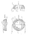
- the spacing therebetween is set by the operation of the rotatable adjusting dial 600, best illustrated in FIGS. 2 and 10-12.
- Rotation of the adjusting dial 600 acts on the tip 341 of the cam follower 340 through a pair of upper and lower parallel cam surfaces 641 and 642, respectively, formed on the interior of the adjusting dial.
- the cam surfaces 641 and 642 are formed as upper and lower parallel spaced walls into which the tip 341 of the cam follower 340 is inserted so that the vertical movement of the tip 341 will be determined by its position between the upper and lower cam surfaces. As illustrated diagrammatically in FIG.
- rotation of the adjusting dial 600 will move the magnet 350 from a position shown in solid lines wherein the magnet is at a maximum spacing from the steel rod 450, and thereby exerts a decreased magnet attracting force, to a position illustrated in phantom wherein the magnet is illustrated at a minimum spacing to the steel rod 450 whereby a maximum magnetic field attracting force will be exerted.
- the device 1000 While the device 1000 will function to provide an oscillatory positive expiratory pressure pulse without the use of the magnetic field between the magnet 350 and steel rod 450 because of the opening and closing of the orifice 326 by the movement of the cone 425 in response to the patient or user's expiratory air pressure, the use of the magnetic field permits the device 1000 to provide an adjustable range in the pressure of the patient's expiratory air discharge required to create the oscillatory positive expiratory pressure pulses.
- a plurality of indicia 625 are spaced about the periphery of the adjusting dial 600.
- the indicia 625 in combination with a base reference point 100 on the upper housing 120, are used to ensure that the correct setting is being maintained after the physician or clinician has established the desired level for treatment.
- a sounding board 610 is formed, such as by a thin chord of plastic material from which the adjusting dial is constructed, which extends across the lower internal portion of the adjusting dial 600 forming a chord portion joined to an inner wall 605 of the dial.
- An abutment 611 extends outwardly from the sounding board 610 which engages a plurality of teeth 211 formed circumferentially about the lower portion of the air flow tube 200 at the forward portion thereof adjacent to the inlet end 201 and the one-way flapper valve 205. In this manner, when the rotatable adjusting dial 200 is turned, an audible sound will be mechanically generated to signal that a change in position has occurred.
- the rotatable adjusting dial 600 is mounted on the inlet end 201 of the flow tube 200 and is rotatable about the inlet end and held in contact therewith by the abutment 611 and a pair of guides 650 which provides three point contact between the rotatable adjusting dial 600 and the inlet end 201 of the air flow tube.
- the adjusting dial 600 is formed with a circumferential groove 660 and circumferential flange 661 which engage complementary formed flanges and grooves, 160 and 161, respectively, on the upper and lower housing portions 120 and 150, respectively, to secure the dial 600 to the air flow tube 220 and housing of the PEP device 1000.
- a guide tab 665 is carried by the flange 661 to extend into the lower housing portion 150 to guide the rotational movement of dial 600.
- a boss 127 is carried at the forward portion of the upper housing 120 to prevent the expiratory air driven oscillatory rocker assembly 500 from being moved out of position or the cam follower tip 341 from moving out from engagement with the cam surfaces 641, 642.
- a plurality of bosses 126 are also formed on the housing portions 120 and 150 to strengthen the housing portions and to secure the internal components in their desired position.
- the air flow tube 200 with the expiratory air driven oscillatory rocker assembly 500 mounted thereon has the adjusting dial 600 positioned on the inlet end 201 with the cam follower tip 341 positioned between the two cam surfaces 641, 642, the assembly 500 is positioned into the lower housing 150, and the upper housing 120 installed thereover.
- a plurality of snap fittings 128 are formed on the upper housing 120 to engage receiving portions 158 formed on the lower housing 150 to secure the unit together.
- variable frequency positive expiratory pressure device 1000 During use of the variable frequency positive expiratory pressure device 1000, a patient inhales through the patient input end 202, drawing inspiratory air through the one-way valve 205 carried at the inlet end 201 of the air flow tube 220. The patient's expiratory air is then discharged into the patient input end 202, but must pass through the opening 326 of the adjustable orifice platform 310 because of the closure of the one-way valve 205 preventing air from flowing outwardly through the input end 201.
- the air pressure is applied through the opening 326 against the cone 425 of the rocker assembly 400 which forms a closure of the opening 326.
- the pressure of the patient expiratory air will raise the cone 425, causing the rocker assembly 400 to pivot about its pivot pins 460 against the force of the magnetic field between the magnet 350 carried on the pivotal magnet support 330 and the steel pin 450 carried on the rocker assembly.
- the tapered configuration of the tapered conical interior 325 of the coupling 322 increases the effective discharge area thereby decreasing the patient induced expiratory air pressure applied against the cone 425.
- the pulsating frequency and pressure will be low as illustrated in FIG. 14.
- the adjusting dial 600 is turned to reduce the spacing between the magnet 350 and steel rod 450, the magnetic field will be increased, thereby creating a higher frequency and pressure pulsation.
- Rotation of the adjustable dial 600 between the limits of the cam surfaces 641, 642 allows the physician or clinician to set a desired frequency and pressure for an individual patient or user, and the desired frequency and pressure can be replicated by referring to the indicia 625 on the adjusting dial.
Landscapes
- Health & Medical Sciences (AREA)
- Pulmonology (AREA)
- General Health & Medical Sciences (AREA)
- Life Sciences & Earth Sciences (AREA)
- Emergency Medicine (AREA)
- Biomedical Technology (AREA)
- Heart & Thoracic Surgery (AREA)
- Hematology (AREA)
- Engineering & Computer Science (AREA)
- Animal Behavior & Ethology (AREA)
- Anesthesiology (AREA)
- Public Health (AREA)
- Veterinary Medicine (AREA)
- Physical Education & Sports Medicine (AREA)
- Percussion Or Vibration Massage (AREA)
- Portable Nailing Machines And Staplers (AREA)
- Measurement Of The Respiration, Hearing Ability, Form, And Blood Characteristics Of Living Organisms (AREA)
Claims (8)
- Ausatmungsüberdruck-Therapievorrichtung (1000) zur Herbeiführung eines Oszillations-Ausatmungsluftdrucks durch einen Patienten, umfassend:eine Luftströmungsröhre (200) mit einer Einlassöffnung (201), durch die ein zu behandelnder Patient Einatmungsluft einatmet, und mit einer Patienten-Zufuhröffnung (202), durch die ein Patient einatmet, um Einatmungsluft in die Luftströmungsröhre zu saugen und durch die ein Patient ausatmet, um Ausatmungsluft aus der Luftströmungsröhre (200) auszustoßen;ein Einwegventil (205), das an der Luftströmungsröhren-Einlassöffnung (201) gehalten ist, damit durch diese hindurch Einatmungsluft gesaugt werden kann, wobei die Durchleitung von Ausatmungsluft durch diese hindurch jedoch gesperrt wird;und wobei die Luftströmungsröhre (200) zudem einen nicht-linearen Ausstoßauslass (326) umfasst, dessen Öffnung während der Durchleitung von Einatmungsluft durch die Einlassöffnung (201) geschlossen wird und als Reaktion auf den Ausstoss von Ausatmungsluft geöffnet wird,gekennzeichnet durch
ein Steuerungsmittel zur Erzeugung von Oszillations-Ausatmungsluftdruck durch Steuern des Öffnens und des Schließens des nicht-linearen Ausstoßauslasses (326) als Antwort auf den Druck der in die Patienten-Zufuhröffnung (202) ausgestoßenen Ausatmungsluft. - Ausatmungsüberdruck-Therapievorrichtung nach Anspruch 1, worin das Steuerungsmittel ein Auslassverschlussmittel umfasst, das normalerweise den nicht-linearen Ausstoßauslass (326) schließt, jedoch auch betätigbar ist, um den nicht-linearen Ausstoßauslass (326) als Antwort auf den in die Patienten-Zufuhröffnung (202) ausgestoßenen Ausatmungsluftdruck zu öffnen.
- Ausatmungsüberdruck-Therapievorrichtung nach Anspruch 2, worin das nichtlineare Ausstoßauslass-Verschlussmittel einen Konus (425) umfasst, der schwenkbar in den und aus dem nicht-linearen Ausstoßauslass (326) bewegbar ist, als Antwort auf den Druck der Ausatmungsluft, die in die Patienten-Zufuhröffnung ausgestoßen wird.
- Ausatmungsüberdruck-Therapievorrichtung nach Anspruch 3, worin das Steuerungsmittel ein magnetisches Kraftfeld umfasst, das den schwenkbar beweglichen Konus (425) in eine Position zum Verschließen des nicht-linearen Ausstoßauslasses (326) vorspannt.
- Ausatmungsüberdruck-Therapievorrichtung nach Anspruch 4, die weiters ein Mittel zum Einstellen der Größe des magnetischen Kraftfelds umfasst, das den schwenkbar beweglichen Konus in eine Position zum Verschließen des nicht-linearen Ausstoßauslasses (326) vorspannt.
- Verfahren zur Steuerung eines Oszillations-Ausatmungsluftimpulses in einer Ausatmungsüberdruck-Therapievorrichtung, Folgendes umfassend:Durchleiten eines Stroms von durch einen Patienten herbeigeführter Ausatmungsluft in eine Luftströmungsröhre (200) mit einem nicht-linearen Ausstoßauslass, durch welchen Ausatmungsluft ausgestoßen wird;Unterbrechen des Ausstoßes von Ausatmungsluft durch den nicht-linearen Ausstoßauslass (326) durch Verschließen des Auslasses bis der Ausatmungsluftdruck einen vorbestimmten Wert erreicht;Öffnen des Ausstoßauslasses (326), um das Ausstoßen von Ausatmungsluft durch diesen zu ermöglichen bis der Druck der ausgestoßenen Ausatmungsluft unter den vorbestimmten Wert fällt; undAnlegen einer Vorspannungskraft zum Schließen des Ausstoßauslasses (326), um den vorbestimmten Wert des Ausatmungsluftdrucks zu steuern.
- Verfahren zur Steuerung eines Oszillations-Ausatmungstuftimpulses in einer Ausatmungsüberdruck-Therapievorrichtung nach Anspruch 6, worin der Schritt des Anlegens einer Vorspannungskraft das Herbeiführen eines magnetischen Kraftfelds umfasst, um den vorbestimmten Wert des Ausatmungsluftdrucks zu steuern.
- Verfahren zur Steuerung eines Oszillations-Ausatmungsluftimpulses in einer Ausatmungsüberdruck-Therapievorrichtung nach Anspruch 7, worin der Schritt des Anlegens einer Vorspannungskraft zum Verschließen des Ausstoßauslasses (326) zur Steuerung des vorbestimmten Werts des Ausatmungsluftdrucks das Anlegen einer durch Venturi-Wirkung herbeigeführten Kraft zum Verschließen des Ausstoßauslasses umfasst.
Applications Claiming Priority (2)
| Application Number | Priority Date | Filing Date | Title |
|---|---|---|---|
| US449208 | 1995-05-24 | ||
| US09/449,208 US6581598B1 (en) | 1999-11-24 | 1999-11-24 | Positive expiratory pressure device |
Publications (3)
| Publication Number | Publication Date |
|---|---|
| EP1103287A2 EP1103287A2 (de) | 2001-05-30 |
| EP1103287A3 EP1103287A3 (de) | 2003-04-02 |
| EP1103287B1 true EP1103287B1 (de) | 2007-06-27 |
Family
ID=23783321
Family Applications (1)
| Application Number | Title | Priority Date | Filing Date |
|---|---|---|---|
| EP00307582A Expired - Lifetime EP1103287B1 (de) | 1999-11-24 | 2000-09-04 | Vorrichtung zum Aufrechterhalten eines positiven Ausatmungsdruckes |
Country Status (5)
| Country | Link |
|---|---|
| US (1) | US6581598B1 (de) |
| EP (1) | EP1103287B1 (de) |
| AT (1) | ATE365577T1 (de) |
| DE (1) | DE60035328T2 (de) |
| ES (1) | ES2288832T3 (de) |
Cited By (16)
| Publication number | Priority date | Publication date | Assignee | Title |
|---|---|---|---|---|
| US8327849B2 (en) | 2008-10-28 | 2012-12-11 | Trudell Medical International | Oscillating positive expiratory pressure device |
| US8485179B1 (en) | 2009-02-23 | 2013-07-16 | Trudell Medical International | Oscillating positive expiratory pressure device |
| US8539951B1 (en) | 2008-05-27 | 2013-09-24 | Trudell Medical International | Oscillating positive respiratory pressure device |
| USD731050S1 (en) | 2011-06-06 | 2015-06-02 | Trudell Medical International | Oscillating positive expiratory pressure device |
| US9149589B2 (en) | 2009-02-23 | 2015-10-06 | Trudell Medical International | Method and device for performing orientation dependent oscillating positive expiratory pressure therapy |
| US9517315B2 (en) | 2012-11-30 | 2016-12-13 | Trudell Medical International | Oscillating positive expiratory pressure device |
| USD778429S1 (en) | 2015-09-02 | 2017-02-07 | Trudell Medical International | Respiratory treatment device |
| USD780906S1 (en) | 2015-09-02 | 2017-03-07 | Trudell Medical International | Respiratory treatment device |
| US9849257B2 (en) | 2013-08-22 | 2017-12-26 | Trudell Medical International | Oscillating positive respiratory pressure device |
| US10272224B2 (en) | 2013-07-12 | 2019-04-30 | Trudell Medical International | Huff cough simulation device |
| US10857317B2 (en) | 2015-12-04 | 2020-12-08 | Trudell Medical International | Huff cough simulation device |
| US10953278B2 (en) | 2018-02-02 | 2021-03-23 | Trudell Medical International | Oscillating positive expiratory pressure device |
| US11116923B2 (en) | 2014-02-07 | 2021-09-14 | Trudell Medical International | Pressure indicator for an oscillating positive expiratory pressure device |
| US11260197B2 (en) | 2015-07-30 | 2022-03-01 | Trudell Medical International | Combined respiratory muscle training and oscillating positive expiratory pressure device |
| US11452838B2 (en) | 2011-04-28 | 2022-09-27 | Michael J. Rusher | Positive expiratory pressure devices with flutter valve |
| US11559723B2 (en) | 2017-05-03 | 2023-01-24 | Trudell Medical International | Combined oscillating positive expiratory pressure therapy and Huff Cough simulation device |
Families Citing this family (70)
| Publication number | Priority date | Publication date | Assignee | Title |
|---|---|---|---|---|
| US6776159B2 (en) * | 1999-11-24 | 2004-08-17 | Dhd Healthcare Corporation | Positive expiratory pressure device with bypass |
| US7059324B2 (en) | 1999-11-24 | 2006-06-13 | Smiths Medical Asd, Inc. | Positive expiratory pressure device with bypass |
| CA2919286A1 (en) * | 2000-04-11 | 2001-10-18 | Trudell Medical International | Respiratory apparatus |
| US6904908B2 (en) | 2002-05-21 | 2005-06-14 | Trudell Medical International | Visual indicator for an aerosol medication delivery apparatus and system |
| US6994087B1 (en) * | 2004-12-02 | 2006-02-07 | Smith John D | Esophageal intubation detection system |
| US10610228B2 (en) | 2004-12-08 | 2020-04-07 | Theravent, Inc. | Passive nasal peep devices |
| US8061357B2 (en) * | 2004-12-08 | 2011-11-22 | Ventus Medical, Inc. | Adhesive nasal respiratory devices |
| US9833354B2 (en) | 2004-12-08 | 2017-12-05 | Theravent, Inc. | Nasal respiratory devices |
| SG171607A1 (en) | 2004-12-08 | 2011-06-29 | Ventus Medical Inc | Respiratory devices and methods of use |
| US7909033B2 (en) | 2006-05-03 | 2011-03-22 | Comedica Incorporated | Breathing treatment apparatus |
| WO2007139890A2 (en) * | 2006-05-23 | 2007-12-06 | Ventus Medical, Inc. | Nasal respiratory devices |
| CA2658966A1 (en) | 2006-06-07 | 2007-12-21 | Ventus Medical, Inc. | Layered nasal devices |
| CN101489630B (zh) | 2006-06-07 | 2013-10-23 | 温吐斯医学公司 | 分层鼻装置 |
| GB2441584A (en) | 2006-09-05 | 2008-03-12 | South Bank Univ Entpr Ltd | Breathing device |
| GB2441583A (en) | 2006-09-05 | 2008-03-12 | South Bank Univ Entpr Ltd | Breathing device |
| US8051854B2 (en) * | 2006-09-15 | 2011-11-08 | Comedica Incorporated | Continuous high-frequency oscillation breathing treatment apparatus |
| US8225785B2 (en) | 2006-10-03 | 2012-07-24 | Smiths Medical Asd, Inc. | Vibratory PEP therapy system with medicated aerosol nebulizer |
| US7779841B2 (en) | 2006-11-13 | 2010-08-24 | Carefusion 2200, Inc. | Respiratory therapy device and method |
| WO2008061250A2 (en) * | 2006-11-16 | 2008-05-22 | Ventus Medical, Inc. | Adjustable nasal devices |
| GB0625303D0 (en) * | 2006-12-19 | 2007-01-24 | Jagotec Ag | Improvements in and relating to metered dose inhalers |
| US20080223361A1 (en) * | 2007-03-14 | 2008-09-18 | Peter Nieuwstad | Respiratory medicine delivery system |
| NZ580224A (en) * | 2007-04-02 | 2011-05-27 | Allegiance Corp | High frequency oscillation respiratory therapy device |
| GB0706561D0 (en) * | 2007-04-03 | 2007-05-09 | Smiths Group Plc | Pulmonary therapy device |
| US9050434B2 (en) | 2007-05-18 | 2015-06-09 | Comedica Incorporated | Lung therapy device |
| DE102007025809B3 (de) * | 2007-06-02 | 2008-10-16 | Dräger Medical AG & Co. KG | Kohlendioxidabsorber für ein Rückatemsystem |
| US8020700B2 (en) | 2007-12-05 | 2011-09-20 | Ventus Medical, Inc. | Packaging and dispensing nasal devices |
| US20090194109A1 (en) * | 2008-02-01 | 2009-08-06 | Rajiv Doshi | Cpap interface and backup devices |
| US20130157810A1 (en) * | 2008-02-15 | 2013-06-20 | College Of William And Mary | Nasal inspiratory resistance trainer |
| US8376752B2 (en) * | 2008-02-15 | 2013-02-19 | College Of William And Mary | Nasal inspiratory resistance trainer |
| US8251876B2 (en) | 2008-04-22 | 2012-08-28 | Hill-Rom Services, Inc. | Breathing exercise apparatus |
| US20110100360A1 (en) * | 2009-11-02 | 2011-05-05 | Joseph Dee Faram | Composite lung therapy device and method |
| US9151425B2 (en) * | 2009-11-02 | 2015-10-06 | Comedica Incorporated | Multiple conduit connector apparatus and method |
| NL2004434C2 (en) * | 2010-03-19 | 2011-09-20 | Rob Janssen | Oropharyngeal training tool and training method. |
| US8875711B2 (en) | 2010-05-27 | 2014-11-04 | Theravent, Inc. | Layered nasal respiratory devices |
| US10039691B2 (en) | 2010-09-21 | 2018-08-07 | Koninklijke Philips N.V. | Vibratory positive expiratory pressure device |
| EP2444114B1 (de) * | 2010-10-20 | 2016-09-28 | Hill-Rom Services Pte. Ltd. | Vorrichtung zur positiven Ausatmungsdrucktherapie |
| US9084859B2 (en) | 2011-03-14 | 2015-07-21 | Sleepnea Llc | Energy-harvesting respiratory method and device |
| US9180271B2 (en) | 2012-03-05 | 2015-11-10 | Hill-Rom Services Pte. Ltd. | Respiratory therapy device having standard and oscillatory PEP with nebulizer |
| US9795752B2 (en) | 2012-12-03 | 2017-10-24 | Mhs Care-Innovation, Llc | Combination respiratory therapy device, system, and method |
| US9233274B2 (en) | 2013-03-14 | 2016-01-12 | D R Burton Healthcare, Llc | Combination spirometer and PEP breathing exerciser |
| GB2512047B (en) * | 2013-03-15 | 2015-07-15 | Univ Sheffield Hallam | Positive Expiratory Pressure Device With Electronic Monitoring |
| EP2783728B1 (de) * | 2013-03-26 | 2016-12-14 | R. Cegla GmbH & Co. KG | Therapiegerät zur Behandlung von Atemwegserkrankungen |
| GB201310824D0 (en) | 2013-06-18 | 2013-07-31 | Smiths Medical Int Ltd | Respiratory therapy apparatus and methods |
| GB201310826D0 (en) | 2013-06-18 | 2013-07-31 | Smiths Medical Int Ltd | Respiratory therapy apparatus and methods |
| GB201316223D0 (en) * | 2013-09-12 | 2013-10-30 | Smiths Medical Int Ltd | Respiratory therapy apparatus and methods |
| GB201400188D0 (en) * | 2014-01-07 | 2014-02-26 | Smiths Medical Int Ltd | Respiratory therapy apparatus |
| GB201401566D0 (en) * | 2014-01-30 | 2014-03-19 | Smiths Medical Int Ltd | Respiratory therapy systems, sensors and methods |
| GB201404265D0 (en) | 2014-03-11 | 2014-04-23 | Smiths Medical Int Ltd | Respiratory analysis and treatment |
| GB201407571D0 (en) | 2014-04-30 | 2014-06-11 | Smiths Medical Int Ltd | Respiratory therapy devices |
| GB201412867D0 (en) * | 2014-07-19 | 2014-09-03 | Smiths Medical Int Ltd | Respiratory therapy devices |
| GB201420127D0 (en) | 2014-11-12 | 2014-12-24 | Smiths Medical Int Ltd | Respiratory therapy apparatus |
| GB201420518D0 (en) | 2014-11-19 | 2014-12-31 | Smiths Medical Int Ltd | Respiratory therapy apparatus |
| WO2016092247A1 (en) | 2014-12-11 | 2016-06-16 | Smiths Medical International Limited | Respiratory therapy apparatus |
| US10004872B1 (en) | 2015-03-06 | 2018-06-26 | D R Burton Healthcare, Llc | Positive expiratory pressure device having an oscillating valve |
| AU2016243801B2 (en) | 2015-04-02 | 2020-05-21 | Hill-Rom Services Pte. Ltd. | Manifold for respiratory device |
| WO2017178776A1 (en) | 2016-04-14 | 2017-10-19 | Smiths Medical International Limited | Respiratory therapy devices |
| WO2017187116A1 (en) | 2016-04-27 | 2017-11-02 | Smiths Medical International Limited | Respiratory therapy apparatus |
| GB201608128D0 (en) | 2016-05-07 | 2016-06-22 | Smiths Medical Int Ltd | Respiratory monitoring apparatus |
| MX2020013097A (es) | 2018-06-04 | 2021-02-17 | Trudell Medical Int | Dispositivo de terapia de presion de aire positiva, kit y metodos para el uso y ensamble del mismo. |
| GB201809559D0 (en) | 2018-06-09 | 2018-07-25 | Smiths Medical International Ltd | Respiratory therapy apparatus and methods |
| GB201810197D0 (en) | 2018-06-21 | 2018-08-08 | Smiths Medical International Ltd | Respiratory therapy devices and assemblies |
| GB201904825D0 (en) | 2019-04-05 | 2019-05-22 | Smiths Medical International Ltd | Respiratory therapy apparatus |
| US10780318B1 (en) | 2019-04-18 | 2020-09-22 | Firas Kasem Ghazzawi | Breathing device with exhale and inhale valve to create resistance |
| USD875237S1 (en) | 2019-04-18 | 2020-02-11 | Firas Kasem Ghazzawi | Resistance breathing device |
| US11813397B2 (en) * | 2019-06-11 | 2023-11-14 | Justin Rowley | Nebulizer with flutter valve |
| GB202010540D0 (en) | 2020-07-09 | 2020-08-26 | Smiths Medical International Ltd | Respiratory therapy device |
| TWI779663B (zh) * | 2021-06-15 | 2022-10-01 | 岩成科技事業股份有限公司 | 震盪式吐氣正壓裝置 |
| GB202109719D0 (en) | 2021-07-06 | 2021-08-18 | Smiths Medical International Ltd | Respiratory therapy devices |
| GB202110225D0 (en) | 2021-07-15 | 2021-09-01 | Smiths Medical International Ltd | Respiratory therapy devices |
| CN113648619A (zh) * | 2021-09-26 | 2021-11-16 | 重庆上品益生电子商务有限公司 | 呼吸训练器 |
Family Cites Families (27)
| Publication number | Priority date | Publication date | Assignee | Title |
|---|---|---|---|---|
| US2918917A (en) * | 1955-03-02 | 1959-12-29 | John H Emerson | Apparatus for vibrating portions of a patient's airway |
| US3710780A (en) * | 1971-08-05 | 1973-01-16 | R Milch | Respiratory device with variable expiratory pressure resistance |
| US4221381A (en) * | 1978-12-26 | 1980-09-09 | Albany International Corp. | Respiratory exerciser |
| US4327740A (en) * | 1979-11-19 | 1982-05-04 | Clyde Shuman | Incentive spirometer |
| US4601465A (en) * | 1984-03-22 | 1986-07-22 | Roy Jean Yves | Device for stimulating the human respiratory system |
| US4611591A (en) * | 1984-07-10 | 1986-09-16 | Sharp Kabushiki Kaisha | Expiration valve control for automatic respirator |
| US4651731A (en) * | 1984-09-17 | 1987-03-24 | Figgie International Inc. | Self-contained portable single patient ventilator/resuscitator |
| US4739987A (en) * | 1985-10-28 | 1988-04-26 | Nicholson Marguerite K | Respiratory exerciser |
| DK168888A (da) * | 1988-03-25 | 1989-09-26 | Ambu Int As | Apparat til respirationstraening |
| DE3822949A1 (de) * | 1988-07-07 | 1990-01-11 | Draegerwerk Ag | Pneumatisches steuerventil |
| EP0372148A1 (de) * | 1988-12-09 | 1990-06-13 | Erik Folke Norell | Vorrichtung zur Übung der Lunge |
| BE1004384A3 (nl) * | 1989-08-03 | 1992-11-10 | Labaere Emmanuel | Toestel voor het toepassen van in- en uitademingstechnieken. |
| US5027809A (en) * | 1990-05-17 | 1991-07-02 | Robinson Pat D | "Peeper" performance hand held nebuilizer attachment with adjustability of expiratory pressures and expiratory restriction |
| RU2026056C1 (ru) * | 1991-02-15 | 1995-01-09 | Николай Васильевич Зародин | Устройство для профилактики и лечения заболеваний дыхательной системы |
| RU2026057C1 (ru) * | 1991-02-15 | 1995-01-09 | Николай Васильевич Зародин | Устройство для профилактики и лечения заболеваний дыхательной системы |
| CH685475A5 (fr) * | 1992-04-10 | 1995-07-31 | Varioraw Percutive Sa | Appareil thérapeutique spécifique du domaine respiratoire. |
| US5439430A (en) * | 1993-05-10 | 1995-08-08 | Rubens; Louis C. | Respiratory exerciser |
| US5598839A (en) | 1994-04-20 | 1997-02-04 | Diemolding Corporation | Positive expiratory pressure device |
| US5540220A (en) * | 1994-12-08 | 1996-07-30 | Bear Medical Systems, Inc. | Pressure-limited, time-cycled pulmonary ventilation with volume-cycle override |
| US6083141A (en) * | 1995-02-10 | 2000-07-04 | Hougen; Everett D. | Portable respiratory exercise apparatus and method for using the same |
| US5658221A (en) * | 1995-02-10 | 1997-08-19 | Hougen; Everett D. | Portable personal breathing apparatus and method of using same |
| EP0808197A4 (de) * | 1995-02-10 | 2001-03-28 | Everett D Hougen | Tragbares, persönliches atmungsgerät |
| US5632298A (en) * | 1995-03-17 | 1997-05-27 | Artinian; Hagop | Resuscitation and inhalation device |
| US5899832A (en) * | 1996-06-14 | 1999-05-04 | Hougen; Everett D. | Compact lung exercising device |
| US5791339A (en) * | 1997-03-13 | 1998-08-11 | Nellcor Puritan Bennettt Incorprated | Spring piloted safety valve with jet venturi bias |
| US6058932A (en) * | 1997-04-21 | 2000-05-09 | Hughes; Arthur R. | Acoustic transceiver respiratory therapy apparatus |
| US6102038A (en) * | 1998-05-15 | 2000-08-15 | Pulmonetic Systems, Inc. | Exhalation valve for mechanical ventilator |
-
1999
- 1999-11-24 US US09/449,208 patent/US6581598B1/en not_active Expired - Lifetime
-
2000
- 2000-09-04 EP EP00307582A patent/EP1103287B1/de not_active Expired - Lifetime
- 2000-09-04 AT AT00307582T patent/ATE365577T1/de not_active IP Right Cessation
- 2000-09-04 DE DE60035328T patent/DE60035328T2/de not_active Expired - Lifetime
- 2000-09-04 ES ES00307582T patent/ES2288832T3/es not_active Expired - Lifetime
Cited By (42)
| Publication number | Priority date | Publication date | Assignee | Title |
|---|---|---|---|---|
| US8539951B1 (en) | 2008-05-27 | 2013-09-24 | Trudell Medical International | Oscillating positive respiratory pressure device |
| US10668235B2 (en) | 2008-05-27 | 2020-06-02 | Trudell Medical International | Oscillating positive respiratory pressure device |
| US9808588B1 (en) | 2008-05-27 | 2017-11-07 | Trudell Medical International | Oscillating positive respiratory pressure device |
| US9636473B2 (en) | 2008-05-27 | 2017-05-02 | Trudell Medical International | Oscillating positive respiratory pressure device |
| US11865254B2 (en) | 2008-10-28 | 2024-01-09 | Trudell Medical International | Oscillating positive expiratory pressure device |
| US8327849B2 (en) | 2008-10-28 | 2012-12-11 | Trudell Medical International | Oscillating positive expiratory pressure device |
| US8985111B2 (en) | 2008-10-28 | 2015-03-24 | Trudell Medical International | Oscillating positive expiratory pressure device |
| US10668238B2 (en) | 2008-10-28 | 2020-06-02 | Trudell Medical International | Oscillating positive expiratory pressure device |
| US9913955B2 (en) | 2008-10-28 | 2018-03-13 | Trudell Medical International | Oscillating positive expiratory pressure device |
| US9737677B2 (en) | 2008-10-28 | 2017-08-22 | Trudell Medical International | Oscillating positive expiratory pressure device |
| US10722668B2 (en) | 2009-02-23 | 2020-07-28 | Trudell Medical International | Oscillating positive expiratory pressure device |
| US11547819B2 (en) | 2009-02-23 | 2023-01-10 | Trudell Medical International | Device for performing orientation dependent aerosol therapy |
| US9149589B2 (en) | 2009-02-23 | 2015-10-06 | Trudell Medical International | Method and device for performing orientation dependent oscillating positive expiratory pressure therapy |
| US11529480B2 (en) | 2009-02-23 | 2022-12-20 | Trudell Medical International | Oscillating positive expiratory pressure device |
| US10729863B2 (en) | 2009-02-23 | 2020-08-04 | Trudell Medical International | Method and device for performing orientation dependent oscillating positive expiratory pressure therapy |
| US8485179B1 (en) | 2009-02-23 | 2013-07-16 | Trudell Medical International | Oscillating positive expiratory pressure device |
| US9220855B2 (en) | 2009-02-23 | 2015-12-29 | Trudell Medical International | Oscillating positive expiratory pressure device |
| US9950128B2 (en) | 2009-02-23 | 2018-04-24 | Trudell Medical International | Oscillating positive expiratory pressure device |
| US11452838B2 (en) | 2011-04-28 | 2022-09-27 | Michael J. Rusher | Positive expiratory pressure devices with flutter valve |
| US9981106B2 (en) | 2011-06-06 | 2018-05-29 | Trudell Medical International | Oscillating positive expiratory pressure device |
| US11040167B2 (en) | 2011-06-06 | 2021-06-22 | Trudell Medical International | Oscillating positive expiratory pressure device |
| US9358417B2 (en) | 2011-06-06 | 2016-06-07 | Trudell Medical International | Oscillating positive expiratory pressure device |
| US11738167B2 (en) | 2011-06-06 | 2023-08-29 | Trudell Medical International | Oscillating positive expiratory pressure device |
| USD776804S1 (en) | 2011-06-06 | 2017-01-17 | Trudell Medical International | Oscillating positive expiratory pressure device |
| USD731050S1 (en) | 2011-06-06 | 2015-06-02 | Trudell Medical International | Oscillating positive expiratory pressure device |
| US10589043B2 (en) | 2012-11-30 | 2020-03-17 | Trudell Medical International | Oscillating positive expiratory pressure device |
| US11951252B2 (en) | 2012-11-30 | 2024-04-09 | Trudell Medical International | Oscillating positive expiratory pressure device |
| US10076616B2 (en) | 2012-11-30 | 2018-09-18 | Trudell Medical International | Oscillating positive expiratory pressure device |
| US9517315B2 (en) | 2012-11-30 | 2016-12-13 | Trudell Medical International | Oscillating positive expiratory pressure device |
| US10272224B2 (en) | 2013-07-12 | 2019-04-30 | Trudell Medical International | Huff cough simulation device |
| US10814080B2 (en) | 2013-08-22 | 2020-10-27 | Trudell Medical International | Oscillating positive respiratory pressure device |
| US9849257B2 (en) | 2013-08-22 | 2017-12-26 | Trudell Medical International | Oscillating positive respiratory pressure device |
| US11116923B2 (en) | 2014-02-07 | 2021-09-14 | Trudell Medical International | Pressure indicator for an oscillating positive expiratory pressure device |
| US11813398B2 (en) | 2014-02-07 | 2023-11-14 | Trudell Medical International | Pressure indicator for an oscillating positive expiratory pressure device |
| US11260197B2 (en) | 2015-07-30 | 2022-03-01 | Trudell Medical International | Combined respiratory muscle training and oscillating positive expiratory pressure device |
| USD780906S1 (en) | 2015-09-02 | 2017-03-07 | Trudell Medical International | Respiratory treatment device |
| USD778429S1 (en) | 2015-09-02 | 2017-02-07 | Trudell Medical International | Respiratory treatment device |
| US10857317B2 (en) | 2015-12-04 | 2020-12-08 | Trudell Medical International | Huff cough simulation device |
| US11964103B2 (en) | 2015-12-04 | 2024-04-23 | Trudell Medical International | Huff Cough simulation device |
| US11559723B2 (en) | 2017-05-03 | 2023-01-24 | Trudell Medical International | Combined oscillating positive expiratory pressure therapy and Huff Cough simulation device |
| US10953278B2 (en) | 2018-02-02 | 2021-03-23 | Trudell Medical International | Oscillating positive expiratory pressure device |
| US11633646B2 (en) | 2018-02-02 | 2023-04-25 | Trudell Medical International | Oscillating positive expiratory pressure device |
Also Published As
| Publication number | Publication date |
|---|---|
| ES2288832T3 (es) | 2008-02-01 |
| DE60035328T2 (de) | 2008-03-06 |
| DE60035328D1 (de) | 2007-08-09 |
| EP1103287A3 (de) | 2003-04-02 |
| EP1103287A2 (de) | 2001-05-30 |
| US6581598B1 (en) | 2003-06-24 |
| ATE365577T1 (de) | 2007-07-15 |
Similar Documents
| Publication | Publication Date | Title |
|---|---|---|
| EP1103287B1 (de) | Vorrichtung zum Aufrechterhalten eines positiven Ausatmungsdruckes | |
| EP1464357B1 (de) | Vorrichtung zum Aufrechterhalten eines positiven Ausatmungsdruckes | |
| EP1435251B1 (de) | Positivausatmungsdruckvorrichtung mit Bypass | |
| US11865254B2 (en) | Oscillating positive expiratory pressure device | |
| EP1908489B1 (de) | Vibrierendes PEP-Therapiesystem mit medizinischem Aerosol-Vernebler | |
| EP3169412B1 (de) | Atemtherapieanordnungen | |
| JP3786961B2 (ja) | 携帯用個人呼吸装置 | |
| WO2016079461A1 (en) | Respiratory therapy apparatus |
Legal Events
| Date | Code | Title | Description |
|---|---|---|---|
| PUAI | Public reference made under article 153(3) epc to a published international application that has entered the european phase |
Free format text: ORIGINAL CODE: 0009012 |
|
| AK | Designated contracting states |
Kind code of ref document: A2 Designated state(s): AT BE CH CY DE DK ES FI FR GB GR IE IT LI LU MC NL PT SE |
|
| AX | Request for extension of the european patent |
Free format text: AL;LT;LV;MK;RO;SI |
|
| PUAL | Search report despatched |
Free format text: ORIGINAL CODE: 0009013 |
|
| AK | Designated contracting states |
Kind code of ref document: A3 Designated state(s): AT BE CH CY DE DK ES FI FR GB GR IE IT LI LU MC NL PT SE Designated state(s): AT BE CH CY DE DK ES FI FR GB GR IE IT LI LU MC NL PT SE |
|
| AX | Request for extension of the european patent |
Extension state: AL LT LV MK RO SI |
|
| 17P | Request for examination filed |
Effective date: 20030623 |
|
| 17Q | First examination report despatched |
Effective date: 20030901 |
|
| AKX | Designation fees paid |
Designated state(s): AT BE CH CY DE DK ES FI FR GB GR IE IT LI LU MC NL PT SE |
|
| RAP1 | Party data changed (applicant data changed or rights of an application transferred) |
Owner name: SMITHS MEDICAL ASD, INC. |
|
| GRAP | Despatch of communication of intention to grant a patent |
Free format text: ORIGINAL CODE: EPIDOSNIGR1 |
|
| GRAS | Grant fee paid |
Free format text: ORIGINAL CODE: EPIDOSNIGR3 |
|
| GRAA | (expected) grant |
Free format text: ORIGINAL CODE: 0009210 |
|
| AK | Designated contracting states |
Kind code of ref document: B1 Designated state(s): AT BE CH CY DE DK ES FI FR GB GR IE IT LI LU MC NL PT SE |
|
| REG | Reference to a national code |
Ref country code: GB Ref legal event code: FG4D |
|
| REG | Reference to a national code |
Ref country code: CH Ref legal event code: EP |
|
| REG | Reference to a national code |
Ref country code: IE Ref legal event code: FG4D |
|
| REF | Corresponds to: |
Ref document number: 60035328 Country of ref document: DE Date of ref document: 20070809 Kind code of ref document: P |
|
| PG25 | Lapsed in a contracting state [announced via postgrant information from national office to epo] |
Ref country code: SE Free format text: LAPSE BECAUSE OF FAILURE TO SUBMIT A TRANSLATION OF THE DESCRIPTION OR TO PAY THE FEE WITHIN THE PRESCRIBED TIME-LIMIT Effective date: 20070927 |
|
| PG25 | Lapsed in a contracting state [announced via postgrant information from national office to epo] |
Ref country code: AT Free format text: LAPSE BECAUSE OF FAILURE TO SUBMIT A TRANSLATION OF THE DESCRIPTION OR TO PAY THE FEE WITHIN THE PRESCRIBED TIME-LIMIT Effective date: 20070627 |
|
| NLV1 | Nl: lapsed or annulled due to failure to fulfill the requirements of art. 29p and 29m of the patents act | ||
| ET | Fr: translation filed | ||
| PG25 | Lapsed in a contracting state [announced via postgrant information from national office to epo] |
Ref country code: BE Free format text: LAPSE BECAUSE OF FAILURE TO SUBMIT A TRANSLATION OF THE DESCRIPTION OR TO PAY THE FEE WITHIN THE PRESCRIBED TIME-LIMIT Effective date: 20070627 |
|
| PG25 | Lapsed in a contracting state [announced via postgrant information from national office to epo] |
Ref country code: NL Free format text: LAPSE BECAUSE OF FAILURE TO SUBMIT A TRANSLATION OF THE DESCRIPTION OR TO PAY THE FEE WITHIN THE PRESCRIBED TIME-LIMIT Effective date: 20070627 Ref country code: PT Free format text: LAPSE BECAUSE OF FAILURE TO SUBMIT A TRANSLATION OF THE DESCRIPTION OR TO PAY THE FEE WITHIN THE PRESCRIBED TIME-LIMIT Effective date: 20071127 |
|
| REG | Reference to a national code |
Ref country code: ES Ref legal event code: FG2A Ref document number: 2288832 Country of ref document: ES Kind code of ref document: T3 |
|
| PG25 | Lapsed in a contracting state [announced via postgrant information from national office to epo] |
Ref country code: GR Free format text: LAPSE BECAUSE OF FAILURE TO SUBMIT A TRANSLATION OF THE DESCRIPTION OR TO PAY THE FEE WITHIN THE PRESCRIBED TIME-LIMIT Effective date: 20070928 Ref country code: MC Free format text: LAPSE BECAUSE OF NON-PAYMENT OF DUE FEES Effective date: 20070930 Ref country code: DK Free format text: LAPSE BECAUSE OF FAILURE TO SUBMIT A TRANSLATION OF THE DESCRIPTION OR TO PAY THE FEE WITHIN THE PRESCRIBED TIME-LIMIT Effective date: 20070627 |
|
| PLBE | No opposition filed within time limit |
Free format text: ORIGINAL CODE: 0009261 |
|
| STAA | Information on the status of an ep patent application or granted ep patent |
Free format text: STATUS: NO OPPOSITION FILED WITHIN TIME LIMIT |
|
| 26N | No opposition filed |
Effective date: 20080328 |
|
| PG25 | Lapsed in a contracting state [announced via postgrant information from national office to epo] |
Ref country code: FI Free format text: LAPSE BECAUSE OF FAILURE TO SUBMIT A TRANSLATION OF THE DESCRIPTION OR TO PAY THE FEE WITHIN THE PRESCRIBED TIME-LIMIT Effective date: 20070627 |
|
| PG25 | Lapsed in a contracting state [announced via postgrant information from national office to epo] |
Ref country code: CY Free format text: LAPSE BECAUSE OF FAILURE TO SUBMIT A TRANSLATION OF THE DESCRIPTION OR TO PAY THE FEE WITHIN THE PRESCRIBED TIME-LIMIT Effective date: 20070627 |
|
| PG25 | Lapsed in a contracting state [announced via postgrant information from national office to epo] |
Ref country code: LU Free format text: LAPSE BECAUSE OF NON-PAYMENT OF DUE FEES Effective date: 20070904 |
|
| REG | Reference to a national code |
Ref country code: FR Ref legal event code: PLFP Year of fee payment: 17 |
|
| REG | Reference to a national code |
Ref country code: FR Ref legal event code: PLFP Year of fee payment: 18 |
|
| REG | Reference to a national code |
Ref country code: FR Ref legal event code: PLFP Year of fee payment: 19 |
|
| PGFP | Annual fee paid to national office [announced via postgrant information from national office to epo] |
Ref country code: IT Payment date: 20180919 Year of fee payment: 19 Ref country code: DE Payment date: 20180821 Year of fee payment: 19 Ref country code: IE Payment date: 20180911 Year of fee payment: 19 Ref country code: FR Payment date: 20180712 Year of fee payment: 19 |
|
| PGFP | Annual fee paid to national office [announced via postgrant information from national office to epo] |
Ref country code: GB Payment date: 20180719 Year of fee payment: 19 |
|
| PGFP | Annual fee paid to national office [announced via postgrant information from national office to epo] |
Ref country code: ES Payment date: 20181001 Year of fee payment: 19 |
|
| PGFP | Annual fee paid to national office [announced via postgrant information from national office to epo] |
Ref country code: CH Payment date: 20190913 Year of fee payment: 20 |
|
| REG | Reference to a national code |
Ref country code: DE Ref legal event code: R119 Ref document number: 60035328 Country of ref document: DE |
|
| PG25 | Lapsed in a contracting state [announced via postgrant information from national office to epo] |
Ref country code: DE Free format text: LAPSE BECAUSE OF NON-PAYMENT OF DUE FEES Effective date: 20200401 Ref country code: IE Free format text: LAPSE BECAUSE OF NON-PAYMENT OF DUE FEES Effective date: 20190904 |
|
| PG25 | Lapsed in a contracting state [announced via postgrant information from national office to epo] |
Ref country code: IT Free format text: LAPSE BECAUSE OF NON-PAYMENT OF DUE FEES Effective date: 20190904 |
|
| GBPC | Gb: european patent ceased through non-payment of renewal fee |
Effective date: 20190904 |
|
| REG | Reference to a national code |
Ref country code: CH Ref legal event code: PL |
|
| PG25 | Lapsed in a contracting state [announced via postgrant information from national office to epo] |
Ref country code: FR Free format text: LAPSE BECAUSE OF NON-PAYMENT OF DUE FEES Effective date: 20190930 Ref country code: GB Free format text: LAPSE BECAUSE OF NON-PAYMENT OF DUE FEES Effective date: 20190904 |
|
| REG | Reference to a national code |
Ref country code: ES Ref legal event code: FD2A Effective date: 20210127 |
|
| PG25 | Lapsed in a contracting state [announced via postgrant information from national office to epo] |
Ref country code: ES Free format text: LAPSE BECAUSE OF NON-PAYMENT OF DUE FEES Effective date: 20190905 |