EP1102966B1 - Device for measuring the volume flow of a fluid in a pipe - Google Patents
Device for measuring the volume flow of a fluid in a pipe Download PDFInfo
- Publication number
- EP1102966B1 EP1102966B1 EP99937114A EP99937114A EP1102966B1 EP 1102966 B1 EP1102966 B1 EP 1102966B1 EP 99937114 A EP99937114 A EP 99937114A EP 99937114 A EP99937114 A EP 99937114A EP 1102966 B1 EP1102966 B1 EP 1102966B1
- Authority
- EP
- European Patent Office
- Prior art keywords
- objects
- frequency
- vortex
- pipe
- fluid
- Prior art date
- Legal status (The legal status is an assumption and is not a legal conclusion. Google has not performed a legal analysis and makes no representation as to the accuracy of the status listed.)
- Expired - Lifetime
Links
Images

Classifications
-
- G—PHYSICS
- G01—MEASURING; TESTING
- G01F—MEASURING VOLUME, VOLUME FLOW, MASS FLOW OR LIQUID LEVEL; METERING BY VOLUME
- G01F1/00—Measuring the volume flow or mass flow of fluid or fluent solid material wherein the fluid passes through a meter in a continuous flow
- G01F1/72—Devices for measuring pulsing fluid flows
-
- G—PHYSICS
- G01—MEASURING; TESTING
- G01F—MEASURING VOLUME, VOLUME FLOW, MASS FLOW OR LIQUID LEVEL; METERING BY VOLUME
- G01F1/00—Measuring the volume flow or mass flow of fluid or fluent solid material wherein the fluid passes through a meter in a continuous flow
- G01F1/05—Measuring the volume flow or mass flow of fluid or fluent solid material wherein the fluid passes through a meter in a continuous flow by using mechanical effects
- G01F1/20—Measuring the volume flow or mass flow of fluid or fluent solid material wherein the fluid passes through a meter in a continuous flow by using mechanical effects by detection of dynamic effects of the flow
- G01F1/32—Measuring the volume flow or mass flow of fluid or fluent solid material wherein the fluid passes through a meter in a continuous flow by using mechanical effects by detection of dynamic effects of the flow using swirl flowmeters
- G01F1/3209—Measuring the volume flow or mass flow of fluid or fluent solid material wherein the fluid passes through a meter in a continuous flow by using mechanical effects by detection of dynamic effects of the flow using swirl flowmeters using Karman vortices
- G01F1/3218—Measuring the volume flow or mass flow of fluid or fluent solid material wherein the fluid passes through a meter in a continuous flow by using mechanical effects by detection of dynamic effects of the flow using swirl flowmeters using Karman vortices bluff body design
Definitions
- the present invention relates to a device for measuring the volume flow of a fluid in a pipe, comprising at least two objects with a different shape and/or diameter to be arranged in the pipe, a sensor for determining the frequency with which vortices occur which arise behind the objects upon the fluid flowing round the objects and means for determining the volume flow of the fluid from this frequency.
- Such a device is known from DE-A-37 14 344.
- the vortex flow meter comprises two objects, or better said one object, which is splitted in two parts of different form.
- the purpose of this object (these two parts) is to provide for only one vortexfrequency measurement.
- the two parts of the object must have substantially equal measures.
- the construction is directed to suppress the high frequency components by rounding off the corners of the object so that only one vortexfrequency component results.
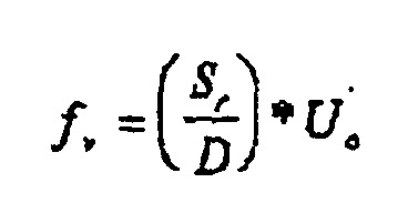
- this frequency f v can be represented by the following relation: wherein S r forms the Strouhal number determined by the shape of the object, D represents the diameter of the object, that is, the distance over which the fluid flow is interrupted by the object, and U o represents the approach velocity of the fluid flowing towards the object.
- the object of the invention is to obviate this disadvantage and to provide a device of the type described in the preamble which, also for random pulsations, still enables an accurate determination of this approach velocity.
- the device such as it is described in the preamble is characterized in that at least two objects of so different a shape and/or diameter are present that at least one of the vortex frequencies thereby determined is independent of a pulsation frequency possibly arising in the approach velocity of the fluid.
- the S r /D ratio for the two objects can be chosen to be so different that for a given pulsating approach velocity at least one of the two vortex frequencies has a value such that the f v /f p ratio comes to lie outside the interval (0.4, 2.5). Only from such a vortex frequency can a correct approach velocity be determined. Obviously, this requires the presence of a sensor to determine the pulsation frequency. In many cases, for both vortex frequencies the f v /f p ratio will lie outside this interval; in such a situation, by measurement of the vortex frequency in each of the two vortex streets, the same value for the approach velocity will be obtained. Although, of course, more than two objects may be placed in the pipe, this is basically unnecessary, and in practice only two objects will suffice.
- the two objects referred to can be arranged after each other, while choosing the mutual distance to be sufficiently great to keep any mutual interaction of the two objects as small as possible. Such interaction can also be minimized by arranging the two objects crosswise in the pipe.
- the objects can be arranged not only behind each other, but also next to each other, again subject to the requirement that their mutual distance be sufficiently great to reduce interaction between the objects to a minimum.
- Both the measurement of the vortex frequency and the measurement of the pulsation frequency are done by means of pressure sensors which are arranged at a suitable point on or in the wall of the pipe, although it is also possible for the sensors determining the vortex frequency to be arranged in or on the respective objects, since the vortices induce a force acting on the objects that can be measured. Further, it is possible to integrate the sensor for determining the pulsation frequency into one of the sensors or into both sensors for determining the vortex frequency.
- Fig. 1 shows a pipe 1, in which an object 2 is arranged.
- the object 2 extends throughout the diameter of pipe 1 and has a triangular cross section of a diameter D.
- a fluid of an approach velocity U 0 is led through pipe 1, a so-called Von Karman vortex street 3 develops over a certain length behind the object 2.
- the frequency with which the vortices in this vortex street are generated is determined by the shape and the diameter D of the object 2.
- This frequency f v is measured by a pressure sensor 4 on the inside wall of pipe 1.
- the above-mentioned approach velocity U 0 to be determined is proportional to the vortex frequency f v .
- the proportionality constant is determined by calibration with a known approach velocity.
- a first object 5 of a circular cross section and a diameter D 1 , and a second object 6 of a triangular cross section and a diameter D 2 have been arranged in pipe 1. Both objects extend throughout the diameter of the pipe, behind each other.
- the device is here provided with two sensors 7 and 8 for measuring the vortex frequencies f v1 and f v2 in the Von Karman vortex streets arising behind the respective objects.
- the shape and the diameter of the objects 5 and 6 are different, such that the S r1 /D 1 ratio differs from the S r2 /D 2 ratio to such an extent that the vortex frequencies differ by at least about a factor of 6.
- S r1 and S r2 are the Strouhal numbers of the objects 5 and 6, respectively.
- a pressure sensor 9 is present to enable determination of the pulsation frequency f p of the fluid flow.
- means 10 are present, for instance comprising a microprocessor, to determine the approach velocity from the signals coming from the pressure sensors 7, 8 and 9.
- the distance L between the objects should be chosen to be sufficiently large. Obviously, this distance will be dependent on the shape and diameter of the objects.
- Fig. 3 shows a second exemplary embodiment of the device according to the invention.
- the two objects 11 and 12 are here arranged in the pipe 1 so as to cross each other perpendicularly.
- the object 11 has a circular cross section, while the object 12 has a semicircular cross section; both objects again extend throughout the diameter of pipe 1.
- the shape and diameter of the objects here differ so much from each other again that, as in the first exemplary embodiment, the measured vortex frequencies differ by at least about a factor of 6.
- Fig. 4 shows two objects 13 and 14 arranged next to each other in the pipe.
- the objects have a circular and a triangular cross section, respectively, and different diameters, and extend parallel to each other in the pipe 1.
- the mutual distance l between the objects has been selected to be so large that any interaction between the objects is minimized.
- the shape and diameter of the two objects are so different again that the vortex frequencies in question differ by at least about a factor of 6.
- both the shape and the diameter of the two objects are different. Also possible, however, are embodiments where the shape alone or the diameter alone of the object is different.
- Fig. 5 gives an example of an embodiment in which the two objects have the same shape but differ in diameter.
- the two objects 15 and 16 are arranged next to each other here and form one whole 17 with each other.
- the pressure sensors for measuring the vortex frequencies are likewise arranged next to each other here. Owing to the different diameters of the objects 15 and 16, here too, again, vortex frequencies are measured that differ from each other by at least about a factor of 6.
- the invention is not limited to the exemplary embodiments presented here, but encompasses all kinds of modifications thereof, naturally insofar as they fall within the scope of protection of the appended claims.
- the sensors for determining the vortex frequencies it is possible for the sensors for determining the vortex frequencies to be arranged in or on the objects in question, instead of in or on the wall of pipe 1. It is also possible, as has already been mentioned before, to integrate the sensor for determining the pulsation frequency into a sensor for determining the vortex frequency. Further, all kinds of shapes and dimensions other than those presented here are possible, as long as the measured vortex frequencies differ from each other by such an amount that at least one of these frequencies is independent of a pulsation frequency that may arise in the approach velocity of the fluid.
Landscapes
- Physics & Mathematics (AREA)
- Fluid Mechanics (AREA)
- General Physics & Mathematics (AREA)
- Measuring Volume Flow (AREA)
- Indicating Or Recording The Presence, Absence, Or Direction Of Movement (AREA)
Abstract
Description
Claims (6)
- Device for measuring the volume flow of a fluid in a pipe (1), the device comprising a pipe (1), a first and a second object (5, 6; 11, 12; 13, 14; 15,16) with a different shape and/or diameter arranged in the pipe (1), a first sensor arranged in the pipe for determining a frequency with which vortices occur which arise behind the objects upon the fluid flowing round the objects, and means for determining the volume flow of the fluid from this frequency, characterized in that the device is provided with a second sensor(7, 8) arranged in the pipe, the first and the second sensor measuring the vortex frequencies (fv1 and fv2) corresponding with the first and the second object respectively, and a further sensor (9) in the pipe for determining the pulsation frequency possibly arising in the approach velocity of the fluid, the difference in shape and/or diameter of the objects being such that the vortex frequency of the first object is independent of the pulsation frequency at a pulsation frequency where the vortex frequency of the second object depends on the pulsation frequency and vice versa, the means for determining the volume flow determining the volume flow from a selected one of the vortex frequencies that is determined to be independent of the pulsation frequency.
- Device according to claim 1, characterized in that means (10) are provided, in which, in response to signals from the above sensors (7, 8 and 9), the approach velocity is determined from that vortex frequency, or those vortex frequencies, for which it holds that the ratio between the vortex frequency and the pulsation frequency lies outside the interval between 0.4 and 2.5.
- A device according to claim 1 or 2, characterized in that, seen in the flow direction, two objects (5, 6) arranged behind each other are present.
- A device according to claim 1 or 2, characterized in that, seen in the flow direction, (11, 12) two objects crossing each other are present.
- A device according to claim 1 or 2, characterized in that, seen in the flow direction, two objects (13, 14) located next to each other are present.
- A device according to claim 5, characterized in that, seen in the flow direction, the two objects (15, 16) located next to each other form one whole.
Applications Claiming Priority (3)
| Application Number | Priority Date | Filing Date | Title |
|---|---|---|---|
| NL1009797 | 1998-08-03 | ||
| NL1009797A NL1009797C2 (en) | 1998-08-03 | 1998-08-03 | Device for measuring the volume flow of a fluid in a pipe. |
| PCT/NL1999/000493 WO2000008420A1 (en) | 1998-08-03 | 1999-08-02 | Device for measuring the volume flow of a fluid in a pipe |
Publications (2)
| Publication Number | Publication Date |
|---|---|
| EP1102966A1 EP1102966A1 (en) | 2001-05-30 |
| EP1102966B1 true EP1102966B1 (en) | 2004-12-15 |
Family
ID=19767601
Family Applications (1)
| Application Number | Title | Priority Date | Filing Date |
|---|---|---|---|
| EP99937114A Expired - Lifetime EP1102966B1 (en) | 1998-08-03 | 1999-08-02 | Device for measuring the volume flow of a fluid in a pipe |
Country Status (9)
| Country | Link |
|---|---|
| US (1) | US6675661B1 (en) |
| EP (1) | EP1102966B1 (en) |
| JP (1) | JP4693990B2 (en) |
| AT (1) | ATE285065T1 (en) |
| AU (1) | AU5200399A (en) |
| DE (1) | DE69922663T2 (en) |
| ES (1) | ES2234280T3 (en) |
| NL (1) | NL1009797C2 (en) |
| WO (1) | WO2000008420A1 (en) |
Cited By (1)
| Publication number | Priority date | Publication date | Assignee | Title |
|---|---|---|---|---|
| WO2026049978A1 (en) * | 2024-08-26 | 2026-03-05 | Mozarc Medical Us Llc | Flow detector |
Families Citing this family (10)
| Publication number | Priority date | Publication date | Assignee | Title |
|---|---|---|---|---|
| EP1019338B1 (en) * | 1997-09-05 | 2002-12-11 | Frenton Limited | A method for producing abrasive grains and the abrasive grains produced by this method |
| DE10047603A1 (en) * | 2000-09-26 | 2002-04-11 | Siemens Ag | Flow meter such as for measuring air flow in an inlet channel of a combustion engine where eddy is generated dependent on the degree of pulsation of the flow |
| US20060052943A1 (en) * | 2004-07-28 | 2006-03-09 | Karthik Ramani | Architectures, queries, data stores, and interfaces for proteins and drug molecules |
| US7540172B2 (en) * | 2005-05-19 | 2009-06-02 | Chamilia, Llc | Apparatus for adjustable bead retention on bracelets and necklaces |
| JP5473719B2 (en) * | 2010-03-30 | 2014-04-16 | アズビル株式会社 | Vortex flow meter |
| US9010197B1 (en) | 2010-09-21 | 2015-04-21 | The United States Of America As Represented By The Secretary Of The Navy | System for amplifying flow-induced vibration energy using boundary layer and wake flow control |
| DE102010046667A1 (en) * | 2010-09-27 | 2012-03-29 | Airbus Operations Gmbh | Fluid actuator for influencing the flow along a flow surface and the blower and flow body with such a fluid actuator |
| DE102011050716B4 (en) * | 2011-05-30 | 2013-01-24 | Technische Universität Dresden | Method and device for the online measurement of the viscosity of a fluid |
| DE102015111642A1 (en) * | 2015-07-17 | 2017-01-19 | Endress+Hauser Flowtec Ag | Flowmeter according to the vortex meter principle |
| JP2019521350A (en) * | 2016-07-21 | 2019-07-25 | マイクロ・モーション・インコーポレーテッドMicro Motion Incorporated | Vortex flowmeter with reduced process penetration |
Family Cites Families (8)
| Publication number | Priority date | Publication date | Assignee | Title |
|---|---|---|---|---|
| GB2111681B (en) * | 1981-12-10 | 1985-09-11 | Itt Ind Ltd | Fluid flowmeter |
| US4782710A (en) * | 1986-04-30 | 1988-11-08 | Fuji Electric Co., Ltd. | Karman vortex flow meter |
| US4831883A (en) * | 1988-05-23 | 1989-05-23 | Itt Corporation | Double bluff body vortex meter |
| GB8915994D0 (en) * | 1989-07-12 | 1989-08-31 | Schlumberger Ind Ltd | Vortex flowmeters |
| US5247838A (en) * | 1991-12-19 | 1993-09-28 | Badger Meter, Inc. | Double wing vortex flowmeter |
| US6058787A (en) * | 1996-06-21 | 2000-05-09 | Hughes Technology Group L.L.C | Mass flow measuring device |
| EP0841545B1 (en) * | 1996-11-08 | 1999-04-28 | Endress + Hauser Flowtec AG | Vortex flow sensor |
| US6053053A (en) * | 1998-03-13 | 2000-04-25 | Rosemount Inc. | Multiple vortex flowmeter system |
-
1998
- 1998-08-03 NL NL1009797A patent/NL1009797C2/en not_active IP Right Cessation
-
1999
- 1999-08-02 US US09/744,566 patent/US6675661B1/en not_active Expired - Fee Related
- 1999-08-02 AT AT99937114T patent/ATE285065T1/en active
- 1999-08-02 DE DE69922663T patent/DE69922663T2/en not_active Expired - Lifetime
- 1999-08-02 JP JP2000564009A patent/JP4693990B2/en not_active Expired - Fee Related
- 1999-08-02 EP EP99937114A patent/EP1102966B1/en not_active Expired - Lifetime
- 1999-08-02 AU AU52003/99A patent/AU5200399A/en not_active Abandoned
- 1999-08-02 ES ES99937114T patent/ES2234280T3/en not_active Expired - Lifetime
- 1999-08-02 WO PCT/NL1999/000493 patent/WO2000008420A1/en not_active Ceased
Non-Patent Citations (1)
| Title |
|---|
| PETERS ET AL: "Impact of pulsations on vortex flowmeters", 15 June 1998 (1998-06-15) - 17 June 1998 (1998-06-17), pages 1 - 6 * |
Cited By (1)
| Publication number | Priority date | Publication date | Assignee | Title |
|---|---|---|---|---|
| WO2026049978A1 (en) * | 2024-08-26 | 2026-03-05 | Mozarc Medical Us Llc | Flow detector |
Also Published As
| Publication number | Publication date |
|---|---|
| DE69922663T2 (en) | 2005-10-06 |
| ES2234280T3 (en) | 2005-06-16 |
| NL1009797C2 (en) | 2000-02-04 |
| US6675661B1 (en) | 2004-01-13 |
| AU5200399A (en) | 2000-02-28 |
| EP1102966A1 (en) | 2001-05-30 |
| JP4693990B2 (en) | 2011-06-01 |
| DE69922663D1 (en) | 2005-01-20 |
| ATE285065T1 (en) | 2005-01-15 |
| WO2000008420A1 (en) | 2000-02-17 |
| JP2002522756A (en) | 2002-07-23 |
Similar Documents
| Publication | Publication Date | Title |
|---|---|---|
| US6003383A (en) | Vortex fluid meter incorporating a double obstacle | |
| US6675661B1 (en) | Device for measuring the volume flow of a fluid in a pipe | |
| JP6154069B2 (en) | Differential pressure based flow measurement device with improved pitot tube configuration | |
| EP0048588B1 (en) | Vortex-shedding flowmeter and method of measuring fluid flow | |
| EP2444781A1 (en) | Ultrasonic measurement of flow velocity | |
| DE102010056279B4 (en) | Vortex flowmeter with optimized temperature detection | |
| US3874234A (en) | Vortex shedding flowmeter | |
| CN108351239B (en) | Flow measuring device based on eddy current flow measuring principle | |
| US10488237B2 (en) | Measurement apparatus for measuring a flow rate of a fluid | |
| US10508940B2 (en) | Measuring device for fluids as well as fluidic system with a measuring device | |
| WO1994021989A1 (en) | Fluid flowmeter | |
| US8024136B2 (en) | Method for signal processing of measurement signals of a vortex flow transducer | |
| JP3119782B2 (en) | Flowmeter | |
| UA34492C2 (en) | Vortex flow-rate meter for fluid medium | |
| EP2657658A1 (en) | Ultrasonic flow measurement system | |
| US5965800A (en) | Method of calibrating an ultrasonic flow meter | |
| US10605635B2 (en) | Insertion vortex flowmeter element | |
| GB2434871A (en) | Determination of electrode impedance for an electromagnetic flow meter | |
| US20220065676A1 (en) | Vibronic measurement sensor having at least two temperature sensors | |
| JPH11316144A (en) | Differential pressure flow meter | |
| JPH0242319A (en) | Fluid measuring device | |
| RU2162206C2 (en) | Vortex register of fluid medium | |
| JP3142015B2 (en) | Vortex flow meter | |
| DE102017012066A1 (en) | Flow meter according to the vortex meter principle, measuring tube therefor and method for measuring the flow or the flow velocity of a medium | |
| Cousins et al. | Proving of multi-path liquid ultrasonic flowmeters |
Legal Events
| Date | Code | Title | Description |
|---|---|---|---|
| PUAI | Public reference made under article 153(3) epc to a published international application that has entered the european phase |
Free format text: ORIGINAL CODE: 0009012 |
|
| 17P | Request for examination filed |
Effective date: 20010206 |
|
| AK | Designated contracting states |
Kind code of ref document: A1 Designated state(s): AT BE CH CY DE DK ES FI FR GB GR IE IT LI LU MC NL PT SE |
|
| AX | Request for extension of the european patent |
Free format text: AL;LT;LV;MK;RO;SI |
|
| 17Q | First examination report despatched |
Effective date: 20020807 |
|
| RIN1 | Information on inventor provided before grant (corrected) |
Inventor name: PETERS, MARINUS, CAROLUS, ADRIANUS, MARIA |
|
| GRAP | Despatch of communication of intention to grant a patent |
Free format text: ORIGINAL CODE: EPIDOSNIGR1 |
|
| GRAP | Despatch of communication of intention to grant a patent |
Free format text: ORIGINAL CODE: EPIDOSNIGR1 |
|
| GRAS | Grant fee paid |
Free format text: ORIGINAL CODE: EPIDOSNIGR3 |
|
| GRAA | (expected) grant |
Free format text: ORIGINAL CODE: 0009210 |
|
| AK | Designated contracting states |
Kind code of ref document: B1 Designated state(s): AT BE CH CY DE DK ES FI FR GB GR IE IT LI LU MC NL PT SE |
|
| PG25 | Lapsed in a contracting state [announced via postgrant information from national office to epo] |
Ref country code: FI Free format text: LAPSE BECAUSE OF FAILURE TO SUBMIT A TRANSLATION OF THE DESCRIPTION OR TO PAY THE FEE WITHIN THE PRESCRIBED TIME-LIMIT Effective date: 20041215 |
|
| REG | Reference to a national code |
Ref country code: GB Ref legal event code: FG4D Ref country code: CH Ref legal event code: EP |
|
| REG | Reference to a national code |
Ref country code: IE Ref legal event code: FG4D |
|
| REF | Corresponds to: |
Ref document number: 69922663 Country of ref document: DE Date of ref document: 20050120 Kind code of ref document: P |
|
| PG25 | Lapsed in a contracting state [announced via postgrant information from national office to epo] |
Ref country code: SE Free format text: LAPSE BECAUSE OF FAILURE TO SUBMIT A TRANSLATION OF THE DESCRIPTION OR TO PAY THE FEE WITHIN THE PRESCRIBED TIME-LIMIT Effective date: 20050315 Ref country code: GR Free format text: LAPSE BECAUSE OF FAILURE TO SUBMIT A TRANSLATION OF THE DESCRIPTION OR TO PAY THE FEE WITHIN THE PRESCRIBED TIME-LIMIT Effective date: 20050315 |
|
| REG | Reference to a national code |
Ref country code: DK Ref legal event code: T3 |
|
| REG | Reference to a national code |
Ref country code: CH Ref legal event code: NV Representative=s name: PATENTANWAELTE SCHAAD, BALASS, MENZL & PARTNER AG |
|
| REG | Reference to a national code |
Ref country code: ES Ref legal event code: FG2A Ref document number: 2234280 Country of ref document: ES Kind code of ref document: T3 |
|
| PG25 | Lapsed in a contracting state [announced via postgrant information from national office to epo] |
Ref country code: LU Free format text: LAPSE BECAUSE OF NON-PAYMENT OF DUE FEES Effective date: 20050802 Ref country code: IE Free format text: LAPSE BECAUSE OF NON-PAYMENT OF DUE FEES Effective date: 20050802 Ref country code: CY Free format text: LAPSE BECAUSE OF FAILURE TO SUBMIT A TRANSLATION OF THE DESCRIPTION OR TO PAY THE FEE WITHIN THE PRESCRIBED TIME-LIMIT Effective date: 20050802 |
|
| PG25 | Lapsed in a contracting state [announced via postgrant information from national office to epo] |
Ref country code: MC Free format text: LAPSE BECAUSE OF NON-PAYMENT OF DUE FEES Effective date: 20050831 |
|
| PLBE | No opposition filed within time limit |
Free format text: ORIGINAL CODE: 0009261 |
|
| STAA | Information on the status of an ep patent application or granted ep patent |
Free format text: STATUS: NO OPPOSITION FILED WITHIN TIME LIMIT |
|
| 26N | No opposition filed |
Effective date: 20050916 |
|
| ET | Fr: translation filed | ||
| REG | Reference to a national code |
Ref country code: IE Ref legal event code: MM4A |
|
| PG25 | Lapsed in a contracting state [announced via postgrant information from national office to epo] |
Ref country code: PT Free format text: LAPSE BECAUSE OF NON-PAYMENT OF DUE FEES Effective date: 20050515 |
|
| PGFP | Annual fee paid to national office [announced via postgrant information from national office to epo] |
Ref country code: NL Payment date: 20100813 Year of fee payment: 12 Ref country code: ES Payment date: 20100825 Year of fee payment: 12 Ref country code: CH Payment date: 20100824 Year of fee payment: 12 |
|
| PGFP | Annual fee paid to national office [announced via postgrant information from national office to epo] |
Ref country code: IT Payment date: 20100823 Year of fee payment: 12 Ref country code: FR Payment date: 20100901 Year of fee payment: 12 Ref country code: DE Payment date: 20100823 Year of fee payment: 12 Ref country code: AT Payment date: 20100812 Year of fee payment: 12 |
|
| PGFP | Annual fee paid to national office [announced via postgrant information from national office to epo] |
Ref country code: GB Payment date: 20100819 Year of fee payment: 12 |
|
| PGFP | Annual fee paid to national office [announced via postgrant information from national office to epo] |
Ref country code: DK Payment date: 20100810 Year of fee payment: 12 |
|
| PGFP | Annual fee paid to national office [announced via postgrant information from national office to epo] |
Ref country code: BE Payment date: 20100810 Year of fee payment: 12 |
|
| BERE | Be: lapsed |
Owner name: NEDERLANDSE ORGANISATIE VOOR TOEGEPAST-NATUURWETEN Effective date: 20110831 |
|
| REG | Reference to a national code |
Ref country code: NL Ref legal event code: V1 Effective date: 20120301 |
|
| REG | Reference to a national code |
Ref country code: CH Ref legal event code: PL |
|
| GBPC | Gb: european patent ceased through non-payment of renewal fee |
Effective date: 20110802 |
|
| PG25 | Lapsed in a contracting state [announced via postgrant information from national office to epo] |
Ref country code: LI Free format text: LAPSE BECAUSE OF NON-PAYMENT OF DUE FEES Effective date: 20110831 Ref country code: CH Free format text: LAPSE BECAUSE OF NON-PAYMENT OF DUE FEES Effective date: 20110831 |
|
| REG | Reference to a national code |
Ref country code: DK Ref legal event code: EBP |
|
| REG | Reference to a national code |
Ref country code: FR Ref legal event code: ST Effective date: 20120430 |
|
| PG25 | Lapsed in a contracting state [announced via postgrant information from national office to epo] |
Ref country code: IT Free format text: LAPSE BECAUSE OF NON-PAYMENT OF DUE FEES Effective date: 20110802 Ref country code: NL Free format text: LAPSE BECAUSE OF NON-PAYMENT OF DUE FEES Effective date: 20120301 Ref country code: BE Free format text: LAPSE BECAUSE OF NON-PAYMENT OF DUE FEES Effective date: 20110831 |
|
| REG | Reference to a national code |
Ref country code: DE Ref legal event code: R119 Ref document number: 69922663 Country of ref document: DE Effective date: 20120301 |
|
| PG25 | Lapsed in a contracting state [announced via postgrant information from national office to epo] |
Ref country code: DK Free format text: LAPSE BECAUSE OF NON-PAYMENT OF DUE FEES Effective date: 20110831 |
|
| PG25 | Lapsed in a contracting state [announced via postgrant information from national office to epo] |
Ref country code: GB Free format text: LAPSE BECAUSE OF NON-PAYMENT OF DUE FEES Effective date: 20110802 Ref country code: FR Free format text: LAPSE BECAUSE OF NON-PAYMENT OF DUE FEES Effective date: 20110831 |
|
| REG | Reference to a national code |
Ref country code: ES Ref legal event code: FD2A Effective date: 20121207 |
|
| REG | Reference to a national code |
Ref country code: AT Ref legal event code: MM01 Ref document number: 285065 Country of ref document: AT Kind code of ref document: T Effective date: 20110802 |
|
| PG25 | Lapsed in a contracting state [announced via postgrant information from national office to epo] |
Ref country code: AT Free format text: LAPSE BECAUSE OF NON-PAYMENT OF DUE FEES Effective date: 20110802 |
|
| PG25 | Lapsed in a contracting state [announced via postgrant information from national office to epo] |
Ref country code: ES Free format text: LAPSE BECAUSE OF NON-PAYMENT OF DUE FEES Effective date: 20110803 |
|
| PG25 | Lapsed in a contracting state [announced via postgrant information from national office to epo] |
Ref country code: DE Free format text: LAPSE BECAUSE OF NON-PAYMENT OF DUE FEES Effective date: 20120301 |