EP1102511A1 - Method for a handover between different nodes in a mobile communication system - Google Patents
Method for a handover between different nodes in a mobile communication system Download PDFInfo
- Publication number
- EP1102511A1 EP1102511A1 EP99122660A EP99122660A EP1102511A1 EP 1102511 A1 EP1102511 A1 EP 1102511A1 EP 99122660 A EP99122660 A EP 99122660A EP 99122660 A EP99122660 A EP 99122660A EP 1102511 A1 EP1102511 A1 EP 1102511A1
- Authority
- EP
- European Patent Office
- Prior art keywords
- switching node
- base station
- user equipment
- connection
- protocol
- Prior art date
- Legal status (The legal status is an assumption and is not a legal conclusion. Google has not performed a legal analysis and makes no representation as to the accuracy of the status listed.)
- Withdrawn
Links
Images


Classifications
-
- H—ELECTRICITY
- H04—ELECTRIC COMMUNICATION TECHNIQUE
- H04W—WIRELESS COMMUNICATION NETWORKS
- H04W36/00—Hand-off or reselection arrangements
- H04W36/12—Reselecting a serving backbone network switching or routing node
Definitions
- the present invention relates to a method according to the preamble of claim 1.
- a switching node and a program are described.
- Customary base station subsystems comprise one or several base stations for the wireless connection to the user equipment and a base station controller which controls the base stations and connects them to the core network of the communication system.
- the controller can be for example a base station controller (BSC) as defined in GSM or a radio network controller (RNC) for a base station subsystem according to the UMTS standard.
- BSC base station controller
- RNC radio network controller
- a base station subsystem i.e. the controller, is in turn controlled by a switching node, e. g. a mobile switching center (MSC).
- a switching node is connectable or permanently connected to a base station subsystem with a protocol corresponding to the connection specification used between the base station subsystem and the user equipment.
- the RANAP Radio Access Network Application Protocol
- BSSMAP Base Station System Management Application Part
- an MSC in a GSM system generally exchanges only BSSMAP messages with a BSC while a 3G MSC in a UMTS system processes RANAP messages.
- a 3G MSC can normally also process BSSMAP messages and can be connected to a BSC according to GSM specifications over an A interface .
- a handover is necessary between base station subsystems which are controlled by different switching nodes.
- the switching nodes exchange messages to perform the handover procedure of the user equipment from the first base station subsystem to the second base station subsystem which is controlled by a second switching node.
- the messages are described in 3GPP technical specification 3G TS 29.010 V 3.0.0. They encapsulate a set of parameters used in the protocol between the switching nodes and the base station subsystem.
- the set is necessary to perform the handover and comprises an identification of the connection for which the handover is to be executed and parameters which are required to provide defined services to the user.
- the necessary parameters for different types of connections, especially speech and data connections can differ.
- MAP Mobile Application Part
- 3GPP Technical Specification 29.002 V 3.2.0 3GPP Technical Specification 29.002 V 3.2.0 are suitable which allow to encapsulate BSSMAP messages.
- the parameter set is generated in the first switching node serving the user equipment from a message which is transmitted from the user equipment to the first switching node.
- the latter message which is generally in the DTAP (Direct Transfer Application Part) protocol is forwarded by the first base station subsystem without evaluation.
- connection specifications e.g. according to the standards for the GSM and UMTS air interfaces.
- User equipment which can set up connections according to further standards, e.g. DECT (Digital European Cordless Telecommunications) or WLAN (Wireless Local Area Network), in addition to at least one of these or other connection specifications is also possible.
- DECT Digital European Cordless Telecommunications
- WLAN Wireless Local Area Network
- many communication systems comprise base station subsystems for connection to the user equipment wherein different subsystems use different connection specifications on the interface to the user equipment.
- the necessary parameters in the set used in the protocol between a switching node and a base station subsystem are dependent on the connection specification between the user equipment and the base station subsystem because the protocol is adapted to the connection specification, i.e. the interface between base station and user equipment.
- the messages over a specific interface comprise mandatory fields which have to be filled in from the parameter set.
- Parameter sets for different protocols comprise different mandatory parameters. Consequently, the connection will be lost in an intersystem handover if the parameters necessary for the handover are not provided. This problem is aggravated if the movements of the user require a repeated handover between connections of different specifications. An additional problem is that the handover between different switching nodes requires a considerable time which can also lead to a disruption of the connection.
- the first switching node determines from a message transmitted from the user equipment whether the user equipment is capable of connections according to different specifications.
- the user equipment can be for example a mobile phone, a personal digital assistant (PDA) or a palmtop computer which is connectable to the communication network according to different specifications, e.g. with a GSM or UTRAN (UMTS Terrestrial Radio Access Network) and a WLAN connection.
- the evaluated message is a DTAP message from the user equipment to the first switching node during the idle mode of the user equipment before a connection or during the establishment of the connection.
- the evaluated message can be the message which is used for the generation of the parameter set transmitted in the handover procedure.
- the first switching node selects the parameter set encapsulated in the message to the second switching node according to the protocol for the connection of the second switching node to the target base station subsystem, i.e. the subsystem to which the handover procedure of the user equipment is performed. If both base station subsystems use the same connection specification on the interface to the user, the protocol corresponding to this connection specification is selected and encapsulated in the messages between the switching nodes. Else the selection depends on the implementations described below. It is either possible to generate only the selected parameter set or to generate different parameter sets and select one of them for encapsulation.
- a MAP message can enclose different message types it is sufficient for this purpose to amend the list of allowed message types for encapsulation in MAP messages by the specific type.
- the message type contained in the MAP message is indicated by a data field in the header of the MAP message which can then be set to the specific message type enclosed from the amended list.
- RANAP messages or further message specifications can be encapsulated into a MAP message and processed by the target switching node.
- the proposed method has the advantage that it is simple to implement and ensures a safe execution of the handover procedure.
- the selection of the parameter set ensures that the target base station subsystem is provided with the parameters necessary for the establishment of the connection to the user equipment. Disruptions of a connection due to a handover of the user equipment between base station subsystems using different connection specifications are avoided.
- the first switching node serving the user equipment generates parameter sets for different protocols.
- a parameter set corresponding to every connection specification to which a handover is possible is generated.
- the parameter sets are stored in the first switching node.
- the parameter set according to the target base station subsystem is encapsulated in the message and sent to the target switching node. In this way, the time for the execution of the handover is reduced and the risk for a disruption of a connection during handover is diminished.
- the first switching node serving the user equipment generates all parameter sets from a message transmitted from the user equipment.
- a mapping between parameter sets for different types of messages for example BSSMAP and RANAP messages.
- An advantage is that those parameters which are defined only in one of the messages are not lost during the mapping procedure and need not to be replaced by default values.
- a switching node maps the parameter set for one protocol from a parameter set for a different protocol.
- the mapping can either be performed in the switching node first serving the user or in the target switching node of a handover.
- the latter embodiment is preferable if only a small number of nodes is connected to base station subsystems of a defined specification, for example base stations for a connection specification used mainly for indoor cells like the DECT or WLAN standards. Adaptations of other control nodes in the communication system to the specific specification can be avoided.
- all messages encapsulating parameter sets to further switching nodes in subsequent handover procedures are sent from the first switching node, i.e. the first node serves as an anchor node. Consequently, the parameters for every handover of a connection between different switching nodes are sent from the node which first served the user equipment in the connection.
- the embodiment is especially suitable if the parameter sets are generated in the first node from a message originating directly, i.e. without mapping, from the user equipment.
- the latter embodiment is also suitable, if the second and the further switching node are identical or collocated and control base station subsystems using different protocols. In this way a mapping in the further handover with a corresponding loss of information is avoided. If the first switching node serves as anchor node of the connection, the signaling load in the communication system is only slightly increased as every subsequent handover is communicated to the anchoring node.
- the parameter set encapsulated in the message between the switching nodes corresponds preferably to the protocol used between the second switching node and the second base station subsystem. In this way, the target switching node can relay the encapsulated parameter set without change of the protocol in a minimum time.
- a suitable message is a MAP message encapsulating a BSSMAP massage with the parameter set.
- a MAP message encapsulates a RANAP message comprising the parameter set.
- Advantages of this embodiment are the short length of the messages between the switching nodes and that all parameter sets can be generated in the first switching node serving the user equipment out of the parameters sent by the user equipment, e.g. in a DTAP message.
- the parameter set is sent according to a predefined protocol which can be processed by any switching node in the communication system.
- the predefined protocol is a protocol which is already used in all switching nodes of the system.
- the preferable predefined protocol is the BSSMAP protocol.
- the receiving switching node maps the parameter set to the protocol for the control of the second base station subsystem. Generally, a mapping is performed only in the target node.
- the embodiment is advantageous if base station subsystems according to an additional communication specification or only few base station subsystems according to a specific communication specification are connected to the communication system because only the switching nodes connectable to these base station subsystems need to perform a mapping.
- the protocol between the switching nodes needs not to be changed.
- the flexibility of this embodiment is limited by the parameters in the set according to the default protocol.
- the parameter set is sent for the predefined protocol and a parameter set for a further protocol is encapsulated in an extension field of the predefined protocol if the further protocol is used between the target switching node and the target base station subsystem. It is possible to encapsulate the parameter set for the further protocol in a message according to the further protocol which is in turn encapsulated in the extension field. This simplifies the handling of the parameters in the target switching node. If the predefined protocol is used between the target switching node and the target base station subsystem no parameters for a further protocol need to be encapsulated.
- the BSSMAP message comprises an extension field which can contain a RANAP message or the parameters according to a RANAP message.
- the MAP message between the switching nodes encapsulates a BSSMAP message with a further RANAP message or a RANAP parameter set encapsulated in the extension field of a BSSMAP message.
- the handover is performed to a base station subsystem controlled by a BSC, the MAP message between the switching nodes encapsulates an ordinary BSSMAP message. In this way all necessary parameters are transferred to the second or further switching node at the expense of an increased length of the messages.
- the target node performs a message extraction or a mapping to the message according to the required specification for the base station subsystem.
- a first group of parameters have to be set to default values in a mapping between the parameter sets while other parameters are identical in both sets or can be calculated from parameters in the other set without loss of information.
- the first group of parameters according to the further protocol is encapsulated in the extension field.
- the target switching node performs a mapping from the predefined protocol to the protocol for the control of the second base station subsystem.
- the preferable handling depends on the computing expense and additional length of the messages, i.e. these parameters can be either mapped or included in the extension field.
- a preferable switching node can be used in a mobile communications system with further switching nodes and user equipment connectable to base station subsystems according to different connection specifications.
- the switching node comprises means for the control of a first base station subsystem and a first interface for the connection to the first base station subsystem with a protocol corresponding to the connection specification used on the interface between the base station subsystem and the user equipment.
- a second interface is provided for the exchange of messages with at least one further switching node in a handover procedure of user equipment from the first base station subsystem to a second base station subsystem which is controlled by the further switching node.
- the message can encapsulate a parameter set for the connection protocol between the second base station subsystem and the further switching node.
- the switching node has furthermore means to generate the parameter set from a message which is transmitted from the user equipment and means to detect out of this or a different message transmitted from the user equipment whether the user equipment is capable of connections according to different connection specifications on the interface to a base station subsystem.
- the switching node selects the parameter set encapsulated in the message to the second switching node according to the protocol for the connection of the second switching node to the base station subsystem to which the handover procedure of the user equipment is performed. It is possible to select which set is generated for encapsulation or select a set from several ones generated before.
- the switching node comprises a processor system which allows to embody all of the means described as software programs.
- the switching node comprises means to generate parameter sets for different protocols and a memory to store the sets. This embodiment allows a reduced handover duration.
- a preferable node comprises means to generate parameter sets from a message transmitted from the user equipment or means to map the parameter set for one protocol to a parameter set for a different protocol.
- the switching node comprises means to encapsulate a parameter set for a first connection specification into a message for a second connection specification and/or to extract a parameter set for a first connection specification out of a message for a second connection specification.
- the encapsulated parameter set may be a subset of the parameters necessary for the handover if remaining parameters can be mapped from the message according to the second specification.
- messages of the second specification can be used, especially as default message type, without loosing information in mapping procedures and with reduced restrictions from limitations of the second connection specification.
- a program unit according to the invention can be stored on a data carrier or be loadable into a switching node for the control of base station subsystems in a communication system.
- the program unit is preferably part of a program which is executed in the handover of user equipment from a first base station subsystem to a second base station subsystem which is controlled by a second switching node in a communication system comprising base station subsystems differing in the connection specification on the interface to the user equipment.
- the switching node controls a base station subsystem with a protocol corresponding to the connection specification for the interface between the base station subsystem and the user equipment.
- the program unit comprises means, e.g.
- routines or subroutines to exchange messages in the handover procedure with the second switching node, said message encapsulating a parameter set for one of said protocols and means to generate the parameter set from a message which is transmitted from the user equipment to the switching node.
- the program unit checks a message transmitted from the user equipment whether the user equipment is capable of connections according to different specifications. It selects the parameter set encapsulated in the message to the second switching node according to the protocol for the connection of the second switching node to the base station subsystem to which the handover procedure of the user equipment is performed.
- the program unit can perform any steps of the methods described above.
- user equipment UE is connected to a first base station subsystem which is controlled by a radio network controller RNC1.
- the controller RNC1 is in turn connected to a switching node 3G MSC1 with a connection 1 over an lu interface. Over the lu interface, RANAP messages between the switching node 3G MSC and the controller RNC1 and DTAP messages can be exchanged. DTAP messages are sent between the switching node and the user equipment UE and forwarded by the controller RNC1 without evaluation.
- the DTAP messages comprise an indication which connection specifications can be processed by the user equipment.
- the control node 3G MSC1 When a DTAP message sent by the user equipment UE indicates, that the equipment can process different connection specifications used in the communication system, the control node 3G MSC1 generates and stores parameter sets for a handover to base station subsystems which use these specifications for connection to the user equipment.
- BSSMAP messages are used when the connection on the interface to the user equipment corresponds to the GSM standard, i.e. the controller is denoted as BSC
- RANAP messages are used if the connection corresponds to the UMTS standard, i.e. the controller is denoted as RNC.
- a node which is denoted as 3G MSC can process both RANAP messages and BSSMAP messages in addition to DTAP messages while a GSM MSC processes only BSSMAP messages in addition to DTAP messages.
- a handover of the connection to the second base station subsystem is performed.
- the handover is executed by the following signaling sequence wherein the connection over which the message is sent is denoted in brackets and the message types are used as in proposed specification 3G TS 29.010 V 3.0.0:
- the target base station system for the handover is indicated as target base station subsystem or as target cell. Therefore, the switching node 3G MSC1 is provided with the information which protocol is used on the connection 3 between the switching node GSM MSC2 and the target controller BSC 2.
- the controller BSC2 corresponds to the GSM standard and BSSMAP messages sent over a GSM A interface are used on the connection 3. Therefore, the MAP PREPARE HANDOVER REQUEST (HANDOVER REQUEST) comprises a parameter set for the execution of the handover which is selected according to the protocol on connection 3.
- the parameter set for a BSSMAP message is selected from the memory of switching node 3G MSC 1 and encapsulated in the MAP message on connection 2.
- the encapsulated message type is indicated in a box stacked on the box denoting the connection and protocol type used on the respective connection.
- the message MAP PREPARE SUBSEQUENT HANDOVER REQUEST (HANDOVER REQUEST) is sent to the switching node 3G MSC1. Because the target base station system for the handover indicated in this message is the controller BSC3 corresponding to the GSM standard, BSSMAP messages sent over a GSM A interface are used on the connection 5. The parameter set for the execution of the handover is selected in the switching node 3G MSC1 according to the protocol on connection 5.
- the parameter set for a BSSMAP message is selected from the memory of switching node 3G MSC 1 and encapsulated in the MAP PREPARE HANDOVER REQUEST (HANDOVER REQUEST) on connection 4.
- HANDOVER REQUEST HANDOVER REQUEST
- additional handover procedures are also performed between base station systems served by the same switching node. The execution of the latter handover procedures as well as the execution of those steps of the handover procedures performed in the base station subsystems to execute the commands received by the control nodes are known to a skilled person.
- FIG 2 a second example for a handover sequence according to the invention is depicted for a different arrangement of control nodes.
- a first handover from a first base station subsystem with controller RNC11 using a UMTS air interface specification for the connection with the user equipment to a second base station subsystem with controller BSC12 using a GSM air interface specification for the connection to the user equipment the following messaging sequence is executed.
- the links over which the messages are sent are indicated in brackets.
- the switching nodes GSM MSC12 and 3G MSC13 controlling the nodes are collocated or different logical nodes in a single physical node, i.e. the switching nodes GSM MSC12 and 3G MSC13 can be different interfaces of a single device.
- FIG 3 an example for a handover sequence according to the invention is depicted for a further arrangement of control nodes.
- the first base station subsystem with controller BSC21 using a GSM air interface specification for the connection to the user equipment is connected to the controlling node 3G MSC 21 over a connection 21 on which BSSMAP messages are sent over A interfaces.
- the controlling node 3G MSC 21 can also process RANAP messages.
- the following messaging sequence is executed.
- the MAP PREPARE HANDOVER REQUEST (RELOCATION REQUEST) on connection 22 comprises a RANAP message according to the RANAP protocol used on the connection 23 between 3G MSC 22 and RNC 22. As before, the links over which the messages are sent are indicated in brackets.
- MAP PREPARE HANDOVER REQUEST HANDOVER REQUEST
- BSSMAP message with the parameter set for connection 25:
- any handover sequence between any combination of base station subsystems according to GSM and UMTS specifications can be performed.
- all switching nodes and base station subsystem controllers correspond to UMTS specifications and can process RANAP messages, preferably on all connections between the switching nodes and the base station subsystem controllers RANAP messages are used while on all links between switching nodes, MAP messages encapsulating RANAP messages are preferable.
Abstract
In a method for a handover of user equipment (UE) in a mobile communication
system from a first base station subsystem controlled by a first switching node (3G
MSC 1) to a second base station subsystem which is controlled by a second
switching node (GSM MSC 2), user equipment (UE) capable of connections to
base stations according to at least two connection specifications and the
communication system comprises different base station subsystems for connection
to the user equipment (UE) using one of said specifications. The second switching
node (GSM MSC 2) controls the second base station subsystem using a protocol
corresponding to the connection specification used on the interface between the
base station subsystem and the user equipment (UE). The switching nodes (3G
MSC 1, GSM MSC 2) exchange messages in the handover procedure which
encapsulate a parameter set for one of said protocols and the parameter set is
generated in the first switching node (3G MSC 1) from a message which is
transmitted from the user equipment (UE) to the first switching node (3G MSC 1).
The first switching node (3G MSC 1) detects out of a message transmitted from the
user equipment (UE) whether the user equipment (UE) is capable of connections
according to different specifications and selects the parameter set encapsulated in
the message to the second switching node (GSM MSC 2) according to the protocol
for the connection of the second switching node (GSM MSC 2) to the second base
station subsystem. Furthermore, a switching nodes and programs embodying the
invention are described.
Description
- The present invention relates to a method according to the preamble of
claim 1. In addition, a switching node and a program are described. - When a user moves through a cellular communication system or requests a connection with different parameters it is often necessary to perform a handover of user equipment from a first base station subsystem in the communication system to a second base station subsystem. In the handover, a connection of the user equipment, e.g. a mobile phone, to the second base station subsystem is established and the connection to the first base station subsystem is generally released. Customary base station subsystems comprise one or several base stations for the wireless connection to the user equipment and a base station controller which controls the base stations and connects them to the core network of the communication system. The controller can be for example a base station controller (BSC) as defined in GSM or a radio network controller (RNC) for a base station subsystem according to the UMTS standard.
- A base station subsystem, i.e. the controller, is in turn controlled by a switching node, e. g. a mobile switching center (MSC). A switching node is connectable or permanently connected to a base station subsystem with a protocol corresponding to the connection specification used between the base station subsystem and the user equipment. For a connection according to the UMTS standard, the RANAP (Radio Access Network Application Protocol) protocol is exchanged over the lu interface between the switching node and the controller in the base station subsystem while GSM subsystems use the BSSMAP (Base Station System Management Application Part) protocol over the A interface to the switching node. Correspondingly, an MSC in a GSM system generally exchanges only BSSMAP messages with a BSC while a 3G MSC in a UMTS system processes RANAP messages. A 3G MSC can normally also process BSSMAP messages and can be connected to a BSC according to GSM specifications over an A interface .
- Frequently, a handover is necessary between base station subsystems which are controlled by different switching nodes. In this case, the switching nodes exchange messages to perform the handover procedure of the user equipment from the first base station subsystem to the second base station subsystem which is controlled by a second switching node. The messages are described in 3GPP
technical specification 3G TS 29.010 V 3.0.0. They encapsulate a set of parameters used in the protocol between the switching nodes and the base station subsystem. The set is necessary to perform the handover and comprises an identification of the connection for which the handover is to be executed and parameters which are required to provide defined services to the user. The necessary parameters for different types of connections, especially speech and data connections can differ. - For communication between switching nodes and transfer of the parameter set, MAP (Mobile Application Part) messages as described in 3GPP Technical Specification 29.002 V 3.2.0 are suitable which allow to encapsulate BSSMAP messages. The parameter set is generated in the first switching node serving the user equipment from a message which is transmitted from the user equipment to the first switching node. The latter message which is generally in the DTAP (Direct Transfer Application Part) protocol is forwarded by the first base station subsystem without evaluation.
- On the interface to the base station subsystem, user equipment is often capable of a connection according to at least two connection specifications, e.g. according to the standards for the GSM and UMTS air interfaces. User equipment which can set up connections according to further standards, e.g. DECT (Digital European Cordless Telecommunications) or WLAN (Wireless Local Area Network), in addition to at least one of these or other connection specifications is also possible. Correspondingly, many communication systems comprise base station subsystems for connection to the user equipment wherein different subsystems use different connection specifications on the interface to the user equipment.
- The necessary parameters in the set used in the protocol between a switching node and a base station subsystem are dependent on the connection specification between the user equipment and the base station subsystem because the protocol is adapted to the connection specification, i.e. the interface between base station and user equipment. The messages over a specific interface comprise mandatory fields which have to be filled in from the parameter set. Parameter sets for different protocols comprise different mandatory parameters. Consequently, the connection will be lost in an intersystem handover if the parameters necessary for the handover are not provided. This problem is aggravated if the movements of the user require a repeated handover between connections of different specifications. An additional problem is that the handover between different switching nodes requires a considerable time which can also lead to a disruption of the connection.
- It is therefore an object of the present invention to obviate these disadvantages and provide a method for the handover between base station subsystems controlled by different switching nodes which provides the target subsystem with the required parameters for the handover. It is a further object, to provide a method which is simple and easy to implement. It is still another object to provide a method which performs the handover in a short time.
- According to the invention, the methods described in the claims are performed. Furthermore, the invention is embodied in switching nodes and software programs as described in the claims.
- In the proposed method, the first switching node determines from a message transmitted from the user equipment whether the user equipment is capable of connections according to different specifications. The user equipment can be for example a mobile phone, a personal digital assistant (PDA) or a palmtop computer which is connectable to the communication network according to different specifications, e.g. with a GSM or UTRAN (UMTS Terrestrial Radio Access Network) and a WLAN connection. Preferably, the evaluated message is a DTAP message from the user equipment to the first switching node during the idle mode of the user equipment before a connection or during the establishment of the connection. The evaluated message can be the message which is used for the generation of the parameter set transmitted in the handover procedure.
- The first switching node selects the parameter set encapsulated in the message to the second switching node according to the protocol for the connection of the second switching node to the target base station subsystem, i.e. the subsystem to which the handover procedure of the user equipment is performed. If both base station subsystems use the same connection specification on the interface to the user, the protocol corresponding to this connection specification is selected and encapsulated in the messages between the switching nodes. Else the selection depends on the implementations described below. It is either possible to generate only the selected parameter set or to generate different parameter sets and select one of them for encapsulation.
- It is often suitable to encapsulate the set of parameters in a specific message type, e.g. a RANAP message, for which the encapsulation into a MAP message is not defined in present standards. However, because a MAP message can enclose different message types it is sufficient for this purpose to amend the list of allowed message types for encapsulation in MAP messages by the specific type. The message type contained in the MAP message is indicated by a data field in the header of the MAP message which can then be set to the specific message type enclosed from the amended list. In this way, also RANAP messages or further message specifications can be encapsulated into a MAP message and processed by the target switching node.
- The proposed method has the advantage that it is simple to implement and ensures a safe execution of the handover procedure. The selection of the parameter set ensures that the target base station subsystem is provided with the parameters necessary for the establishment of the connection to the user equipment. Disruptions of a connection due to a handover of the user equipment between base station subsystems using different connection specifications are avoided.
- In a preferred embodiment, the first switching node serving the user equipment generates parameter sets for different protocols. Advantageously, a parameter set corresponding to every connection specification to which a handover is possible is generated. The parameter sets are stored in the first switching node. Upon the request of a handover to a target base station subsystem controlled by the target node, the parameter set according to the target base station subsystem is encapsulated in the message and sent to the target switching node. In this way, the time for the execution of the handover is reduced and the risk for a disruption of a connection during handover is diminished.
- Preferably, the first switching node serving the user equipment generates all parameter sets from a message transmitted from the user equipment. In this way, a mapping between parameter sets for different types of messages, for example BSSMAP and RANAP messages, is avoided. An advantage is that those parameters which are defined only in one of the messages are not lost during the mapping procedure and need not to be replaced by default values.
- Alternatively, a switching node maps the parameter set for one protocol from a parameter set for a different protocol. The mapping can either be performed in the switching node first serving the user or in the target switching node of a handover. The latter embodiment is preferable if only a small number of nodes is connected to base station subsystems of a defined specification, for example base stations for a connection specification used mainly for indoor cells like the DECT or WLAN standards. Adaptations of other control nodes in the communication system to the specific specification can be avoided.
- Preferably, all messages encapsulating parameter sets to further switching nodes in subsequent handover procedures are sent from the first switching node, i.e. the first node serves as an anchor node. Consequently, the parameters for every handover of a connection between different switching nodes are sent from the node which first served the user equipment in the connection. The embodiment is especially suitable if the parameter sets are generated in the first node from a message originating directly, i.e. without mapping, from the user equipment.
- The latter embodiment is also suitable, if the second and the further switching node are identical or collocated and control base station subsystems using different protocols. In this way a mapping in the further handover with a corresponding loss of information is avoided. If the first switching node serves as anchor node of the connection, the signaling load in the communication system is only slightly increased as every subsequent handover is communicated to the anchoring node.
- The parameter set encapsulated in the message between the switching nodes corresponds preferably to the protocol used between the second switching node and the second base station subsystem. In this way, the target switching node can relay the encapsulated parameter set without change of the protocol in a minimum time. If for example the handover is performed to a base station subsystem controlled by a BSC, a suitable message is a MAP message encapsulating a BSSMAP massage with the parameter set. In case of a handover to a base station subsystem controlled by an RNC, preferably a MAP message encapsulates a RANAP message comprising the parameter set. Advantages of this embodiment are the short length of the messages between the switching nodes and that all parameter sets can be generated in the first switching node serving the user equipment out of the parameters sent by the user equipment, e.g. in a DTAP message.
- Alternatively, the parameter set is sent according to a predefined protocol which can be processed by any switching node in the communication system. If the communication system is updated and a new type of protocol introduced the predefined protocol is a protocol which is already used in all switching nodes of the system. For example, in a GSM system which is updated with UMTS nodes and comprises both types of nodes, the preferable predefined protocol is the BSSMAP protocol. The receiving switching node maps the parameter set to the protocol for the control of the second base station subsystem. Generally, a mapping is performed only in the target node. The embodiment is advantageous if base station subsystems according to an additional communication specification or only few base station subsystems according to a specific communication specification are connected to the communication system because only the switching nodes connectable to these base station subsystems need to perform a mapping. The protocol between the switching nodes needs not to be changed. The flexibility of this embodiment is limited by the parameters in the set according to the default protocol.
- In a further alternative, the parameter set is sent for the predefined protocol and a parameter set for a further protocol is encapsulated in an extension field of the predefined protocol if the further protocol is used between the target switching node and the target base station subsystem. It is possible to encapsulate the parameter set for the further protocol in a message according to the further protocol which is in turn encapsulated in the extension field. This simplifies the handling of the parameters in the target switching node. If the predefined protocol is used between the target switching node and the target base station subsystem no parameters for a further protocol need to be encapsulated. As an example, the BSSMAP message comprises an extension field which can contain a RANAP message or the parameters according to a RANAP message. If the predefined protocol is the BSSMAP protocol and the handover is performed to a base station subsystem controlled by an RNC, the MAP message between the switching nodes encapsulates a BSSMAP message with a further RANAP message or a RANAP parameter set encapsulated in the extension field of a BSSMAP message. If the handover is performed to a base station subsystem controlled by a BSC, the MAP message between the switching nodes encapsulates an ordinary BSSMAP message. In this way all necessary parameters are transferred to the second or further switching node at the expense of an increased length of the messages. The target node performs a message extraction or a mapping to the message according to the required specification for the base station subsystem.
- Generally, in sets of parameters corresponding to different protocols a first group of parameters have to be set to default values in a mapping between the parameter sets while other parameters are identical in both sets or can be calculated from parameters in the other set without loss of information. To reduce the number of parameters in the extension field and the length of the message containing the parameter set, the first group of parameters according to the further protocol is encapsulated in the extension field. For parameters which are identical in both parameter sets the target switching node performs a mapping from the predefined protocol to the protocol for the control of the second base station subsystem. For parameters which can be calculated from parameters in the other set, the preferable handling depends on the computing expense and additional length of the messages, i.e. these parameters can be either mapped or included in the extension field.
- A preferable switching node can be used in a mobile communications system with further switching nodes and user equipment connectable to base station subsystems according to different connection specifications. The switching node comprises means for the control of a first base station subsystem and a first interface for the connection to the first base station subsystem with a protocol corresponding to the connection specification used on the interface between the base station subsystem and the user equipment. A second interface is provided for the exchange of messages with at least one further switching node in a handover procedure of user equipment from the first base station subsystem to a second base station subsystem which is controlled by the further switching node. The message can encapsulate a parameter set for the connection protocol between the second base station subsystem and the further switching node. The switching node has furthermore means to generate the parameter set from a message which is transmitted from the user equipment and means to detect out of this or a different message transmitted from the user equipment whether the user equipment is capable of connections according to different connection specifications on the interface to a base station subsystem. The switching node selects the parameter set encapsulated in the message to the second switching node according to the protocol for the connection of the second switching node to the base station subsystem to which the handover procedure of the user equipment is performed. It is possible to select which set is generated for encapsulation or select a set from several ones generated before. Generally, the switching node comprises a processor system which allows to embody all of the means described as software programs.
- Preferably, the switching node comprises means to generate parameter sets for different protocols and a memory to store the sets. This embodiment allows a reduced handover duration.
- Furthermore, a preferable node comprises means to generate parameter sets from a message transmitted from the user equipment or means to map the parameter set for one protocol to a parameter set for a different protocol.
- It is proposed that the switching node comprises means to encapsulate a parameter set for a first connection specification into a message for a second connection specification and/or to extract a parameter set for a first connection specification out of a message for a second connection specification. The encapsulated parameter set may be a subset of the parameters necessary for the handover if remaining parameters can be mapped from the message according to the second specification. Correspondingly, messages of the second specification can be used, especially as default message type, without loosing information in mapping procedures and with reduced restrictions from limitations of the second connection specification.
- A program unit according to the invention can be stored on a data carrier or be loadable into a switching node for the control of base station subsystems in a communication system. The program unit is preferably part of a program which is executed in the handover of user equipment from a first base station subsystem to a second base station subsystem which is controlled by a second switching node in a communication system comprising base station subsystems differing in the connection specification on the interface to the user equipment. The switching node controls a base station subsystem with a protocol corresponding to the connection specification for the interface between the base station subsystem and the user equipment. The program unit comprises means, e.g. routines or subroutines, to exchange messages in the handover procedure with the second switching node, said message encapsulating a parameter set for one of said protocols and means to generate the parameter set from a message which is transmitted from the user equipment to the switching node. The program unit checks a message transmitted from the user equipment whether the user equipment is capable of connections according to different specifications. It selects the parameter set encapsulated in the message to the second switching node according to the protocol for the connection of the second switching node to the base station subsystem to which the handover procedure of the user equipment is performed. The program unit can perform any steps of the methods described above.
- The foregoing and other objects, features and advantages of the present invention will become more apparent in the following detailed description of preferred embodiments as illustrated in the accompanying drawings.
-
- Fig. 1
- shows a schematic representation of nodes in a communication system wherein a method according to the invention is performed.
- Fig. 2
- shows a schematic representation of an alternative arrangement of nodes in a communication system wherein a method according to the invention is performed.
- Fig. 3
- shows a schematic representation of a further arrangement of nodes in a communication system wherein a method according to the invention is performed.
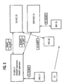
- In the communication system depicted in figure 1, user equipment UE is connected to a first base station subsystem which is controlled by a radio network controller RNC1. To simplify the drawing, only the controller in the base station system is shown. The controller RNC1 is in turn connected to a switching
node 3G MSC1 with aconnection 1 over an lu interface. Over the lu interface, RANAP messages between the switchingnode 3G MSC and the controller RNC1 and DTAP messages can be exchanged. DTAP messages are sent between the switching node and the user equipment UE and forwarded by the controller RNC1 without evaluation. The DTAP messages comprise an indication which connection specifications can be processed by the user equipment. - When a DTAP message sent by the user equipment UE indicates, that the equipment can process different connection specifications used in the communication system, the
control node 3G MSC1 generates and stores parameter sets for a handover to base station subsystems which use these specifications for connection to the user equipment. On theconnections control nodes 3G MSC1,GSM MSC 2,GSM MSC 3 and the controllers RNC1, BSC2, BSC3 in the base station subsystems, BSSMAP messages are used when the connection on the interface to the user equipment corresponds to the GSM standard, i.e. the controller is denoted as BSC, and RANAP messages are used if the connection corresponds to the UMTS standard, i.e. the controller is denoted as RNC. This denotation principle applies also to theconnections - When the user equipment UE moves into a region served by a second base station subsystem with a controller BSC2 as indicated by the arrow, a handover of the connection to the second base station subsystem is performed. The handover is executed by the following signaling sequence wherein the connection over which the message is sent is denoted in brackets and the message types are used as in proposed
specification 3G TS 29.010 V 3.0.0: - (connection 1)
- RELOCATION REQUIRED
- (connection 2)
- MAP PREPARE HANDOVER REQUEST (HANDOVER REQUEST)
- (connection 3)
- HANDOVER REQUEST
- (connection 3)
- HANDOVER REQUEST ACKNOWLEDGE
- (connection 2)
- MAP PREPARE HANDOVER RESPONSE (HANDOVER REQUEST ACKNOWLEDGE)
- (connection 1)
- RELOCATION COMMAND
- (connection 3)
- HANDOVER DETECT
- (connection 2)
- MAP PROCESS ACCESS SIGNALLING REQUEST (HANDOVER DETECT)
- (connection 3)
- HANDOVER COMPLETE
- (connection 2)
- MAP SEND END SIGNAL REQUEST (HANDOVER COMPLETE)
- (connection 1)
- IU RELEASE COMMAND/COMPLETE
- In the message RELOCATION REQUIRED, the target base station system for the handover is indicated as target base station subsystem or as target cell. Therefore, the switching
node 3G MSC1 is provided with the information which protocol is used on theconnection 3 between the switching node GSM MSC2 and thetarget controller BSC 2. In the example, the controller BSC2 corresponds to the GSM standard and BSSMAP messages sent over a GSM A interface are used on theconnection 3. Therefore, the MAP PREPARE HANDOVER REQUEST (HANDOVER REQUEST) comprises a parameter set for the execution of the handover which is selected according to the protocol onconnection 3. For this purpose, the parameter set for a BSSMAP message is selected from the memory of switchingnode 3G MSCconnection 2. As in all figures, the encapsulated message type is indicated in a box stacked on the box denoting the connection and protocol type used on the respective connection. - If a handover of the user equipment is required to a further base station system with a controller BSC3 which is controlled by the switching
node GSM MSC 3, the following message sequence is executed: - (connection 3)
- HANDOVER REQUIRED
- (connection 2)
- MAP PREPARE SUBSEQUENT HANDOVER REQUEST (HANDOVER REQUEST)
- (connection 4)
- MAP PREPARE HANDOVER REQUEST (HANDOVER REQUEST)
- (connection 5)
- HANDOVER REQUEST
- (connection 5)
- HANDOVER REQUEST ACKNOWLEDGE
- (connection 4)
- MAP PREPARE HANDOVER RESPONSE (HANDOVER REQUEST ACKNOWLEDGE)
- (connection 2)
- MAP PREPARE SUBSEQUENT HANDOVER RESPONSE (HANDOVER REQUEST ACKNOWLEDGE)
- (connection 3)
- HANDOVER COMMAND
- (connection 5)
- HANDOVER DETECT
- (connection 4)
- MAP PROCESS ACCESS SIGNALLING REQUEST (HANDOVER DETECT)
- (connection 5)
- HANDOVER COMPLETE
- (connection 4)
- MAP SEND END SIGNAL REQUEST (HANDOVER COMPLETE)
- (connection 2)
- MAP SEND END SIGNAL RESPONSE (HANDOVER COMPLETE)
- (connection 3)
- CLEAR COMMAND/COMPLETE
- All parameters in the example are provided from the first node serving the user equipment UE in a connection. Therefore, the message MAP PREPARE SUBSEQUENT HANDOVER REQUEST (HANDOVER REQUEST) is sent to the switching
node 3G MSC1. Because the target base station system for the handover indicated in this message is the controller BSC3 corresponding to the GSM standard, BSSMAP messages sent over a GSM A interface are used on theconnection 5. The parameter set for the execution of the handover is selected in the switchingnode 3G MSC1 according to the protocol onconnection 5. Therefore, the parameter set for a BSSMAP message is selected from the memory of switchingnode 3G MSCconnection 4. In addition to the handover procedures described above, generally additional handover procedures are also performed between base station systems served by the same switching node. The execution of the latter handover procedures as well as the execution of those steps of the handover procedures performed in the base station subsystems to execute the commands received by the control nodes are known to a skilled person. - In figure 2, a second example for a handover sequence according to the invention is depicted for a different arrangement of control nodes. In a first handover from a first base station subsystem with controller RNC11 using a UMTS air interface specification for the connection with the user equipment to a second base station subsystem with controller BSC12 using a GSM air interface specification for the connection to the user equipment, the following messaging sequence is executed. The links over which the messages are sent are indicated in brackets.
- (connection 11)
- RELOCATION REQUIRED
- (connection 12)
- MAP PREPARE HANDOVER REQUEST (HANDOVER REQUEST)
- (connection 13)
- HANDOVER REQUEST
- (connection 13)
- HANDOVER REQUEST ACKNOWLEDGE
- (connection 12)
- MAP PREPARE HANDOVER RESPONSE (HANDOVER REQUEST ACKNOWLEDGE)
- (connection 11)
- RELOCATION COMMAND
- (connection 13)
- HANDOVER DETECT
- (connection 12)
- MAP PROCESS ACCESS SIGNALLING REQUEST (HANDOVER DETECT)
- (connection 13)
- HANDOVER COMPLETE
- (connection 12)
- MAP SEND END SIGNAL REQUEST (HANDOVER COMPLETE)
- (connection 11)
- IU RELEASE COMMAND/COMPLETE
- In a subsequent handover from second base station subsystem with controller BSC12 to a further base station subsystem with controller RNC13 using a UMTS air interface specification for the connection to the user equipment, the following messaging sequence is executed. As indicated by the broken lines, the switching nodes GSM MSC12 and 3G MSC13 controlling the nodes are collocated or different logical nodes in a single physical node, i.e. the switching nodes GSM MSC12 and 3G MSC13 can be different interfaces of a single device.
- (connection 13)
- HANDOVER REQUIRED
- (connection 12)
- MAP PREPARE SUBSEQUENT HANDOVER REQUEST (HANDOVER REQUEST)
- (connection 14)
- MAP PREPARE HANDOVER REQUEST (RELOCATION REQUEST)
- (connection 15)
- RELOCATION REQUEST
- (connection 15)
- RELOCATION REQUEST ACKNOWLEDGE
- (connection 14)
- MAP PREPARE HANDOVER RESPONSE (RELOCATION REQUEST ACKNOWLEDGE)
- (connection 12)
- MAP PREPARE SUBSEQUENT HANDOVER RESPONSE (HANDOVER REQUEST ACKNOWLEDGE)
- (connection 13)
- HANDOVER COMMAND
- (connection 15)
- RELOCATION DETECT
- (connection 14)
- MAP PROCESS ACCESS SIGNALLING REQUEST (RELOCATION DETECT)
- (connection 15)
- RELOCATION COMPLETE
- (connection 14)
- MAP SEND END SIGNAL REQUEST (RELOCATION COMPLETE)
- (connection 12)
- MAP SEND END SIGNAL RESPONSE (HANDOVER COMPLETE)
- (connection 13)
- CLEAR COMMAND/COMPLETE
- As the parameters are always transferred from
node 3G MSC1, a loss of information due to mapping procedures is avoided. - In figure 3, an example for a handover sequence according to the invention is depicted for a further arrangement of control nodes. Here, the first base station subsystem with controller BSC21 using a GSM air interface specification for the connection to the user equipment is connected to the controlling
node 3G MSCconnection 21 on which BSSMAP messages are sent over A interfaces. However, the controllingnode 3G MSCconnection 22 comprises a RANAP message according to the RANAP protocol used on theconnection 23 between3G MSC 22 andRNC 22. As before, the links over which the messages are sent are indicated in brackets. - (connection 21)
- HANDOVER REQUIRED
- (connection 22)
- MAP PREPARE HANDOVER REQUEST (RELOCATION REQUEST)
- (connection 23)
- RELOCATION REQUEST
- (connection 23)
- RELOCATION REQUEST ACKNOWLEDGE
- (connection 22)
- MAP PREPARE HANDOVER RESPONSE (RELOCATION REQUEST ACKNOWLEDGE)
- (connection 21)
- HANDOVER COMMAND
- (connection 23)
- RELOCATION DETECT
- (connection 22)
- MAP PROCESS ACCESS SIGNALLING REQUEST (RELOCATION DETECT)
- (connection 23)
- RELOCATION COMPLETE
- (connection 22)
- MAP SEND END SIGNAL REQUEST (RELOCATION COMPLETE)
- (connection 21)
- CLEAR COMMAND/COMPLETE
- If the a handover of the user equipment is required to a further base station system with a controller BSC23 and controlled by switching
node GSM MSC 23, the following message sequence is executed with a MAP PREPARE HANDOVER REQUEST (HANDOVER REQUEST) including a BSSMAP message with the parameter set for connection 25: - (connection 23)
- RELOCATION REQUIRED
- (connection 22)
- MAP PREPARE SUBSEQUENT HANDOVER REQUEST (RELOCATION REQUEST)
- (connection 24)
- MAP PREPARE HANDOVER REQUEST (HANDOVER REQUEST)
- (connection 25)
- HANDOVER REQUEST
- (connection 25)
- HANDOVER REQUEST ACKNOWLEDGE
- (connection 24)
- MAP PREPARE HANDOVER RESPONSE (HANDOVER REQUEST ACKNOWLEDGE)
- (connection 22)
- MAP PREPARE SUBSEQUENT HANDOVER RESPONSE (RELOCATION REQUEST ACKNOWLEDGE)
- (connection 23)
- RELOCATION COMMAND
- (connection 25)
- HANDOVER DETECT
- (connection 24)
- MAP PROCESS ACCESS SIGNALLING REQUEST (HANDOVER DETECT)
- (connection 25)
- HANDOVER COMPLETE
- (connection 24)
- MAP SEND END SIGNAL REQUEST (HANDOVER COMPLETE)
- (connection 22)
- MAP SEND END SIGNAL RESPONSE (RELOCATION COMPLETE)
- (connection 23)
- IU RELEASE COMMAND/COMPLETE
- In this way, any handover sequence between any combination of base station subsystems according to GSM and UMTS specifications can be performed. If for example all switching nodes and base station subsystem controllers correspond to UMTS specifications and can process RANAP messages, preferably on all connections between the switching nodes and the base station subsystem controllers RANAP messages are used while on all links between switching nodes, MAP messages encapsulating RANAP messages are preferable.
- The above embodiments admirably achieve the objects of the invention. However, it will be appreciated that departures can be made by those skilled in the art without departing from the scope of the invention which is limited only by the claims. Especially, the invention is not restricted to the protocols and specifications described in the examples above but can be used with any connection specification suitable for the connection of user equipment to base stations and corresponding protocols for the control of the base station systems.
Claims (18)
- Method for a handover of user equipment (UE) in a mobile communication system from a first base station subsystem controlled by a first switching node (3G MSC 1) to a second base station subsystem which is controlled by a second switching node (GSM MSC 2),with user equipment (UE) capable of connections to base stations according to at least two connection specifications and wherein the communication system comprises different base station subsystems for connection to the user equipment (UE) using one of said specifications,wherein the second switching node (GSM MSC 2) controls the second base station subsystem using a protocol corresponding to the connection specification used on the interface between the base station subsystem and the user equipment (UE),the switching nodes (3G MSC 1, GSM MSC 2) exchange messages in the handover procedure which encapsulate a parameter set for one of said protocols,and the parameter set is generated in the first switching node (3G MSC 1) from a message which is transmitted from the user equipment (UE) to the first switching node (3G MSC 1), characterized in thatthe first switching node (3G MSC 1) detects out of a message transmitted from the user equipment (UE) whether the user equipment (UE) is capable of connections according to different specificationsand the first switching node (3G MSC 1) selects the parameter set encapsulated in the message to the second switching node (GSM MSC 2) according to the protocol for the connection of the second switching node (GSM MSC 2) to the second base station subsystem.
- Method according to claim 1, wherein the first switching node generates parameter sets for different protocols.
- Method according to claim 2, wherein the first switching node generates the parameter sets from the message transmitted from the user equipment.
- Method according to claim 1, wherein a switching node maps the parameter set for one protocol to a parameter set for a different protocol.
- Method according to any preceding claim, wherein a message encapsulating a parameter set for one of the protocols to a further switching node in a subsequent handover is sent from the first switching node.
- Method according to claim 5, wherein the second and the further switching node are identical or collocated and control base station subsystems using different protocols.
- Method according to any preceding claim, wherein the parameter set encapsulated in the message between the switching nodes corresponds to the protocol used between the second switching node and the second base station subsystem.
- Method according to any of the claims 1 to 6, wherein the parameter set for a predefined protocol is sent and mapped in the second or a further switching node to the parameter set for the protocol used for the control of the second base station subsystem.
- Method according to any of the claims 2 to 6, wherein the parameter set is sent for a predefined protocol and a parameter set for a further protocol is encapsulated in an extension field of the predefined protocol.
- Method according to claim 9, wherein the parameter set for the further protocol is encapsulated in a message according to the further protocol which is encapsulated in the extension field.
- Method according to claim 9, wherein a first group of parameters according to the further protocol is encapsulated in the extension field and the second switching node performs a mapping of a second group of parameters from the predefined protocol to the protocol for the control of the second base station subsystem.
- Switching node for a mobile communications system with further switching nodes and user equipment connectable to base station subsystems according to different connection specifications,wherein a switching node comprises means for the control of a first base station subsystem and a first interface for the connection to the first base station subsystem with a protocol corresponding to the connection specification used on the interface between the base station subsystem and the user equipment, said switching node comprising a second interface for the exchange of messages with further switching nodes in a handover procedure of the user equipment from the first base station subsystem to a second base station subsystem which is controlled by the further switching node, said message encapsulating a parameter set for the connection protocol between the second base station subsystem and the further switching node,and means to generate the parameter set from a message which is transmitted from the user equipment, characterized in thatthe switching node comprises means to detect out of a message transmitted from the user equipment whether the user equipment is capable of connections according to different connection specifications on the interface to a base station subsystemand means to select the parameter set encapsulated in the message to the second switching node according to the protocol for the connection of the second switching node to the base station subsystem to which the handover procedure of the user equipment is performed.
- Switching node according to claim 12, characterized in that the node comprises means to generate parameter sets for different protocols and a memory to store the sets.
- Switching node according to claim 12 or 13, characterized in that the node comprises means to generate parameter sets from a message transmitted from the user equipment or means to map the parameter set for one protocol to a parameter set for a different protocol.
- Switching node according to any of the claims 12 to 14, characterized in that the node comprises means to encapsulate a parameter set for a first connection specification into a message for a second connection specification.
- Switching node according to any of the claims 12 to 15, characterized in that the node comprises means to extract a parameter set for a first connection specification out of a message for a second connection specification.
- Program unit on a data carrier or loadable into a switching node for the control of base station subsystems in a communication system,wherein the program unit can be executed in the handover of user equipment from a first base station subsystem to a second base station subsystem which is controlled by a second switching node,and the communication system comprises base station subsystems differing in the connection specification on the interface to the user equipment, and the switching node controls a base station subsystem with a protocol corresponding to the connection specification for the interface between the base station subsystem and the user equipment,said program unit comprising means to exchange messages in the handover procedure with the second switching node, said message encapsulating a parameter set for one of said protocols,and means to generate the parameter set from a message which is transmitted from the user equipment to the switching node, characterized in thatthe program unit checks a message transmitted from the user equipment whether the user equipment is capable of connections according to different specificationsand the program unit selects the parameter set encapsulated in the message to the second switching node according to the protocol for the connection of the second switching node to the base station subsystem to which the handover procedure of the user equipment is performed.
- Program unit according to claim 17, wherein the program unit performs at least one step of a method according to any of the claims 1 to 11.
Priority Applications (13)
| Application Number | Priority Date | Filing Date | Title |
|---|---|---|---|
| EP99122660A EP1102511A1 (en) | 1999-11-15 | 1999-11-15 | Method for a handover between different nodes in a mobile communication system |
| PT00993132T PT1230821E (en) | 1999-11-15 | 2000-10-28 | Method for a handover between different nodes in a mobile communication system |
| ES00993132T ES2349272T3 (en) | 1999-11-15 | 2000-10-28 | METHOD FOR A TRANSFER BETWEEN DIFFERENT NODES IN A MOBILE COMMUNICATION SYSTEM. |
| CNB008182914A CN1191735C (en) | 1999-11-15 | 2000-10-28 | Method for a handover between different nodes in a mobile communication system |
| DK00993132.0T DK1230821T3 (en) | 1999-11-15 | 2000-10-28 | Method for handover between different nodes in a mobile communication system |
| PCT/EP2000/010644 WO2001037600A2 (en) | 1999-11-15 | 2000-10-28 | Method for a handover between different nodes in a mobile communication system |
| DE60044723T DE60044723D1 (en) | 1999-11-15 | 2000-10-28 | METHOD FOR DIVIDING BETWEEN DIFFERENT NODES IN A MOBILE COMMUNICATION SYSTEM |
| JP2001538442A JP4571363B2 (en) | 1999-11-15 | 2000-10-28 | Method for handover between different nodes of a mobile communication system |
| AU28354/01A AU2835401A (en) | 1999-11-15 | 2000-10-28 | Method for a handover between different nodes in a mobile communication system |
| CA002389139A CA2389139C (en) | 1999-11-15 | 2000-10-28 | Method for a handover between different nodes in a mobile communication system |
| EP00993132A EP1230821B1 (en) | 1999-11-15 | 2000-10-28 | Method for a handover between different nodes in a mobile communication system |
| AT00993132T ATE475283T1 (en) | 1999-11-15 | 2000-10-28 | METHOD FOR TRANSFER BETWEEN DIFFERENT NODES IN A MOBILE COMMUNICATION SYSTEM |
| US09/711,592 US6650899B1 (en) | 1999-11-15 | 2000-11-13 | Method for a handover between different nodes in a mobile communication system |
Applications Claiming Priority (1)
| Application Number | Priority Date | Filing Date | Title |
|---|---|---|---|
| EP99122660A EP1102511A1 (en) | 1999-11-15 | 1999-11-15 | Method for a handover between different nodes in a mobile communication system |
Publications (1)
| Publication Number | Publication Date |
|---|---|
| EP1102511A1 true EP1102511A1 (en) | 2001-05-23 |
Family
ID=8239389
Family Applications (2)
| Application Number | Title | Priority Date | Filing Date |
|---|---|---|---|
| EP99122660A Withdrawn EP1102511A1 (en) | 1999-11-15 | 1999-11-15 | Method for a handover between different nodes in a mobile communication system |
| EP00993132A Expired - Lifetime EP1230821B1 (en) | 1999-11-15 | 2000-10-28 | Method for a handover between different nodes in a mobile communication system |
Family Applications After (1)
| Application Number | Title | Priority Date | Filing Date |
|---|---|---|---|
| EP00993132A Expired - Lifetime EP1230821B1 (en) | 1999-11-15 | 2000-10-28 | Method for a handover between different nodes in a mobile communication system |
Country Status (12)
| Country | Link |
|---|---|
| US (1) | US6650899B1 (en) |
| EP (2) | EP1102511A1 (en) |
| JP (1) | JP4571363B2 (en) |
| CN (1) | CN1191735C (en) |
| AT (1) | ATE475283T1 (en) |
| AU (1) | AU2835401A (en) |
| CA (1) | CA2389139C (en) |
| DE (1) | DE60044723D1 (en) |
| DK (1) | DK1230821T3 (en) |
| ES (1) | ES2349272T3 (en) |
| PT (1) | PT1230821E (en) |
| WO (1) | WO2001037600A2 (en) |
Cited By (9)
| Publication number | Priority date | Publication date | Assignee | Title |
|---|---|---|---|---|
| GB2372678A (en) * | 2000-12-29 | 2002-08-28 | Lg Electronics Inc | Method of creating radio interface protocol for registering user equipments in utran system |
| WO2003037022A2 (en) * | 2001-10-18 | 2003-05-01 | Telefonaktiebolaget Lm Ericsson (Publ) | Mobile telecommunications networks |
| WO2003094567A1 (en) * | 2002-05-03 | 2003-11-13 | Telefonaktiebolaget L M Ericsson | Service-based inter-system handover |
| WO2004016024A1 (en) * | 2002-08-01 | 2004-02-19 | Siemens Mobile Communications S.P.A. | Controller for gsm and 3g base transceiver stations in a gsm core network with external handover possibility fr0m 3g cells to gsm cells, trasparent to gsm core network |
| WO2007011983A1 (en) * | 2005-07-19 | 2007-01-25 | Qualcomm Incorporated | Inter-system handover using legacy interface |
| WO2007004088A3 (en) * | 2005-06-30 | 2007-03-22 | Nokia Corp | Method for inter-system inter-msc handover to uma |
| CN100450299C (en) * | 2005-10-18 | 2009-01-07 | 华为技术有限公司 | Connection establishing method, apparatus and system based on pre-configuration treatment |
| CN102104987A (en) * | 2009-12-21 | 2011-06-22 | 华为技术有限公司 | Interface data processing method and equipment |
| RU2486702C2 (en) * | 2008-09-12 | 2013-06-27 | Индастриал Текнолоджи Ресерч Институт | System and method for switch and handover between wireless communication systems |
Families Citing this family (22)
| Publication number | Priority date | Publication date | Assignee | Title |
|---|---|---|---|---|
| FI108772B (en) * | 1998-03-31 | 2002-03-15 | Nokia Corp | Method for managing mobile connection |
| US6810256B2 (en) | 2000-01-03 | 2004-10-26 | Telefonaktiebolaget Lm Ericsson | Method and system for handling the transcoding of connections handed off between mobile switching centers |
| US7010300B1 (en) * | 2000-06-15 | 2006-03-07 | Sprint Spectrum L.P. | Method and system for intersystem wireless communications session hand-off |
| US6970719B1 (en) | 2000-06-15 | 2005-11-29 | Sprint Spectrum L.P. | Private wireless network integrated with public wireless network |
| US6965914B2 (en) | 2000-10-27 | 2005-11-15 | Eric Morgan Dowling | Negotiated wireless peripheral systems |
| US7035932B1 (en) * | 2000-10-27 | 2006-04-25 | Eric Morgan Dowling | Federated multiprotocol communication |
| US6901429B2 (en) | 2000-10-27 | 2005-05-31 | Eric Morgan Dowling | Negotiated wireless peripheral security systems |
| US7843878B2 (en) * | 2000-12-04 | 2010-11-30 | Ericsson Ab | Method and apparatus to control handoff between different wireless systems |
| GB0104281D0 (en) * | 2001-02-21 | 2001-04-11 | Nokia Networks Oy | A communication system |
| JP3717798B2 (en) * | 2001-03-26 | 2005-11-16 | 株式会社エヌ・ティ・ティ・ドコモ | HANDOVER CONTROL METHOD AND DEVICE, AND MOBILE COMMUNICATION SYSTEM |
| US20040100913A1 (en) * | 2001-03-28 | 2004-05-27 | Juha Kalliokulju | Method for providing parameters during a change of access, cellular communications system, user equipment and network element |
| US20050159158A1 (en) * | 2002-02-27 | 2005-07-21 | Kohli Pardeep | Method and system for providing mobile handoff between hybrid networks |
| CN1663158A (en) * | 2002-05-10 | 2005-08-31 | 高通股份有限公司 | Handover in a hybrid communications network |
| US7035242B2 (en) * | 2002-07-29 | 2006-04-25 | Interdigital Technology Corporation | Method and apparatus for delivery of universal mobile telecommunications system (UMTS) based unidirectional services over a wireless local area network (WLAN) |
| JPWO2005004353A1 (en) * | 2003-07-07 | 2006-08-17 | 三菱電機株式会社 | Mobile communication station, communication method and communication system |
| KR100818132B1 (en) * | 2003-10-24 | 2008-04-01 | 퀄컴 인코포레이티드 | Handoff between a wireless local area network and a cellular communication system |
| GB0405875D0 (en) * | 2004-03-16 | 2004-04-21 | Nokia Corp | Transmission of messages between network entities in a wireless communications network |
| CN101606422B (en) * | 2006-12-01 | 2015-11-25 | 西格拉姆申德勒有限公司 | The method and system of handover convenience information service (HOCIS) |
| US9277021B2 (en) * | 2009-08-21 | 2016-03-01 | Avaya Inc. | Sending a user associated telecommunication address |
| CN102238661B (en) * | 2010-04-30 | 2015-06-03 | 中兴通讯股份有限公司 | Switching system and method during local switch |
| CN105075285B (en) * | 2013-04-01 | 2019-05-03 | 诺基亚技术有限公司 | Method and apparatus for the diversified safe handling in enhanced local area network |
| WO2015142240A1 (en) * | 2014-03-20 | 2015-09-24 | Telefonaktiebolaget L M Ericsson (Publ) | A first network node, a second network node and methods therein for handover preparation |
Citations (2)
| Publication number | Priority date | Publication date | Assignee | Title |
|---|---|---|---|---|
| FI981041A (en) * | 1998-05-11 | 1999-11-12 | Nokia Networks Oy | Handover between two radio systems using different link protocols |
| WO1999059364A2 (en) * | 1998-05-11 | 1999-11-18 | Nokia Networks Oy | Handover and interworking in radio system |
Family Cites Families (10)
| Publication number | Priority date | Publication date | Assignee | Title |
|---|---|---|---|---|
| US5664004A (en) * | 1995-01-13 | 1997-09-02 | Nokia Telecommunications Oy | Support of multiplicity of radio interfaces over an interface between a base station system and a mobile switch |
| JPH09247741A (en) * | 1996-03-07 | 1997-09-19 | Toshiba Corp | Mobile communication network system |
| US6125276A (en) * | 1996-09-06 | 2000-09-26 | Telefonaktiebolaget Lm Ericsson (Publ) | Inter-exchange signaling for in-call service change requests |
| US5911122A (en) * | 1996-10-01 | 1999-06-08 | Telefonaktiebolaget Lm Ericsson | Inter-exchange passing of hand-off related parameters |
| FI105309B (en) * | 1997-06-24 | 2000-07-14 | Nokia Mobile Phones Ltd | Mobile communication systems |
| US6115608A (en) * | 1997-09-10 | 2000-09-05 | Northern Telecom Limited | Intersystem handover method and apparatus |
| FI108200B (en) * | 1998-09-14 | 2001-11-30 | Nokia Mobile Phones Ltd | Switching the connection between mobile networks |
| US6230005B1 (en) * | 1998-10-01 | 2001-05-08 | Nokia Telecommunications, Oy | Method and apparatus for providing overlay to support third generation cellular services |
| GB2389750B (en) * | 1999-05-28 | 2004-02-25 | Nec Corp | Mobile telecommunications system |
| DE59906439D1 (en) * | 1999-08-18 | 2003-09-04 | Alcatel Sa | Data transmission between a first mobile radio switching center of a first mobile radio system and a second mobile radio switching center of a second mobile radio system |
-
1999
- 1999-11-15 EP EP99122660A patent/EP1102511A1/en not_active Withdrawn
-
2000
- 2000-10-28 EP EP00993132A patent/EP1230821B1/en not_active Expired - Lifetime
- 2000-10-28 CN CNB008182914A patent/CN1191735C/en not_active Expired - Lifetime
- 2000-10-28 ES ES00993132T patent/ES2349272T3/en not_active Expired - Lifetime
- 2000-10-28 AT AT00993132T patent/ATE475283T1/en not_active IP Right Cessation
- 2000-10-28 AU AU28354/01A patent/AU2835401A/en not_active Abandoned
- 2000-10-28 DE DE60044723T patent/DE60044723D1/en not_active Expired - Lifetime
- 2000-10-28 PT PT00993132T patent/PT1230821E/en unknown
- 2000-10-28 WO PCT/EP2000/010644 patent/WO2001037600A2/en active Application Filing
- 2000-10-28 JP JP2001538442A patent/JP4571363B2/en not_active Expired - Fee Related
- 2000-10-28 CA CA002389139A patent/CA2389139C/en not_active Expired - Fee Related
- 2000-10-28 DK DK00993132.0T patent/DK1230821T3/en active
- 2000-11-13 US US09/711,592 patent/US6650899B1/en not_active Expired - Lifetime
Patent Citations (2)
| Publication number | Priority date | Publication date | Assignee | Title |
|---|---|---|---|---|
| FI981041A (en) * | 1998-05-11 | 1999-11-12 | Nokia Networks Oy | Handover between two radio systems using different link protocols |
| WO1999059364A2 (en) * | 1998-05-11 | 1999-11-18 | Nokia Networks Oy | Handover and interworking in radio system |
Non-Patent Citations (1)
| Title |
|---|
| "INFORMATION ELEMENT MAPPING BETWEEN MOBILE STATION - BASE STATION SYSTEM (MS-BSS) AND BASE STATION SYSTEM - MOBILE SERVICES SWITCHING CENTRE (BSS - MSC); SIGNALLING PROCEDURES AND THE MOBILE APPLICATION PART (MAP), (3G TS 29.010 VERSION 3.0.0)", THIRD GENERATION PARTNERSHIP PROJECT; TECHNICAL SPECIFICATION GROUP CORE NETWORK, September 1999 (1999-09-01), SOPHIA ANTIPOLIS, FRANCE, pages 1 - 41, XP002137977 * |
Cited By (16)
| Publication number | Priority date | Publication date | Assignee | Title |
|---|---|---|---|---|
| GB2372678A (en) * | 2000-12-29 | 2002-08-28 | Lg Electronics Inc | Method of creating radio interface protocol for registering user equipments in utran system |
| GB2372678B (en) * | 2000-12-29 | 2003-05-07 | Lg Electronics Inc | Method of creating radio interface protocol for registering user equipments in utran system |
| WO2003037022A2 (en) * | 2001-10-18 | 2003-05-01 | Telefonaktiebolaget Lm Ericsson (Publ) | Mobile telecommunications networks |
| WO2003037022A3 (en) * | 2001-10-18 | 2003-12-11 | Ericsson Telefon Ab L M | Mobile telecommunications networks |
| WO2003094567A1 (en) * | 2002-05-03 | 2003-11-13 | Telefonaktiebolaget L M Ericsson | Service-based inter-system handover |
| US7257403B2 (en) | 2002-05-03 | 2007-08-14 | Telefonaktiebolaget Lm Ericsson (Publ) | Service-based inter-system handover |
| US7206604B2 (en) | 2002-08-01 | 2007-04-17 | Siemens Mobile Communications S.P.A. | Controller for GSM and 3G base transceiver stations in a GSM core network with external handover possibility from 3G cells to GSM cells transparent to GSM core network |
| WO2004016024A1 (en) * | 2002-08-01 | 2004-02-19 | Siemens Mobile Communications S.P.A. | Controller for gsm and 3g base transceiver stations in a gsm core network with external handover possibility fr0m 3g cells to gsm cells, trasparent to gsm core network |
| WO2007004088A3 (en) * | 2005-06-30 | 2007-03-22 | Nokia Corp | Method for inter-system inter-msc handover to uma |
| US7706797B2 (en) | 2005-06-30 | 2010-04-27 | Nokia Corporation | Method for inter-system inter-MSC handover to UMA |
| WO2007011983A1 (en) * | 2005-07-19 | 2007-01-25 | Qualcomm Incorporated | Inter-system handover using legacy interface |
| US8553643B2 (en) | 2005-07-19 | 2013-10-08 | Qualcomm Incorporated | Inter-system handover using legacy interface |
| CN100450299C (en) * | 2005-10-18 | 2009-01-07 | 华为技术有限公司 | Connection establishing method, apparatus and system based on pre-configuration treatment |
| RU2486702C2 (en) * | 2008-09-12 | 2013-06-27 | Индастриал Текнолоджи Ресерч Институт | System and method for switch and handover between wireless communication systems |
| CN102104987A (en) * | 2009-12-21 | 2011-06-22 | 华为技术有限公司 | Interface data processing method and equipment |
| CN102104987B (en) * | 2009-12-21 | 2014-03-12 | 华为技术有限公司 | Interface data processing method and equipment |
Also Published As
| Publication number | Publication date |
|---|---|
| EP1230821B1 (en) | 2010-07-21 |
| WO2001037600A3 (en) | 2001-10-04 |
| JP4571363B2 (en) | 2010-10-27 |
| EP1230821A2 (en) | 2002-08-14 |
| WO2001037600A2 (en) | 2001-05-25 |
| AU2835401A (en) | 2001-05-30 |
| DK1230821T3 (en) | 2010-11-22 |
| PT1230821E (en) | 2010-10-12 |
| CN1423912A (en) | 2003-06-11 |
| CA2389139C (en) | 2009-10-06 |
| JP2003515296A (en) | 2003-04-22 |
| ES2349272T3 (en) | 2010-12-29 |
| DE60044723D1 (en) | 2010-09-02 |
| CA2389139A1 (en) | 2001-05-25 |
| CN1191735C (en) | 2005-03-02 |
| ATE475283T1 (en) | 2010-08-15 |
| US6650899B1 (en) | 2003-11-18 |
Similar Documents
| Publication | Publication Date | Title |
|---|---|---|
| EP1230821B1 (en) | Method for a handover between different nodes in a mobile communication system | |
| AU762309B2 (en) | Adaptation layer for realising protocol adaptations in a digital wireless data transmission system | |
| EP1362496B1 (en) | A communication system comprising a plurality of communication networks | |
| EP1504625B1 (en) | Service-based inter-system handover | |
| US7706797B2 (en) | Method for inter-system inter-MSC handover to UMA | |
| EP1212919B1 (en) | Relocation in a communication system | |
| US20010030953A1 (en) | Method for providing concurrent service handoff in a mobile communication system | |
| KR20040102225A (en) | Handover in a hybrid communications network | |
| WO2011086528A2 (en) | Congestion control for interworking between networks | |
| JP3727539B2 (en) | Signaling method | |
| GB2371179A (en) | Cell updates in a UMTS terrestrial radio access network | |
| EP1745597B1 (en) | Transmission of messages between network entities in a wireless communications network | |
| EP2897392A1 (en) | Mobile communication system, data communication method, gateway device, and base station | |
| JP2004274740A (en) | Method for routing message between mobile control and cell control functional entities of distributed radio access network | |
| KR100659196B1 (en) | A control center for processing a layer-3 protocol to enable handoff between nonsynchronous UTRAN and synchronous CN | |
| JP2002064849A (en) | Mobile communication service system and its providing method |
Legal Events
| Date | Code | Title | Description |
|---|---|---|---|
| PUAI | Public reference made under article 153(3) epc to a published international application that has entered the european phase |
Free format text: ORIGINAL CODE: 0009012 |
|
| AK | Designated contracting states |
Kind code of ref document: A1 Designated state(s): AT BE CH CY DE DK ES FI FR GB GR IE IT LI LU MC NL PT SE |
|
| AX | Request for extension of the european patent |
Free format text: AL;LT;LV;MK;RO;SI |
|
| AKX | Designation fees paid | ||
| REG | Reference to a national code |
Ref country code: DE Ref legal event code: 8566 |
|
| STAA | Information on the status of an ep patent application or granted ep patent |
Free format text: STATUS: THE APPLICATION IS DEEMED TO BE WITHDRAWN |
|
| 18D | Application deemed to be withdrawn |
Effective date: 20011124 |