EP1102403A1 - Operation monitoring for a transformer - Google Patents
Operation monitoring for a transformer Download PDFInfo
- Publication number
- EP1102403A1 EP1102403A1 EP99811073A EP99811073A EP1102403A1 EP 1102403 A1 EP1102403 A1 EP 1102403A1 EP 99811073 A EP99811073 A EP 99811073A EP 99811073 A EP99811073 A EP 99811073A EP 1102403 A1 EP1102403 A1 EP 1102403A1
- Authority
- EP
- European Patent Office
- Prior art keywords
- converter
- output
- input
- variable
- reference value
- Prior art date
- Legal status (The legal status is an assumption and is not a legal conclusion. Google has not performed a legal analysis and makes no representation as to the accuracy of the status listed.)
- Withdrawn
Links
Images


Classifications
-
- H—ELECTRICITY
- H03—ELECTRONIC CIRCUITRY
- H03M—CODING; DECODING; CODE CONVERSION IN GENERAL
- H03M1/00—Analogue/digital conversion; Digital/analogue conversion
- H03M1/10—Calibration or testing
- H03M1/1071—Measuring or testing
- H03M1/1076—Detection or location of converter hardware failure, e.g. power supply failure, open or short circuit
-
- H—ELECTRICITY
- H02—GENERATION; CONVERSION OR DISTRIBUTION OF ELECTRIC POWER
- H02H—EMERGENCY PROTECTIVE CIRCUIT ARRANGEMENTS
- H02H3/00—Emergency protective circuit arrangements for automatic disconnection directly responsive to an undesired change from normal electric working condition with or without subsequent reconnection ; integrated protection
- H02H3/02—Details
- H02H3/04—Details with warning or supervision in addition to disconnection, e.g. for indicating that protective apparatus has functioned
- H02H3/044—Checking correct functioning of protective arrangements, e.g. by simulating a fault
-
- H—ELECTRICITY
- H02—GENERATION; CONVERSION OR DISTRIBUTION OF ELECTRIC POWER
- H02H—EMERGENCY PROTECTIVE CIRCUIT ARRANGEMENTS
- H02H1/00—Details of emergency protective circuit arrangements
- H02H1/0007—Details of emergency protective circuit arrangements concerning the detecting means
-
- H—ELECTRICITY
- H03—ELECTRONIC CIRCUITRY
- H03M—CODING; DECODING; CODE CONVERSION IN GENERAL
- H03M1/00—Analogue/digital conversion; Digital/analogue conversion
- H03M1/12—Analogue/digital converters
-
- H—ELECTRICITY
- H03—ELECTRONIC CIRCUITRY
- H03M—CODING; DECODING; CODE CONVERSION IN GENERAL
- H03M1/00—Analogue/digital conversion; Digital/analogue conversion
- H03M1/66—Digital/analogue converters
Landscapes
- Engineering & Computer Science (AREA)
- Theoretical Computer Science (AREA)
- Analogue/Digital Conversion (AREA)
- Emergency Protection Circuit Devices (AREA)
Abstract
Description
Die Erfindung bezieht sich auf das Gebiet der Schutztechnik, insbesondere
für elektrische Schaltanlagen. Sie bezieht sich auf eine Vorrichtung und ein
Verfahren zur Funktionsüberwachung eines Wandlers gemäss dem Oberbegriff
der Patentansprüche 1 und 5.The invention relates to the field of protection technology, in particular
for electrical switchgear. It relates to a device and a
Method for monitoring the function of a converter according to the generic term
of
Elektrische Schaltanlagen, beispielsweise Mittel-, Hoch- und Niederspannungsschaltanlagen, weisen Steuer- und Schutzeinrichtungen auf. Schutzeinrichtungen müssen elektrische Störfälle, beispielsweise Kurzschlüsse oder Leitungsunterbrüche, zuverlässig detektieren, identifizieren und orten, und müssen geeignete Gegenmassnahmen auslösen, um eine Fortpflanzung von Störungen und eine Zerstörung von Anlagenteilen zu verhindern. Gleichzeitig soll aber eine Schutzeinrichtung keine unnötigen Abschaltungen von Anlagenteilen auslösen. Deshalb muss auch eine Schutzeinrichtung selber eine hohe Zuverlässigkeit aufweisen. Dazu müssen einzelne Einheiten der Schutzeinrichtung, insbesondere Wandler, überwacht werden. Solche Wandler sind beispielsweise Messverstärker, Digital-Analog- oder Analog-Digital-Wandler. Ein Defekt eines Wandlers führt im Allgemeinen zu einer Verfälschung von Messdaten und zu einem Fehlverhalten der Schutzeinrichtung.Electrical switchgear, for example medium, high and low voltage switchgear, have control and protection devices. safety devices must have electrical accidents, such as short circuits or Line breaks, reliably detect, identify and locate, and must take appropriate countermeasures to prevent the reproduction of Prevent malfunctions and destruction of system parts. At the same time However, a protective device should not unnecessarily shut down system components trigger. That is why a protective device itself must have one have high reliability. For this, individual units of the protective device, especially converters, are monitored. Such converters are for example measuring amplifiers, digital-to-analog or analog-to-digital converters. A defect in a converter generally leads to a falsification of Measured data and faulty behavior of the protective device.
In allgemein bekannter Weise geschieht eine Funktionsüberwachung durch redundante Ausführung von Einheiten einer Einrichtung: Eine solche Einheit wird doppelt oder dreifach ausgeführt, und aus einer fehlenden Übereinstimmung von Ausgangssignalen der Einheiten wird auf eine Fehlfunktion einer Einheit geschlossen. Eine solche Redundanz führt jedoch mindestens zu einer Verdoppelung respektive Verdreifachung der Kosten der Einheit.Function monitoring is carried out in a generally known manner redundant execution of units of a facility: such a unit is executed double or triple, and from a mismatch of output signals from the units will indicate a malfunction closed one unit. However, such redundancy leads at least to double or triple the cost of the unit.
Eine andere Art der Überwachung einer Gerätefunktion ist aus der US-4,21 5,412 bekannt. Dabei werden während eines Betriebes eines Flugzeugtriebwerks Steuergrössen und Ausgangsgrössen des Triebwerkes gemessen. Ein rechnerbasiertes Simulationsmodell des Triebwerks bildet während des Betriebes anhand der gemessenen Steuergrössen kontinuierlich ein Verhalten des Triebwerks und der Ausgangsgrössen nach. Dazu wird ein aufwändiges mathematisches Modell mit entsprechendem Rechenaufwand verwendet. Falls die sich dauernd ändernden berechneten und gemessenen Ausgangsgrössen nicht übereinstimmen, wird eine Anzeige für einen Bediener aktiviert. Es erfordert jedoch einen hohen Aufwand, ein Simulationsmodell zu erstellen, an ein gegebenes Triebwerk anzupassen, und während des Betriebes durchzurechnen. Another way of monitoring device function is from US-4,21 5,412 known. Here, during an aircraft engine operation Control variables and output variables of the engine measured. A computer-based simulation model of the engine forms during the Operation based on the measured control parameters continuously behavior of the engine and the output sizes. This will be an elaborate mathematical model used with the corresponding computing effort. If the constantly changing calculated and measured output variables mismatch, a display is activated for an operator. However, it takes a lot of effort to create a simulation model, adapt to a given engine, and during operation to calculate.
Es ist deshalb Aufgabe der Erfindung, eine Vorrichtung und ein Verfahren zur Funktionsüberwachung eines Wandlers der eingangs genannten Art zu schaffen, welche die oben genannten Nachteile behebt.It is therefore an object of the invention, an apparatus and a method for function monitoring of a converter of the type mentioned at the beginning create, which eliminates the disadvantages mentioned above.
Diese Aufgabe lösen eine Vorrichtung und ein Verfahren zur Funktionsüberwachung
eines Wandlers mit den Merkmalen der Patentansprüche 1 und 5.This object is achieved by a device and a method for function monitoring
a converter with the features of
Im erfindungsgemässen Verfahren zur Funktionsüberwachung eines Wandlers wird detektiert, ob ein Wert einer Eingangsgrösse des Wandlers einen ersten vorgegebenen Eingangsreferenzwert annimmt, und überprüft, ob eine Ausgangsgrösse des Wandlers ebenfalls einen entsprechenden, zweiten vorgegebenen Ausgangsreferenzwert annimmt.In the method according to the invention for monitoring the function of a converter it is detected whether a value of an input variable of the converter is a first assumes a predetermined input reference value, and checks whether a Output size of the converter also a corresponding, second predetermined Output reference value.
Somit findet nur zu vereinzelten Zeitpunkten eine Prüfung der Wandlerfunktion statt, und zwar nur anhand einzelner, vorgegebener Werte. Dadurch, dass nur vorgegebene Werte mit Momentanwerten der Eingangs- respektive Ausgangsgrösse verglichen werden, kann die erfindungsgemässe Vorrichtung mit sehr einfachen Mitteln realisiert werden.This means that the converter function is only checked at isolated times instead, and only on the basis of individual, predetermined values. Thereby, that only predetermined values with instantaneous values of the input resp The device according to the invention can be compared with the output variable can be realized with very simple means.
In einer bevorzugten Variante der Erfindung entsprechen die vorgegebenen Werte einem Wert Null eines Stromes, oder einem Wert Null einer Spannung, also einem Erdpotential, und/oder einer Versorgungsspannung einer elektrischen Anlage.In a preferred variant of the invention, the given ones correspond Values a zero value of a current, or a zero value of a voltage, So a ground potential, and / or a supply voltage of an electrical Investment.
Das erfindungsgemässe Verfahren eignet sich insbesondere zur Funktionsüberwachung eines Wandlers einer Steuer- oder Schutzeinrichtung einer elektrischen Schaltanlage. Dabei werden bei einer Detektion einer Fehlfunktion des Wandlers vorzugsweise alle Schutzfunktionen, welche auf diesen Wandler angewiesen sind, ausgeschaltet. The method according to the invention is particularly suitable for function monitoring a converter of a control or protective device electrical switchgear. Doing so will detect a malfunction of the converter preferably all protective functions which are based on this Transducers are instructed to be switched off.
Weitere bevorzugte Ausführungsformen gehen aus den abhängigen Patentansprüchen hervor.Further preferred embodiments result from the dependent patent claims forth.
Im folgenden wird die Erfindung anhand bevorzugter Ausführungsbeispiele, welche in den beiliegenden Zeichnungen dargestellt sind, näher erläutert. Es zeigen:
Figur 1- schematisch eine Struktur eines Wandlers mit einer erfindungsgemässen Überwachungsvorrichtung;
Figur 2- einen zeitlichen Verlauf von Signalen gemäss der Erfindung;
Figuren 3 und 4- Strukturen von Wandlereinheiten mit einer erfindungsgemässen Überwachung; und
Figur 5- schematisch eine Struktur eines Wandlers mit mehreren Wandlerstufen und einer erfindungsgemässen Überwachungsvorrichtung.
- Figure 1
- schematically shows a structure of a transducer with a monitoring device according to the invention;
- Figure 2
- a time course of signals according to the invention;
- Figures 3 and 4
- Structures of converter units with monitoring according to the invention; and
- Figure 5
- schematically shows a structure of a converter with several converter stages and a monitoring device according to the invention.
Die in den Zeichnungen verwendeten Bezugszeichen und deren Bedeutung sind in der Bezugszeichenliste zusammengefasst aufgelistet. Grundsätzlich sind in den Figuren gleiche Teile mit gleichen Bezugszeichen versehen.The reference symbols used in the drawings and their meaning are summarized in the list of reference symbols. Basically the same parts are provided with the same reference numerals in the figures.
Figur 1 zeigt schematisch eine Struktur eines Wandlers 1 mit einer erfindungsgemässen
Überwachungsvorrichtung 10. Eine Eingangsgrösse 2 des
Wandlers 1 und ein Eingangsreferenzwert 41 führen auf einen Eingangsdetektor
4. Eine Ausgangsgrösse 3 des Wandlers 1 und ein Ausgangsreferenzwert
61 führen auf einen Ausgangsdetektor 6. Ein digitales Eingangsflag 5
des Eingangsdetektors 4 und ein digitales Ausgangsflag 7 des Ausgangsdetektors
6 führen auf eine Auswerteeinheit 8 zur Erzeugung eines Statussignals
9. Optional führt das Eingangsflag 5 auch auf den Ausgangsdetektor
6.FIG. 1 schematically shows a structure of a
Das erfindungsgemässe Verfahren funktioniert wie folgt: Der Eingangsdetektor
4 überwacht dauernd die Eingangsgrösse 2. Solange ein Wert der Eingangsgrösse
2 innerhalb eines vorgegebenen Toleranzbereiches um den
Eingangsreferenzwert 41 liegt, setzt der Eingangsdetektor 4 das Eingangsflag
5 auf einen vorgegebenen Wert, beispielsweise auf den Wert Null. Falls
der Wert der Eingangsgrösse 2 annähernd gleich dem Eingangsreferenzwert
41 ist, das heisst, falls er innerhalb des vorgegebenen Toleranzbereiches um
den Eingangsreferenzwert 41 liegt, detektiert der Eingangsdetektor 4 eine
Übereinstimmung der Eingangsgrösse 2 mit dem Eingangsreferenzwert 41.
Der Eingangsdetektor 4 spricht somit an und setzt das Eingangsflag 5 auf
einen anderen Wert, beispielsweise auf den Wert eins. Der Ausgangsdetektor
6 vergleicht in gleicher Weise einen Wert der Ausgangsgrösse 3 dauernd mit
dem Ausgangsreferenzwert 61. Der Ausgangsdetektor 6 bildet das Ausgangsflag
7 zur Anzeige einer Übereinstimmung der Ausgangsgrösse 3 mit
dem Ausgangsreferenzwert 61, also zur Anzeige, ob die Ausgangsgrösse 3
innerhalb eines vorgegebenen Toleranzbereiches um den Ausgangsreferenzwert
61 liegt. In einer Variante des erfindungsgemässen Verfahrens geschieht
der Vergleich der Ausgangsgrösse 3 nur dann, wenn die optionale
Verbindung des Eingangsflags 5 zum Ausgangsdetektor 6 ein Ansprechen
des Eingangsdetektors 4 anzeigt. Die Auswerteeinheit 8 erhält das Eingangsflag
5 und das Ausgangsflag 7 und bildet daraus das Statussignal 9 in folgender
Weise: Wenn das Eingangsflag 5 und das Ausgangsflag 7 beide ein
Ansprechen des entsprechenden Detektors 4,6 anzeigen, so wird durch das
Statussignal 9 ein korrektes Funktionieren des Wandlers 1 übermittelt. Wenn
das Eingangsflag 5 und das Ausgangsflag 7 nicht übereinstimmen, so wird
durch das Statussignal 9 eine Fehlfunktion des Wandlers 1 übermittelt. Auch
die Bildung des Statussignals 9 kann entweder dauernd geschehen, oder
aber nur dann, wenn das Eingangsflag 5 ein Ansprechen des Eingangsdetektors
4 anzeigt.The method according to the invention works as follows: the
In einer Variante der Erfindung wird der Vergleich im Ausgangsdetektor 6
dauernd durchgeführt, und wird der Vergleich im Eingangsdetektor 4
und/oder die Bildung des Statussignals 9 nur dann durchgeführt, wenn der
Ausgangsdetektor 6 anspricht.In a variant of the invention, the comparison is carried out in the
In einer weiteren Variante der Erfindung berücksichtigt die Auswerteeinheit 8
eine Verzögerungszeit des Wandlers und vergleicht das Eingangsflag 5 mit
einem erst nach dieser Verzögerungszeit auftretenden Wert des Ausgangsflags
7. Somit geschieht die Bestimmung, ob sowohl die Eingangsgrösse 2
als auch die Ausgangsgrösse 3 innerhalb des jeweiligen vorgegebenen Toleranzbereiches
liegen, entsprechend von Werten der Eingangsgrösse 2 und
von Werten der Ausgangsgrösse 3, welche um eine Verzögerungszeit des
Wandlers 1 zueinander verschoben bestimmt wurden.In a further variant of the invention, the
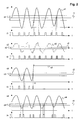
Figur 2 zeigt entlang einer horizontalen Zeitachse t einen Verlauf s1 einer ersten Grösse, einen ersten Referenzwert r1, einen ersten Toleranzbereich dl und ein Verlauf f1 eines ersten Flags, einen Verlauf s2 einer zweiten Grösse, einen zweiten Referenzwert r2, einen zweiten Toleranzbereich d2 und ein zweites Flag f2, einen Verlauf s3 einer dritten Grösse, einen dritten Referenzwert r3, einen dritten Toleranzbereich d3 und ein drittes Flag f3, sowie einen Verlauf s4 einer vierten Grösse, einen vierten Referenzwert r4, einen vierten Toleranzbereich d4 und ein viertes Flag f4. Das erste respektive zweite Flag f1,f2 werden in der oben beschriebenen Weise nur dann auf einen Wert eins gesetzt, wenn sich die erste respektive zweite Grösse sl,s2 innerhalb des ersten respektive zweiten Toleranzbereiches dl,d2 um den ersten respektive zweiten Referenzwert r1,r2 befindet. Das Gleiche gilt analog für das dritte und vierte Flag f3,f4. FIG. 2 shows a curve s1 along a horizontal time axis t first size, a first reference value r1, a first tolerance range dl and a course f1 of a first flag, a course s2 of a second variable, a second reference value r2, a second tolerance range d2 and a second flag f2, a curve s3 of a third variable, a third reference value r3, a third tolerance range d3 and a third flag f3, and a curve s4 of a fourth variable, a fourth reference value r4, one fourth tolerance range d4 and a fourth flag f4. The first or second Flags f1, f2 are then only in the manner described above Set value one if the first or second quantity sl, s2 is within of the first or second tolerance range d1, d2 around the first respectively second reference value r1, r2. The same applies analogously to the third and fourth flags f3, f4.
Die erste Grösse weist einen kontinuierlichen Verlauf s1 ihrer Werte auf, die
zweite Grösse weist diskrete Werte s2 auf. Die erste und zweite Grösse entsprechen
beispielsweise einer Eingangsgrösse 2 respektive einer Ausgangsgrösse
3 eines funktionierenden Analog-Digital-Wandlers 1. Dabei liegt die
Ausgangsgrösse des Wandlers 1 digital codiert vor. In einer anderen Variante
der Erfindung ist der Wandler 1 ein Analogverstärker und entsprechen bei
funktionierendem Wandler 1 die Verläufe der Eingangsgrösse 2 und der Ausgangsgrösse
3 beide annähernd dem Verlauf der ersten Grösse. In einer weiteren
Variante der Erfindung ist der Wandler 1 ein Digital-Analog-Wandler
und entsprechen bei funktionierendem Wandler 1 die Verläufe der Eingangsgrösse
2 und der Ausgangsgrösse 3 beide annähernd dem Verlauf der zweiten
Grösse.The first variable has a continuous course s1 of its values, the
the second size has discrete values s2. The first and second sizes correspond
for example, an
Falls der Wandler 1 nicht funktioniert, indem er die Ausgangsgrösse 3 nach
einem Zeitpunkt t1 dauernd in ein Maximum oder ein Minimum treibt, übersteuert,
so tritt ein Verlauf der Ausgangsgrösse 3 entsprechend dem Verlauf
s3 auf. Der entsprechende Verlauf f3 eines Ausgangsflags 7 zeigt, dass der
Ausgangsdetektor 6 nach dem Zeitpunkt t1 nie anspricht. Somit tritt auch
keine Übereinstimmung von Eingangsflags 5 mit Ausgangsflags 7 auf. Dadurch
wird eine Fehlfunktion des Wandlers 1 detektiert und durch Setzen des
Statussignals 9 übermittelt.If the
Falls der Wandler 1 nicht funktioniert, indem die Ausgangsgrösse 3 einen zu
grossen Offset aufweist, so tritt bei einem Verlauf einer Eingangsgrösse 2
gemäss s1 oder s2 ein Verlauf der Ausgangsgrösse 3 entsprechend dem
Verlauf s4 auf. Der entsprechende Verlauf f4 eines Ausgangsflags 7 zeigt,
dass der Ausgangsdetektor 6 zu anderen Zeitpunkten als ein Eingangsdetektor
4 bei einem Verlauf gemäss s1 anspricht. Somit tritt auch hier keine
Übereinstimmung von Eingangsflags 5 mit Ausgangsflags 7 auf. Dadurch
wird eine Fehlfunktion des Wandlers 1 detektiert und durch Setzen des Statussignals
9 übermittelt.If
Die Referenzwerte 41, 61 werden durch einen Abgleich des Wandlers 1, beispielsweise
bei einer Inbetriebnahme, bestimmt. Falls der Wandler 1 ein
Analog-Digital-Wandler ist, wird der Eingangsgrösse 2 als vorgegebener Wert
bevorzugt ein Wert Null aufgeschaltet, beispielsweise ein Erdpotential oder
ein Strom Null. Als Eingangsreferenzwert 41, bei welchem der Eingangsdetektor
4 anspricht, wird ebenfalls ein Wert Null definiert. Aufgrund eines
Offsets des Wandlers 1 ergibt sich ein bestimmter, Wert der Ausgangsgrösse
3, der im allgemeinen von Null verschieden ist. Dieser Wert der Ausgangsgrösse
3 wird als Ausgangsreferenzwert 61 gewählt, bei welchem der Ausgangsdetektor
6 anspricht. Der Ausgangsreferenzwert 61 entspricht dem
Eingangsreferenzwert 41 Null. Falls der Wandler 1 ein Digital-Analog-Wandler
ist, wird die Eingangsgrösse 2 variiert, bis die Ausgangsgrösse 3 einen Wert
Null aufweist. Der entsprechende Wert der Eingangsgrösse 2 wird als Eingangsreferenzwert
41 gewählt und einem Ausgangsreferenzwert 61 Null zugeordnet.
In ähnlicher Weise geschieht ein Abgleich, welcher anstelle eines
Erdpotentials eine Versorgungsspannung oder eine Nennspannung einer
Anlage als Referenzwert einer Analogseite eines Wandlers 1 verwendet.The reference values 41, 61 are obtained by comparing the
Die erfindungsgemässe Überwachungsvorrichtung 10 zur Funktionsüberwachung eines Wandlers 1, wobei der Wandler 1 ein Analogwandler oder ein bestehender Wandler 1 einer Anlage ist, weist somit
einen Eingangsdetektor 4 zur Erzeugung des Eingangsflags 5 entsprechend einer Detektion des Eingangsreferenzwertes 41der Eingangsgrösse 2 desWandlers 1,einen Ausgangsdetektor dem Ausgangsdetektor des Wandlers 1 sowieeine Auswerteeinheit 8 zum Vergleich der Resultate der Detektoren, also der Ein-und Ausgangsflags Flags
- an
input detector 4 for generating theinput flag 5 in accordance with a detection of theinput reference value 41 of theinput variable 2 of theconverter 1, - an
output detector output flag output reference value output detector output size converter 1 and - an
evaluation unit 8 for comparing the results of the detectors, that is to say the input andoutput flags status signal 9 for transmitting a match between theflags
Figur 3 zeigt eine bevorzugte Variante der Erfindung: Eine Überwachungsvorrichtung
10 weist einen Wandler 1, einen Ausgangsdetektor 6 und eine Digitaleinheit
12 auf. Der Wandler 1 ist ein Digital-Analog-Wandler, der die Eingangsgrösse
2 von der Digitaleinheit 12 in digital codierter Form erhält. Die
Digitaleinheit 12 erhält die Eingangsgrösse 2 über einen nicht gezeigten Eingang
übermittelt, oder erzeugt die Eingangsgrösse 2 selber. Der Ausgangsdetektor
6 ist ein analoger Baustein, welcher das Ausgangsflag 7 oder Analogflag
der Digitaleinheit 12 übermittelt. Das Analogflag zeigt eine Übereinstimmung
der Ausgangsgrösse 3 mit dem Ausgangsreferenzwert 61 an. Die
Digitaleinheit 12 weist eine programmierbare Recheneinheit wie einen Mikroprozessor
oder einen ASIC (Application-Specific Integrated Circuit) oder
FPGA (Field Programmable Gate Array) und/oder eine speziell ausgelegte digitale
Schaltung auf. Die oben beschriebenen Funktionen des Eingangsdetektors
4 und der Auswerteeinheit 8 sind in der Digitaleinheit 12 realisiert. Dazu
bildet sie ein vorzugsweise ein Digitalflag, welches eine Übereinstimmung
der Eingangsgrösse 2 mit dem Eingangsreferenzwert 41 anzeigt. Das Digitalflag
wird vorzugsweise durch eine interne Variable oder ein internes Signal
der Digitaleinheit 12 realisiert.FIG. 3 shows a preferred variant of the invention: a monitoring
Figur 4 zeigt eine weitere bevorzugte Variante der Erfindung. Eine Überwachungsvorrichtung
10 weist einen Wandler 1, einen Eingangsdetektor 4 und
eine Digitaleinheit 12 auf. Der Wandler 1 ist ein Analog-Digital-Wandler, der
die Ausgangsgrösse 3 in digital codierter Form an eine Digitaleinheit 12
übermittelt. Die Digitaleinheit 12 übermittelt die Ausgangsgrösse 3 über einen
nicht gezeigten Ausgang und/oder verarbeitet sie selber. Der Eingangsdetektor
4 ist ein analoger Baustein, welcher das Eingangsflag 5 oder Analogflag
der Digitaleinheit 12 übermittelt. Das Analogflag zeigt eine Übereinstimmung
der Eingangsgrösse 2 mit dem Eingangsreferenzwert 41 an. Die
Digitaleinheit 12 weist eine programmierbare Recheneinheit wie einen Mikroprozessor
oder einen ASIC oder FPGA und/oder eine speziell ausgelegte
digitale Schaltung auf. Die oben beschriebenen Funktionen des Ausgangsdetektors
6 und der Auswerteeinheit 8 sind in der Digitaleinheit 12 realisiert.
Dazu bildet sie ein Digitalflag, welches eine Übereinstimmung der Ausgangsgrösse
3 mit dem Ausgangsreferenzwert 61 anzeigt. Das Digitalflag
wird vorzugsweise durch eine interne Variable oder ein internes Signal der
Digitaleinheit 12 realisiert.FIG. 4 shows a further preferred variant of the invention. A
Figur 5 zeigt eine weitere bevorzugte Variante der Erfindung. Darin besteht
der Wandler 1 aus mehreren kaskadierten Teilwandlern 1',1",1"', deren Ausgangsgrössen
3',3",3"' auf Ausgangsdetektoren 6',6",6"' zur Bildung von
Ausgangsflags 7',7",7"' geführt werden. Das Eingangsflag 5 und die Ausgangsflags
7',7",7"'werden durch die Auswerteeinheit 8 ausgewertet, welche
bei einer fehlenden Übereinstimmung des Eingangsflags 5 und/oder der
Ausgangsflags 7',7",7"' auf eine Fehlfunktion eines Teilwandlers 1',1",1"'
schliesst.FIG. 5 shows a further preferred variant of the invention. That is
the
In einer bevorzugten Variante der Erfindung entsprechen die vorgegebenen Referenzwerte einem Wert Null eines Stromes, oder einem Wert Null einer Spannung, also einem Erdpotential, und/oder einer Versorgungsspannung einer elektrischen Anlage. Solche Referenzwerte haben den Vorteil, dass sie überall in einer Anlage auftreten und definiert sind. Falls ein Referenzwert einer analogen Grösse einem Erdpotential oder einem Wert Null entspricht, so ist der analoge Detektor einfach ein analoger Komparator, dessen Umschaltschwelle gleich einer oberen Grenze des vorgegebenen Toleranzbereiches um den Referenzwert Null ist. Unterschreitet ein Absolutwert der analogen Grösse die obere Grenze des Toleranzbereiches, so setzt der Komparator sein Ausgangssignal oder Analogflag auf den Wert eins und zeigt damit an, dass die analoge Grösse den vorgegebenen Referenzwert Null aufweist.In a preferred variant of the invention, the given ones correspond Reference values a zero value of a current, or a zero value of a Voltage, i.e. a ground potential, and / or a supply voltage an electrical system. Such reference values have the advantage that they occur anywhere in a system and are defined. If a reference value an analog quantity corresponds to an earth potential or a value of zero, so the analog detector is simply an analog comparator whose switchover threshold equal to an upper limit of the specified tolerance range around the reference value is zero. Falls below an absolute value of the analog The comparator sets the size of the upper limit of the tolerance range its output signal or analog flag to the value one and thus shows indicates that the analog quantity has the specified reference value zero.
Das erfindungsgemässe Verfahren eignet sich insbesondere zur Funktionsüberwachung
eines Wandlers einer Steuer- oder Schutzeinrichtung einer
elektrischen Schaltanlage. Beispielsweise werden Digital-Analog-Wandler 1
eingesetzt, um digital über Glasfasern übertragene Signale 2 von Schutzgeräten
in Analogsignale 3 umzusetzen. Diese Analogsignale 3 werden auf
Analogeingänge von bestehenden älteren Schutzgeräten geführt. Vorzugsweise
wird eine erfindungsgemässe Überwachungsvorrichtung 10 gemäss
der Struktur von Figur 3 für einen solchen Digital-Analog-Wandler 1 eingesetzt.
Vorzugsweise werden damit Spannungen anhand von Referenzwerten
Null, welche Erdpotential entsprechen, überwacht. Auch Ströme werden vorzugsweise
anhand von Referenzwerten Null überwacht. Für einen Abgleich
einer Überwachung eines Wandlers 1, welcher eine Strommessung verarbeitet,
wird ein entsprechender Leitungsabschnitt stromlos geschaltet.The method according to the invention is particularly suitable for function monitoring
a converter of a control or protective device
electrical switchgear. For example, digital-to-
Eine Fehlfunktion eines Wandlers 1, der zu einer Übersteuerung der Ausgangsgrösse
3 des Wandlers 1 führt, lässt sich im Falle eines Wandlers 1,
welcher eine Strommessung verarbeitet, nicht kurzfristig, das heisst, in einer
Zeit während der eine Schutzeinrichtung reagieren muss, von einem Kurzschlusstrom
in der Anlage unterscheiden. Hier erlaubt die Erfindung, die
Fehlfunktion zu detektieren.A malfunction of a
Bei einer Funktionsüberwachung eines Wandlers 1 einer Schutzeinrichtung
einer elektrischen Schaltanlage wird vorzugsweise bei einer Detektion einer
Fehlfunktion des Wandlers 1 die Ausgangsgrösse 3 als ungültig markiert,
beispielsweise durch Übermittlung eines entsprechenden Statussignals. Vorzugsweise
werden in diesem Fall Schutzfunktionen, welche auf den Wandler
1 angewiesen sind, ausgeschaltet. Dies ist zulässig, weil Störfälle in Schaltanlagen
sehr selten auftreten. Vorteilhafterweise ist dabei das Risiko einer
Betriebsstörung durch einen defekten Wandler 1 grösser ist als das Risiko
eines nicht optimal erfassten Störfalls.When monitoring the function of a
Die Erfindung hat den Vorteil, dass eine Überwachung mit sehr einfachen
Mitteln realisierbar ist. Beispielsweise wird für einen Digital-Analog-Wandler
oder einen Analog-Digital-Wandler nur ein zusätzlicher analoger Baustein
benötigt, währenddem die übrigen Funktionen in einer ohnehin vorhandenen,
beispielsweise programmierbaren, Digitaleinheit 12 realisiert werden.
Auch ist eine erfindungsgemässe Überwachung nachträglich bei einem bestehenden
Wandler implementierbar.The invention has the advantage that monitoring is very simple
Means is feasible. For example, for a digital-to-analog converter
or an analog-to-digital converter just an additional analog component
needed, while the other functions in an already existing,
for example programmable,
- 11
- WandlerConverter
- 1',1",1"'1 ', 1 ", 1"'
- TeilwandlerPartial converter
- 22nd
- EingangsgrösseInput size
- 3,3',3",3"'3.3 ', 3 ", 3"'
- AusgangsgrösseInitial size
- 44th
- EingangsdetektorInput detector
- 55
- EingangsflagEntry flag
- 6,6',6",6"'6.6 ', 6 ", 6"'
- AusgangsdetektorOutput detector
- 7,7',7",7"'7.7 ', 7 ", 7"'
- AusgangsflagExit flag
- 88th
- AuswerteeinheitEvaluation unit
- 99
- StatussignalStatus signal
- 1010th
- ÜberwachungsvorrichtungMonitoring device
- 1212th
- DigitaleinheitDigital unit
- 4141
- EingangsreferenzwertInput reference value
- 61,61',61",61"'61.61 ', 61 ", 61"'
- AusgangsreferenzwertOutput reference value
- s1,s2,s3,s4s1, s2, s3, s4
- erster, zweiter, dritter und vierter Verlauffirst, second, third and fourth course
- r1,r2,r3,r4r1, r2, r3, r4
- erster, zweiter. dritter und vierter Referenzwertfirst, second. third and fourth reference value
- d1,d2,d3,d4d1, d2, d3, d4
- erster, zweiter, dritter und vierter Toleranzbereichfirst, second, third and fourth tolerance range
- f1 ,f2,f3,f4f1, f2, f3, f4
- erstes, zweites, drittes und viertes Flagfirst, second, third and fourth flags
Claims (10)
Priority Applications (4)
| Application Number | Priority Date | Filing Date | Title |
|---|---|---|---|
| EP99811073A EP1102403A1 (en) | 1999-11-19 | 1999-11-19 | Operation monitoring for a transformer |
| JP2000350603A JP5068899B2 (en) | 1999-11-19 | 2000-11-17 | Apparatus and method for monitoring converter operation |
| US09/715,019 US6577987B1 (en) | 1999-11-19 | 2000-11-20 | Operational monitoring for a converter |
| US11/150,597 USRE41343E1 (en) | 1999-11-19 | 2005-06-10 | Operational monitoring for a converter |
Applications Claiming Priority (1)
| Application Number | Priority Date | Filing Date | Title |
|---|---|---|---|
| EP99811073A EP1102403A1 (en) | 1999-11-19 | 1999-11-19 | Operation monitoring for a transformer |
Publications (1)
| Publication Number | Publication Date |
|---|---|
| EP1102403A1 true EP1102403A1 (en) | 2001-05-23 |
Family
ID=8243154
Family Applications (1)
| Application Number | Title | Priority Date | Filing Date |
|---|---|---|---|
| EP99811073A Withdrawn EP1102403A1 (en) | 1999-11-19 | 1999-11-19 | Operation monitoring for a transformer |
Country Status (3)
| Country | Link |
|---|---|
| US (2) | US6577987B1 (en) |
| EP (1) | EP1102403A1 (en) |
| JP (1) | JP5068899B2 (en) |
Families Citing this family (3)
| Publication number | Priority date | Publication date | Assignee | Title |
|---|---|---|---|---|
| AU2007216691A1 (en) * | 2006-09-11 | 2008-04-03 | Universidad Tecnica Federico Santa Maria | Intelligent monitoring system and method for mill drives in mineral grinding processes |
| JP6318483B2 (en) * | 2013-06-28 | 2018-05-09 | 株式会社デンソー | Electronic device manufacturing method and limit value setting device |
| US9634624B2 (en) | 2014-12-24 | 2017-04-25 | Stmicroelectronics S.R.L. | Method of operating digital-to-analog processing chains, corresponding device, apparatus and computer program product |
Citations (2)
| Publication number | Priority date | Publication date | Assignee | Title |
|---|---|---|---|---|
| DD251659A1 (en) * | 1986-07-29 | 1987-11-18 | Zeiss Jena Veb Carl | CIRCUIT ARRANGEMENT FOR CHECKING AND ADJUSTING ANALOG DIGITAL CONVERTERS |
| EP0883249A2 (en) * | 1997-06-03 | 1998-12-09 | Leine & Linde AB | Encoder |
Family Cites Families (15)
| Publication number | Priority date | Publication date | Assignee | Title |
|---|---|---|---|---|
| DE251659C (en) | ||||
| US3816813A (en) * | 1972-01-24 | 1974-06-11 | Spacetac Inc | Automatic converter tester |
| US4215412A (en) | 1978-07-13 | 1980-07-29 | The Boeing Company | Real time performance monitoring of gas turbine engines |
| US4266292A (en) * | 1978-11-20 | 1981-05-05 | Wescom Switching, Inc. | Method and apparatus for testing analog-to-digital and digital-to-analog code converters |
| US4419656A (en) * | 1980-11-07 | 1983-12-06 | Fairchild Camera & Instrument Corp. | Method and apparatus for digital converter testing |
| DE3614597A1 (en) * | 1986-04-30 | 1987-11-05 | Bosch Gmbh Robert | METHOD AND CIRCUIT FOR THE A / D CONVERSION OF A DC VOLTAGE SIGNAL |
| JPS6489820A (en) * | 1987-09-30 | 1989-04-05 | Kawasaki Steel Co | Fault detection method in a/d converter and d/a converter |
| JPH0389717A (en) * | 1989-09-01 | 1991-04-15 | Nec Corp | Fault detection circuit |
| EP0447117B1 (en) * | 1990-03-15 | 1997-02-19 | AT&T Corp. | Built-in self test for analog to digital converters |
| US5185607A (en) * | 1992-01-31 | 1993-02-09 | Motorola, Inc. | Method and apparatus for testing an analog to digital converter |
| US5319370A (en) * | 1992-08-31 | 1994-06-07 | Crystal Semiconductor, Inc. | Analog-to-digital converter with a continuously calibrated voltage reference |
| US5321403A (en) * | 1993-04-14 | 1994-06-14 | John Fluke Mfg. Co., Inc. | Multiple slope analog-to-digital converter |
| DE19810469A1 (en) * | 1998-03-11 | 1999-09-16 | Philips Patentverwaltung | Circuit arrangement for controlling an output load |
| JP3819589B2 (en) * | 1998-04-30 | 2006-09-13 | 株式会社アドバンテスト | AD converter evaluation device |
| US6297757B1 (en) * | 1999-02-11 | 2001-10-02 | Motorola, Inc. | Method and circuit for testing an analog-to-digital converter module on a data processing system having an intermodule bus |
-
1999
- 1999-11-19 EP EP99811073A patent/EP1102403A1/en not_active Withdrawn
-
2000
- 2000-11-17 JP JP2000350603A patent/JP5068899B2/en not_active Expired - Fee Related
- 2000-11-20 US US09/715,019 patent/US6577987B1/en not_active Ceased
-
2005
- 2005-06-10 US US11/150,597 patent/USRE41343E1/en not_active Expired - Lifetime
Patent Citations (2)
| Publication number | Priority date | Publication date | Assignee | Title |
|---|---|---|---|---|
| DD251659A1 (en) * | 1986-07-29 | 1987-11-18 | Zeiss Jena Veb Carl | CIRCUIT ARRANGEMENT FOR CHECKING AND ADJUSTING ANALOG DIGITAL CONVERTERS |
| EP0883249A2 (en) * | 1997-06-03 | 1998-12-09 | Leine & Linde AB | Encoder |
Also Published As
| Publication number | Publication date |
|---|---|
| JP2001211074A (en) | 2001-08-03 |
| USRE41343E1 (en) | 2010-05-18 |
| JP5068899B2 (en) | 2012-11-07 |
| US6577987B1 (en) | 2003-06-10 |
Similar Documents
| Publication | Publication Date | Title |
|---|---|---|
| DE3923432C2 (en) | Device for generating measurement signals with a plurality of sensors | |
| EP0402508A1 (en) | Process and means for detecting a series of abnormal events in an electrical signal, especially the depolarisation signal of a heart | |
| DE3924988C2 (en) | Circuit arrangement for controlling the safety relay of an electronically controlled brake system of a motor vehicle | |
| DE4039521C2 (en) | Speed gap error detector for rail vehicles | |
| DE3347459C2 (en) | ||
| DE1952349B2 (en) | ARRANGEMENT FOR TESTING A REDUNDANT CONTROL SYSTEM | |
| EP0610711B1 (en) | Electronic device for the control of an electrical motor device, in particular a device for a garage door | |
| DE4242177A1 (en) | Circuit arrangement for monitoring a large number of coils | |
| EP0688078A2 (en) | Busbar protection method and device | |
| EP3935703A1 (en) | Locating an earth fault in a dc network | |
| EP0524330B1 (en) | Process for fault recognition and location in redundant signal generating devices used in a automation system | |
| WO1988005570A1 (en) | Process and device for monitoring computer-controlled final control elements | |
| WO2001069272A2 (en) | Device and method for monitoring a capacitor bushing | |
| DE102012014493B4 (en) | Method and device for the redundant detection of a direction of rotation | |
| EP1102403A1 (en) | Operation monitoring for a transformer | |
| EP2169645B1 (en) | Test of reporting lines on a danger reporting assembly | |
| EP0170138A1 (en) | Protective device for an electrical-power system | |
| DE10037432A1 (en) | Monitoring of a capacitor bushing to detect faults, by comparison of the quotient of electrical measurements with a characterizing value, with any deviation indicating a fault, the invention being independent of operating voltage | |
| DE4403156B4 (en) | Method and device for carrying out the method for controlling a consumer | |
| WO2001088560A1 (en) | Arrangement for detecting malfunction | |
| EP2169644A1 (en) | Test of reporting lines on a danger reporting assembly | |
| DE4313532A1 (en) | Method for testing an output stage | |
| EP0927356B1 (en) | Method of checking electrical components and device for carrying out this method | |
| DE102012202642A1 (en) | Electric switch | |
| DE102020210339B4 (en) | Circuit arrangement and method for error detection |
Legal Events
| Date | Code | Title | Description |
|---|---|---|---|
| PUAI | Public reference made under article 153(3) epc to a published international application that has entered the european phase |
Free format text: ORIGINAL CODE: 0009012 |
|
| AK | Designated contracting states |
Kind code of ref document: A1 Designated state(s): AT BE CH CY DE DK ES FI FR GB GR IE IT LI LU MC NL PT SE |
|
| AX | Request for extension of the european patent |
Free format text: AL;LT;LV;MK;RO;SI |
|
| 17P | Request for examination filed |
Effective date: 20011005 |
|
| AKX | Designation fees paid |
Free format text: AT BE CH CY DE DK ES FI FR GB GR IE IT LI LU MC NL PT SE |
|
| RAP1 | Party data changed (applicant data changed or rights of an application transferred) |
Owner name: ABB SCHWEIZ AG |
|
| 17Q | First examination report despatched |
Effective date: 20040524 |
|
| STAA | Information on the status of an ep patent application or granted ep patent |
Free format text: STATUS: THE APPLICATION IS DEEMED TO BE WITHDRAWN |
|
| 18D | Application deemed to be withdrawn |
Effective date: 20040602 |