EP1102306A1 - Discharge lamp - Google Patents
Discharge lamp Download PDFInfo
- Publication number
- EP1102306A1 EP1102306A1 EP00124933A EP00124933A EP1102306A1 EP 1102306 A1 EP1102306 A1 EP 1102306A1 EP 00124933 A EP00124933 A EP 00124933A EP 00124933 A EP00124933 A EP 00124933A EP 1102306 A1 EP1102306 A1 EP 1102306A1
- Authority
- EP
- European Patent Office
- Prior art keywords
- light
- outer tube
- intercepting
- discharge lamp
- arc tube
- Prior art date
- Legal status (The legal status is an assumption and is not a legal conclusion. Google has not performed a legal analysis and makes no representation as to the accuracy of the status listed.)
- Granted
Links
- 239000000463 material Substances 0.000 claims description 9
- 229910010272 inorganic material Inorganic materials 0.000 claims description 5
- 239000011147 inorganic material Substances 0.000 claims description 5
- 239000011159 matrix material Substances 0.000 claims description 5
- 238000001354 calcination Methods 0.000 claims description 4
- 230000004313 glare Effects 0.000 abstract description 27
- 239000011521 glass Substances 0.000 description 16
- 238000007789 sealing Methods 0.000 description 10
- 229910001507 metal halide Inorganic materials 0.000 description 7
- 150000005309 metal halides Chemical class 0.000 description 7
- WABPQHHGFIMREM-UHFFFAOYSA-N lead(0) Chemical compound [Pb] WABPQHHGFIMREM-UHFFFAOYSA-N 0.000 description 5
- 229910052751 metal Inorganic materials 0.000 description 3
- 239000002184 metal Substances 0.000 description 3
- 239000011888 foil Substances 0.000 description 2
- 238000000059 patterning Methods 0.000 description 2
- 239000004697 Polyetherimide Substances 0.000 description 1
- 229910018094 ScI3 Inorganic materials 0.000 description 1
- 239000000919 ceramic Substances 0.000 description 1
- 230000000694 effects Effects 0.000 description 1
- 239000004973 liquid crystal related substance Substances 0.000 description 1
- QSHDDOUJBYECFT-UHFFFAOYSA-N mercury Chemical compound [Hg] QSHDDOUJBYECFT-UHFFFAOYSA-N 0.000 description 1
- 229910052753 mercury Inorganic materials 0.000 description 1
- 229910052756 noble gas Inorganic materials 0.000 description 1
- 229920001601 polyetherimide Polymers 0.000 description 1
- 239000002243 precursor Substances 0.000 description 1
- 239000011347 resin Substances 0.000 description 1
- 229920005989 resin Polymers 0.000 description 1
- FVAUCKIRQBBSSJ-UHFFFAOYSA-M sodium iodide Inorganic materials [Na+].[I-] FVAUCKIRQBBSSJ-UHFFFAOYSA-M 0.000 description 1
- 229910052724 xenon Inorganic materials 0.000 description 1
- FHNFHKCVQCLJFQ-UHFFFAOYSA-N xenon atom Chemical compound [Xe] FHNFHKCVQCLJFQ-UHFFFAOYSA-N 0.000 description 1
Images





Classifications
-
- H—ELECTRICITY
- H01—ELECTRIC ELEMENTS
- H01J—ELECTRIC DISCHARGE TUBES OR DISCHARGE LAMPS
- H01J61/00—Gas-discharge or vapour-discharge lamps
- H01J61/02—Details
- H01J61/30—Vessels; Containers
- H01J61/35—Vessels; Containers provided with coatings on the walls thereof; Selection of materials for the coatings
-
- F—MECHANICAL ENGINEERING; LIGHTING; HEATING; WEAPONS; BLASTING
- F21—LIGHTING
- F21S—NON-PORTABLE LIGHTING DEVICES; SYSTEMS THEREOF; VEHICLE LIGHTING DEVICES SPECIALLY ADAPTED FOR VEHICLE EXTERIORS
- F21S41/00—Illuminating devices specially adapted for vehicle exteriors, e.g. headlamps
- F21S41/10—Illuminating devices specially adapted for vehicle exteriors, e.g. headlamps characterised by the light source
- F21S41/14—Illuminating devices specially adapted for vehicle exteriors, e.g. headlamps characterised by the light source characterised by the type of light source
- F21S41/17—Discharge light sources
- F21S41/172—High-intensity discharge light sources
-
- F—MECHANICAL ENGINEERING; LIGHTING; HEATING; WEAPONS; BLASTING
- F21—LIGHTING
- F21S—NON-PORTABLE LIGHTING DEVICES; SYSTEMS THEREOF; VEHICLE LIGHTING DEVICES SPECIALLY ADAPTED FOR VEHICLE EXTERIORS
- F21S41/00—Illuminating devices specially adapted for vehicle exteriors, e.g. headlamps
- F21S41/40—Illuminating devices specially adapted for vehicle exteriors, e.g. headlamps characterised by screens, non-reflecting members, light-shielding members or fixed shades
- F21S41/43—Illuminating devices specially adapted for vehicle exteriors, e.g. headlamps characterised by screens, non-reflecting members, light-shielding members or fixed shades characterised by the shape thereof
-
- H—ELECTRICITY
- H01—ELECTRIC ELEMENTS
- H01J—ELECTRIC DISCHARGE TUBES OR DISCHARGE LAMPS
- H01J61/00—Gas-discharge or vapour-discharge lamps
- H01J61/02—Details
- H01J61/04—Electrodes; Screens; Shields
-
- H—ELECTRICITY
- H01—ELECTRIC ELEMENTS
- H01J—ELECTRIC DISCHARGE TUBES OR DISCHARGE LAMPS
- H01J61/00—Gas-discharge or vapour-discharge lamps
- H01J61/02—Details
- H01J61/025—Associated optical elements
Definitions
- the present invention relates to a discharge lamp for a headlight, more particularly to the shapes of light-intercepting films included in a lamp.
- a discharge lamp When a discharge lamp is used as a light source for a vehicle headlight or for a liquid crystal projector, it is combined with a reflecting mirror.
- a discharge lamp including ultraviolet-cutting glass as an outer tube has been used widely.
- JP-9-500489A proposes a discharge lamp including an arc tube enclosed by an outer tube.
- external lead wires extend from respective electrodes to respective contact points to a base.
- a neck portion of the arc tube is fixed into the base, and a power supply line for one external lead wire extends along the external surface of the outer tube.
- a light-intercepting film extends on the side close to the base, from the position making an angle ⁇ of 50 degrees with a line perpendicular to the outer tube at the center region between the electrodes, to the position making an angle ⁇ of 65 degrees with the same line.
- two band-shaped light-intercepting films extend in parallel with the outer tube, and the two band-shaped light-intercepting films face apart from each other.
- the two band-shaped light-intercepting films have respective edges making an angle ⁇ of 165 degrees with respect to the circumference of the outer tube, and respective edges facing with each other and making an angle ⁇ of between 85 degrees and 145 degrees.
- FIG. 11A illustrates a configuration of a headlight using the conventional discharge lamp.
- a discharge lamp 40 includes an arc tube 42 enclosed by an outer tube 41, and is arranged within a mirror 45 having a front glass 44 mounted at its opening.
- a light-intercepting film 46a extends on the side close to a base 43 of the outer tube 41, and two band-shaped light-intercepting films 46b (only a film on one side is shown) extend in parallel with the axial direction of the outer tube 41.
- FIG. 11B shows a light distribution pattern.
- a region 48 is a region illuminated by light passing through the front glass 44.
- a region 50 indicated by a dot pattern shows a region where light passing through the front glass 44 does not reach.
- the boundary between the regions 48 and 50 is a cutline 49.
- unwanted light is cut from light radiated from the arc tube 42 by the light-intercepting films 46a and 46b and a light-intercepting plate 47.
- the illuminated region indicated by 48a in Fig. 11B is wider than the illuminated region indicated by 48b.
- a discharge lamp forming such a light distribution pattern is used for a vehicle, both sides of driving lane and opposing lane can be illuminated.
- the region 48b on the side of opposing lane is cut for its upper illuminated region compared to the region 48a on the side of driving lane, blinding of oncoming vehicles can be prevented.
- unwanted light (arrows "b” and “c") radiated from the arc tube 42 and reflected by the end on the side far from the base 43 (particularly, at the corners of the end of the outer tube 41) is reflected by the mirror 45, and passes through the front glass 44 to illuminate forward.
- Such light is unwanted to form the light distribution pattern as shown in Fig. 11B, and it will illuminate the region 50 that does not need to be illuminated, or will illuminate the region 48 that has been illuminated by the necessary light indicated by the arrows "a” over again.
- unevenness is generated in the intensity distribution of the light distribution pattern, resulting in the generation of glare.
- the present invention solves the above-mentioned conventional problem. It is an object of the present invention to provide a discharge lamp further including a light-intercepting film extending in a portion far from the base, so that glare can be reduced, and a lighting fixture can be simplified and reduced in weight.
- the present invention provides a first discharge lamp including: an arc tube having a discharge space in which a pair of electrodes having tips facing with each other are arranged; an outer tube enclosing the arc tube; a base that fixes one side of the outer tube; and two band-shaped light-intercepting films extending on a surface of the outer tube in the direction of the axis of the arc tube and in parallel with each other, the two band-shaped light-intercepting films having at least a portion overlapping both ends of the discharge space when viewing the outer tube in the direction perpendicular to the axis of the arc tube, wherein: when the tip within the discharge space of the electrode on the side of the top of the outer tube between the pair of the electrodes is determined as a basis position, in at least one of the two band-shaped light-intercepting films, an extending portion is formed that is on the side of the top of the outer tube with respect to the basis position and extends in the circumferential direction of the outer tube.
- reflected light from the end of the outer tube on the side far from the base can be cut, and unwanted light can be cut more reliably.
- unevenness in the intensity distribution of the light distribution pattern can be reduced, and generation of glare can be prevented.
- glare can be reduced by the lamp itself, it is not necessary to intercept unwanted light by providing a light-intercepting plate separately, and it is not necessary to add a further mechanism for reducing glare such as a light-intercepting plate, so that a lighting fixture can be simplified and reduced in weight.
- a power supply line further is arranged so as to face the side face of the outer tube, and the extending portion is formed so as to extend toward the side opposite to the side on which the power supply line and the outer tube face each other.
- the angle, taken with respect to the side opposite the extending portion, between the two lines connecting the center point and respective edges of the two light-intercepting films in the direction of the axis of the arc tube on the side of the extending portion is determined as an angle ⁇
- the angle, taken with respect to the side opposite the extending portion between the two lines connecting the point on the axis of the arc tube and respective edges of the two light-intercepting films in the direction of the axis of the arc tube on the side of the extending portion is determined as an angle ⁇
- the maximum value of the angle E is at least ( ⁇ + 10) degrees.
- the light-intercepting films are formed by uniting a heat-resistant light-intercepting sheet material with the surface of the outer tube. According to such a discharge lamp, the precision of the location of the light-intercepting films can be enhanced.
- the heat-resistant light-intercepting sheet material is a greensheet containing an inorganic material and an inorganic matrix component, and the greensheet is united with the surface of the outer tube by calcining the greensheet adhered on the surface of the outer tube.
- the present invention provides a second discharge lamp including: an arc tube having a discharge space in which a pair of electrodes having tips facing with each other are arranged; an outer tube enclosing the arc tube; a base that fixes one side of the outer tube; and first two band-shaped light-intercepting films extending on a surface of the outer tube in the direction of the axis of the arc tube and in parallel with each other, the first light-intercepting films having at least a portion overlapping both ends of the discharge space when viewing the outer tube in the direction perpendicular to the axis of the arc tube, further including a second light-intercepting film covering the outer tube in the circumferential direction, wherein when the tip within the discharge space of the electrode on the side of the top of the outer tube between the pair of the electrodes is determined as a basis position, both edges of the second light-intercepting film in the direction of the axis of the arc tube are located on the side of the top of the outer tube with respect to the basis position.
- reflected light from the end of the outer tube on the side far from the base can be cut, and unwanted light can be cut more reliably.
- unevenness in the intensity distribution of the light distribution pattern can be reduced, and generation of glare can be prevented.
- glare can be reduced by the lamp itself, it is not necessary to intercept unwanted light by providing a light-intercepting plate separately, and it is not necessary to add a further mechanism for reducing glare such as a light-intercepting plate, so that a lighting fixture can be simplified and reduced in weight.
- the angle made by the line passing through the center point between the tips of the pair of the electrodes and perpendicular to the axis of the arc tube and the line connecting the center point and the edge of the second light-intercepting film closer to the center point is at least 40 degrees.
- the angle made by the line perpendicular to the axis of the arc tube and the line connecting the center point and the edge of the second light-intercepting film farther from the center point is at least 70 degrees.
- the second light-intercepting film covers the outer tube in a ring form.
- the edge of the second light-intercepting film farther from the center point between the tips of the pair of the electrodes is located at the top of the outer tube, and the second light-intercepting film covers the outer tube in the circumferential direction and covers the top of the outer tube. According to such a discharge lamp, light trying to pass through the top or the vicinity of the top of the outer tube can be cut. Thus, it is not necessary to set a cap for intercepting light at an end of the discharge lamp or to provide a light-intercepting plate separately in front of the discharge lamp so as to cut such light.
- the light-intercepting films are formed by uniting a heat-resistant light-intercepting sheet material with the surface of the outer tube. According to such a discharge lamp, precision of the location of the light-intercepting films can be enhanced.
- the heat-resistant light-intercepting sheet material is a greensheet containing an inorganic material and an inorganic matrix component, and the greensheet is united with the surface of the outer tube by calcining the greensheet adhered on the surface of the outer tube.
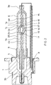
- Fig. 1 is a side view of a discharge lamp according to the first embodiment of the present invention.
- the discharge lamp shown in this drawing is an embodiment of a metal halide lamp for a vehicle headlight.
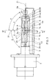
- Fig. 2 is a sectional view of the discharge lamp illustrated in Fig. 1, which is cut in a plane including an axis 21 in the longitudinal direction.
- the discharge lamp of this embodiment has an arc tube 1 within an outer tube 6, and the arc tube 1 includes a luminous portion 1c and a pair of compressed sealing portions 1a and 1b connected to both ends of the luminous portion 1c.
- a discharge space 1d is formed within the luminous portion 1c, and within the discharge space 1d, mercury, ScI 3 and NaI as metal halides, and xenon as a starting noble gas are enclosed.
- main structures of the arc tube 1 within the transparent outer tube 6 are shown by solid lines (this is also the same for Figs. 5 and 7),
- Both ends of the luminous portion lc are sealed with the sealing portions 1a and 1b so that tips of electrodes 2a and 2b are located within the discharge space 1d.
- the sealing portion 1a one end of the electrode 2a and one end of an external lead wire 3a are connected with a metal foil 4a.
- the sealing portion 1b one end of the electrode 2b and one end of an external lead wire 3b are connected with a metal foil 4b.
- the external lead wire 3a leading from the sealing portion la extends from a base 7 and is connected to a power supply line 13 arranged at a side of the outer tube 6. Furthermore, a tubular cylindrical portion 5 is connected to the sealing portion 1b, and the external lead wire 3b leads through inside the cylindrical portion 5.
- Both ends of the outer tube 6 enclosing the arc tube 1 are sealed with the sealing portion la and the cylindrical portion 5, respectively.
- the cylindrical portion 5 of the arc tube 1 is inserted into a cavity 8 formed in a center region of the base 7.
- the base 7 is composed of a resin, such as polyetherimide, etc.
- a support 9 composed of a metal is attached to the base 7, and the outer tube 6 is fitted into the support 9 to be supported in the base 7.
- light-intercepting films formed on the outer tube 6 will be described.
- two band-shaped light-intercepting films 14 and 15 are formed on the external surface of the outer tube 6.
- the light-intercepting film 14 is formed on the front side of the arc tube 1, and its outline is shown by a solid line.
- the light-intercepting film 15 is formed on the back side of the arc tube 1, and its outline is shown by a broken line.
- the light-intercepting films 14 and 15 are formed so as to overlap the discharge space 1d when viewed from the direction perpendicular to the axis 21 of the arc tube 1, in other words, from the side of the side face of the outer tube 6.
- the light-intercepting films 14 and 15 when viewing the light-intercepting films 14 and 15 in the direction perpendicular to the axis 21 of the arc tube 1, include portions overlapping both ends 1e and 1f of the discharge space 1d in the direction of the axis 21.
- the light-intercepting films 14 and 15 are respectively parallel to the axis 21 of the arc tube and apart from each other.
- the light-intercepting films 14 and 15 are formed by uniting a heat-resistant light-intercepting sheet material with a surface of the outer tube 6, and patterning it in a predetermined shape. Accordingly, the precision of the location of the light-intercepting films can be enhanced.
- the heat-resistant light-intercepting sheet material for example, a greensheet containing an inorganic material and an inorganic matrix component is used.
- the greensheet is a precursor material sheet, which is used when obtaining a sintered body using an inorganic material such as ceramics or glass as a matrix component.
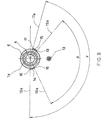
- Fig. 3 is a sectional view taken along the line I-I of Fig. 1 passing through the point A.
- the point A is, specifically, the center point of the line connecting the tips of the electrodes 2a and 2b facing with each other within the discharge space 1d.
- an angle y is the angle, taken with respect to the side of lower edges 18 and 19 of respective light-intercepting films (i.e. on the side of the power supply line 13), between a line 16a passing through the point A and contacting an upper edge 16 of the light-intercepting film 14, and a line 17a passing through the point A and contacting an upper edge 17 of the light-intercepting film 15.
- An angle ⁇ is the angle, taken with respect to the side of lower edges 18 and 19 of respective light-intercepting films (i.e. on the side of the power supply line 13), between a line 18a passing through the point A and contacting the lower edge 18 of the light-intercepting film 14, and a line 19a passing through the point A and contacting the lower edge 19 of the light-intercepting film 15.
- the angle y is 165 degrees
- the angle ⁇ is 125 degrees.
- Fig. 4 is a sectional view taken along the line II-II of Fig. 1. That is, Fig. 4 is a cross section at a position in the region in which the extending portion 15a is formed, and a point B is the point on the axis 21 of the arc tube in this cross section. At this position, an angle ⁇ shows the maximum value, which is 180 degrees in this embodiment.
- the angle ⁇ is, specifically, the angle, taken with respect to the side of the lower edges 18 and 19 of respective light-intercepting films (i.e.
- the angle ⁇ is common, and the angle ⁇ (180 degrees) is greater by 15 degrees than the angle ⁇ (165 degrees). That is, at the position shown in Fig. 4, at least one of the light-intercepting films 14 and 15 extends in the circumferential direction of the outer tube 6 toward the side opposite to the power supply line 13. This extending portion corresponds to the portion indicated by 15a in Fig. 1. When the positions of the line 16a of Fig. 3 and the line 23a of Fig. 4 in the circumferential direction of the outer tube 6 are the same, the extending portion is formed only in the light-intercepting film 15.
- a light-intercepting film 20 is formed on the external surface of the outer tube 6 within a region not facing the power supply line 13 and corresponding to the sealing portion 1b on the side of the base 7. As shown in Fig. 1, the light-intercepting film 20 extends on the external surface of the outer tube 6 on the side not facing the power supply line 13 from the position making an angle ⁇ of 45 degrees with a line 31 perpendicular to the axis 21 of the arc tube to the position making an angle ⁇ of at least 70 degrees with the line 31 when using the point A as the apex.
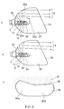
- Fig. 10 illustrates a development of the light-intercepting films shown in Fig. 1. According to this drawing, it is understood that the extending portion 15a is formed in the light-intercepting film 15, one of the two band-shaped light-intercepting films 14 and 15.
- Fig. 9A shows a configuration of a headlight using the discharge lamp of this embodiment.
- the discharge lamp is arranged within a mirror 33 having a front glass 34 mounted at its opening.
- Fig. 9C shows a light distribution pattern.
- a region 36 is the region illuminated by the light passing through the front glass 34.
- a region 37 indicated by a dot pattern shows the region where light passing through the front glass 34 does not reach.
- the boundary between the regions 36 and 37 is a cutline 38.
- unwanted light from the arc tube lc is cut by the light-intercepting film 20 and the light-intercepting films 14 and 15. Furthermore, lights radiated downward and forward with respect to the arc tube 1c are cut by sections 32a and 32b of a light-intercepting plate 32, respectively.
- unwanted light can be cut more reliably.
- an illuminated region indicated by 36a in Fig. 9C is wider than an illuminated region indicated by 36b.
- a discharge lamp forming such a light distribution pattern is used for a vehicle, both sides of the driving lane and the opposing lane can be illuminated.
- the region 36b on the side of the opposing lane is cut for its upper illuminated region compared to the region 36a on the side of the driving lane, blinding of oncoming vehicles can be prevented.
- the light-intercepting film 15a extending in the circumferential direction of the outer tube 6, unwanted light can be cut more reliably.
- unevenness in the intensity distribution of the light distribution pattern can be reduced, and generation of glare can be prevented. That is, if the light-intercepting film 15a is not formed, reflected light from the end of the outer tube 6 on the side far from the base 7, particularly from the corners of the end (see 6a and 6b in Fig. 1), will pass through a portion of the outer tube 6 in which no light-intercepting film is formed, and illuminate forward through the mirror 45 and the front glass 44.
- the light-intercepting film 15a is particularly effective to cut such unwanted reflected light from the end of the outer tube 6 on the side far from the base 7.
- unwanted light can be cut more reliably, and within the light distribution pattern as shown in Fig. 9C, the region 37 that does not need to be illuminated can be prevented from being illuminated, and the region 36 that has been illuminated by necessary light can be prevented from being illuminated over again. Accordingly, unevenness in the luminous intensity can be reduced, and generation of glare can be prevented.
- glare can be reduced by the lamp itself, and there is no need to intercept unwanted light that cannot be cut sufficiently only by the light-intercepting films 20, 14 and 15 and the light-intercepting plate 32 by providing a further light-intercepting plate separately. That is, it is not necessary to add a further mechanism for reducing glare such as a light-intercepting plate.
- a lighting fixture can be simplified and reduced in weight.
- the present invention is not limited to these angles.
- a lens for refracting outgoing light may be mounted at the opening of the mirror 37 in place of the front glass 34.
- the extending portion in the circumferential direction described with reference to Figs. 3 and 4 may be provided at least in one of the two parallel light-intercepting films 14 and 15. And when the positions of the outer tube 6 of the line 16a of Fig. 3 and the line 23a of Fig. 4 in the circumferential direction are the same, the extending portion is formed only in the light-intercepting film 15.
- the role of the extending portion is to cut reflected light from the end of the outer tube 6 far from the base 7, and whether to form the extending portion in one of the light-intercepting films or in both of the light-intercepting films may be determined depending on the shape of the arc tube 1, the shape of the outer tube 6, the shape of the lighting fixture, etc. This is also the same for the angle ⁇ .
- the angle ⁇ is not limited to this angle, and it is preferably in the range of ⁇ ⁇ ( ⁇ + 10) degrees, more preferably in the range of ⁇ ⁇ ( ⁇ + 20) degrees, and further more preferably in the range of ⁇ ⁇ ( ⁇ + 30) degrees.
- the angle ⁇ is 360 degrees, that is, when the upper edges 22 and 23 of the band-shaped light-intercepting films shown in Fig. 4 contact each other, the effect of the present invention can be obtained sufficiently.
- the extending portion has the role of cutting unwanted light in a portion of the outer tube 6 far from of the base 7, it is necessary to provide the extending portion at least on the side of the top 27 of the outer tube 6 with respect to the tip of the electrode 2a within the discharge space 1d. It is preferable that the extending portion is provided on the side of the top 27 of the outer tube 6 with respect to the discharge space 1d.
- the present invention is not limited to these angles. Furthermore, a configuration in which the light-intercepting film 20 is not formed also may be employed.
- Fig. 5 is a side view of a discharge lamp according to the second embodiment of the present invention.
- the discharge lamp shown in this drawing is an embodiment of a metal halide lamp for a vehicle headlight.
- Fig. 6 is a sectional view taken along the line III-III of Fig. 5 passing through a center point A between electrodes 2a and 2b.
- the discharge lamp according to this embodiment has the same configuration as that of the first embodiment, except for the range of forming light-intercepting films.
- two band-shaped light-intercepting films 14 and 15 are formed on the external surface of the outer tube 6 in parallel with the axis 21 of the arc tube and apart from each other within a region in the vicinity of the electrodes 2.
- An angle ⁇ shown in Fig. 6 is the angle, taken with respect to the side of lower edges 18 and 19 of respective light-intercepting films (i.e. on the side of the power supply line 13), between a line 16a passing through the point A and contacting an upper edge 16 of the light-intercepting film 14, and a line 17a passing through the point A and contacting an upper edge 17 of the light-intercepting film 15.
- An angle ⁇ is the angle, taken with respect to the side of the lower edges 18 and 19 of respective light-intercepting films (i.e.
- the angle ⁇ is 165 degrees, and the angle ⁇ is 125 degrees.
- a light-intercepting film 20 also is formed on the external surface of the outer tube 6 within a region not facing the power supply line 13 and corresponding to the sealing portion 1b on the side of the base 7. As shown in Fig. 5, the light-intercepting film 20 extends on the external surface of the outer tube 6 on the side not facing the power supply line 13 from the position making an angle a of 45 degrees with a line 31 perpendicular to the axis 21 of the arc tube to the position making an angle ⁇ of at least 70 degrees with the line 31 when using the point A as the apex.
- a light-intercepting film 24 having an edge 25 is formed on the side of the top 27 of the outer tube 6 with respect to the tip of the electrode 2a within the discharge space 1d.
- the light-intercepting film 24 covers the entire circumference of the side face of the outer tube 6 between the edge 25 and the top 27, and further covers the top 27.
- the top 27 of the outer tube 6 refers to the face of the outer tube 6 located at the top of the outer tube 6 in the axial direction.
- an angle ⁇ is the angle made by the line 31 passing through the point A and perpendicular to the axis 21 of the arc tube, and a line connecting the point A and the edge 25 of the light-intercepting film 24.
- the light-intercepting film 24 extends from the edge 25 to the edge on the top 27 in the direction away from the base 7.
- the angle ⁇ is, for example, 65 degrees, and preferably the angle ⁇ is at least 40 degrees.
- Fig. 9B shows a configuration of a headlight using the discharge lamp of this embodiment.
- a mirror 33 having a front glass 34 is attached to the base 7.
- light radiated from the arc tube 1c is reflected by the mirror 33, and passes through the front glass 34 to illuminate forward.
- the light distribution pattern will be such a pattern as shown in Fig. 9C.
- the light-intercepting film 24 plays the same role as the extending portion of the first embodiment.
- reflected light from the end of the outer tube 6 on the side far from the base 7 can be cut, and unwanted light can be cut more reliably.
- unevenness in the intensity distribution of the light distribution pattern can be reduced, and generation of glare can be prevented.
- glare can be reduced by the lamp itself, it is not necessary to intercept unwanted light by providing a light-intercepting plate separately, and it is not necessary to add a further mechanism for reducing glare such as a light-intercepting plate.
- a lighting fixture can be simplified and reduced in weight.
- a light-intercepting plate 32b arranged in front of the discharge lamp as shown in Fig. 9A is unnecessary.
- Fig. 9B illustrates an example in which such a light-intercepting plate is not provided in front of the discharge lamp.
- a light-intercepting film may cover the surface of a portion of the arc tube that is located on the side opposite to the base and protruding from the outer tube.
- the present invention is not limited to these angles.
- the present invention is not limited to these angles. Furthermore, a configuration in which the light-intercepting film 20 is not formed also may be employed.
- Fig. 7 is a side view of a discharge lamp according to the third embodiment of the present invention.
- the discharge lamp shown in this drawing is an embodiment of a metal halide lamp for a vehicle headlight.
- Fig. 8 is a sectional view taken along the line IV-IV of Fig. 7 passing through a center point A between electrodes 2a and 2b.
- the discharge lamp according to this embodiment has the same configuration as those of the first and second embodiments, except for the range of forming light-intercepting films.
- two band-shaped light-intercepting films 14 and 15 are formed on the external surface of the outer tube 6 in parallel with the axis 21 of the arc tube and apart from each other within a region in the vicinity of the electrodes 2.
- An angle y shown in Fig. 8 is the angle, taken with respect to the side of lower edges 18 and 19 of respective light-intercepting films (i.e. on the side of the power supply line 13), between a line 16a passing through the point A and contacting an upper edge 16 of the light-intercepting film 14, and a line 17a passing through the point A and contacting the upper edge 17 of the light-intercepting film 15.
- An angle ⁇ is the angle, taken with respect to the side of lower edges 18 and 19 of respective light-intercepting films (i.e. on the side of the power supply line 13), between a line 18a passing through the point A and contacting the lower edge 18 of the light-intercepting film 14, and a line 19a passing through the point A and contacting the lower edge 19 of the light-intercepting film 15.
- the angle ⁇ is 165 degrees
- the angle ⁇ is 125 degrees.
- a light-intercepting film 20 is formed on the external surface of the outer tube 6 within a region not facing the power supply line 13 and corresponding to the sealing portion 1b on the side of the base 7. As shown in Fig. 7, the light-intercepting film 20 extends on the external surface of the outer tube 6 on the side not facing the power supply line 13 from the position making an angle ⁇ of 45 degrees with a line 31 perpendicular to the axis 21 of the arc tube to the position making an angle ⁇ of at least 70 degrees with the line 31 when using the point A as the apex.
- a light-intercepting film 28 is further formed. Both edges 29 and 30 of the light-intercepting film 28 are formed on the side of the top 27 of the outer tube 6 with respect to the tip of the electrode 2a within the discharge space 1d.
- an angle ⁇ is the angle made by the line 31 passing through the point A and perpendicular to the axis 21 of the arc tube, and the line connecting the point A and the edge 29 of the light-intercepting film 28.
- An angle ⁇ is the angle made by the line 31 and a line connecting the point A and the edge 30 of the light-intercepting film 28.
- the angle ⁇ is, for example, 65 degrees, and the angle ⁇ is, for example, 70 degrees. It is preferable that the angle ⁇ is at least 40 degrees, and the angle ⁇ is at least 70 degrees.
- the light-intercepting film 28 is formed in a ring form, that is, so as to cover the entire circumference, within the range limited by these angles.
- the light-intercepting film 28 plays the same role as the extending portion of the first embodiment. With the light-intercepting film 28, reflected light from the end of the outer tube 6 on the side far from the base 7 can be cut, and unwanted light can be cut more reliably. Thus, unevenness in the intensity distribution of the light distribution pattern can be reduced, and generation of glare can be prevented.
- glare can be reduced by the lamp itself, it is not necessary to intercept unwanted light by providing a light-intercepting plate separately, and it is not necessary to add a further mechanism for reducing glare such as a light-intercepting plate.
- a lighting fixture can be simplified and reduced in weight.
- the present invention is not limited to these angles.
- the present invention is not limited to these angles. Furthermore, a configuration in which the light-intercepting film 20 is not formed also may be employed.
- light-intercepting films surrounding the circumference of the outer tube are formed on the side of the top of the outer tube, it is not always necessary that these light-intercepting films are completely continuous in the circumferential direction.
- a light-intercepting plate 35 when a light-intercepting plate 35 is placed below the discharge lamp (on the side of power supply line), there may be a portion in which no light-intercepting film is formed on a lower side of the light-intercepting film 24 surrounding the outer tube.
- reflected light from the end of the outer tube on the side far from the base can be cut, and unwanted light can be cut more reliably.
- unevenness in the intensity distribution of the light distribution pattern can be reduced, and generation of glare can be prevented.
- glare can be reduced by the lamp itself, it is not necessary to intercept unwanted light by providing a light-intercepting plate separately, and it is not necessary to add a further mechanism for reducing glare such as a light-intercepting plate.
- a lighting fixture can be simplified and reduced in weight.
Landscapes
- Engineering & Computer Science (AREA)
- General Engineering & Computer Science (AREA)
- Non-Portable Lighting Devices Or Systems Thereof (AREA)
- Vessels And Coating Films For Discharge Lamps (AREA)
Abstract
Description
- The present invention relates to a discharge lamp for a headlight, more particularly to the shapes of light-intercepting films included in a lamp.
- When a discharge lamp is used as a light source for a vehicle headlight or for a liquid crystal projector, it is combined with a reflecting mirror. In recent years, to prevent a reflecting mirror from being deteriorated by ultraviolet rays radiated from a discharge lamp, a discharge lamp including ultraviolet-cutting glass as an outer tube has been used widely.
- In general, to realize a proper light distribution by combining a reflecting mirror and a discharge lamp, it is required to control the position of a luminous portion, namely, an arc, with respect to the reflecting mirror with extremely high precision.
- However, because the light distribution of an arc, which is a luminous portion of a discharge lamp, is influenced by such factors as the shape of an arc tube, internal pressure, lamp voltage, tube current, etc., it is difficult to control it mechanically in the same way as a filament used in a bulb, etc. Thus, it has been proposed to obtain an accurate light distribution by intercepting optically a part of the arc, which is difficult to control for its position, by forming a light-intercepting film on an outer tube.
- JP-9-500489A proposes a discharge lamp including an arc tube enclosed by an outer tube. In the discharge lamp, external lead wires extend from respective electrodes to respective contact points to a base. A neck portion of the arc tube is fixed into the base, and a power supply line for one external lead wire extends along the external surface of the outer tube.
- On the outer tube, a light-intercepting film extends on the side close to the base, from the position making an angle α of 50 degrees with a line perpendicular to the outer tube at the center region between the electrodes, to the position making an angle β of 65 degrees with the same line. Furthermore, on the outer tube, two band-shaped light-intercepting films extend in parallel with the outer tube, and the two band-shaped light-intercepting films face apart from each other. The two band-shaped light-intercepting films have respective edges making an angle γ of 165 degrees with respect to the circumference of the outer tube, and respective edges facing with each other and making an angle δ of between 85 degrees and 145 degrees.
- Fig. 11A illustrates a configuration of a headlight using the conventional discharge lamp. A discharge lamp 40 includes an arc tube 42 enclosed by an
outer tube 41, and is arranged within amirror 45 having afront glass 44 mounted at its opening. A light-intercepting film 46a extends on the side close to abase 43 of theouter tube 41, and two band-shaped light-intercepting films 46b (only a film on one side is shown) extend in parallel with the axial direction of theouter tube 41. - As shown by the arrows "a", light radiated from the arc tube 42 is reflected by the
mirror 45, and passes through thefront glass 44 to illuminate forward. Fig. 11B shows a light distribution pattern. Aregion 48 is a region illuminated by light passing through thefront glass 44. - A
region 50 indicated by a dot pattern shows a region where light passing through thefront glass 44 does not reach. The boundary between theregions cutline 49. To form such a light distribution pattern, unwanted light is cut from light radiated from the arc tube 42 by the light-interceptingfilms plate 47. - Viewing the light distribution pattern in the up-and-down direction, the illuminated region indicated by 48a in Fig. 11B is wider than the illuminated region indicated by 48b. When a discharge lamp forming such a light distribution pattern is used for a vehicle, both sides of driving lane and opposing lane can be illuminated. For example, in the case of left-hand traffic, because the
region 48b on the side of opposing lane is cut for its upper illuminated region compared to theregion 48a on the side of driving lane, blinding of oncoming vehicles can be prevented. - In such a conventional discharge lamp, although generation of glare resulting from unwanted light in the direction to pass through these light-intercepting films can be inhibited by the light-intercepting
film 46a on the side close to thebase 43 and the two band-shaped light-interceptingfilms 46b, it has not been able to avoid glare resulting from unwanted light passing through a portion where no light-intercepting film is formed, particularly a portion far from thebase 43. - For example, unwanted light (arrows "b" and "c") radiated from the arc tube 42 and reflected by the end on the side far from the base 43 (particularly, at the corners of the end of the outer tube 41) is reflected by the
mirror 45, and passes through thefront glass 44 to illuminate forward. Such light is unwanted to form the light distribution pattern as shown in Fig. 11B, and it will illuminate theregion 50 that does not need to be illuminated, or will illuminate theregion 48 that has been illuminated by the necessary light indicated by the arrows "a" over again. Thus, unevenness is generated in the intensity distribution of the light distribution pattern, resulting in the generation of glare. - To prevent such generation of glare, it is necessary to intercept unwanted light trying to enter the
front glass 44 by providing a light-intercepting plate separately. Thus, increased structural complexity and increased weight of a lighting fixture have not been able to be avoided. - The present invention solves the above-mentioned conventional problem. It is an object of the present invention to provide a discharge lamp further including a light-intercepting film extending in a portion far from the base, so that glare can be reduced, and a lighting fixture can be simplified and reduced in weight.
- In order to accomplish the above object, the present invention provides a first discharge lamp including: an arc tube having a discharge space in which a pair of electrodes having tips facing with each other are arranged; an outer tube enclosing the arc tube; a base that fixes one side of the outer tube; and two band-shaped light-intercepting films extending on a surface of the outer tube in the direction of the axis of the arc tube and in parallel with each other, the two band-shaped light-intercepting films having at least a portion overlapping both ends of the discharge space when viewing the outer tube in the direction perpendicular to the axis of the arc tube, wherein: when the tip within the discharge space of the electrode on the side of the top of the outer tube between the pair of the electrodes is determined as a basis position, in at least one of the two band-shaped light-intercepting films, an extending portion is formed that is on the side of the top of the outer tube with respect to the basis position and extends in the circumferential direction of the outer tube. According to such a discharge lamp, reflected light from the end of the outer tube on the side far from the base can be cut, and unwanted light can be cut more reliably. Thus, unevenness in the intensity distribution of the light distribution pattern can be reduced, and generation of glare can be prevented. Furthermore, because glare can be reduced by the lamp itself, it is not necessary to intercept unwanted light by providing a light-intercepting plate separately, and it is not necessary to add a further mechanism for reducing glare such as a light-intercepting plate, so that a lighting fixture can be simplified and reduced in weight.
- It is preferable that a power supply line further is arranged so as to face the side face of the outer tube, and the extending portion is formed so as to extend toward the side opposite to the side on which the power supply line and the outer tube face each other.
- It is preferable that when under the condition in which the outer tube is cut in a plane including the center point between the tips of the pair of the electrodes in the direction perpendicular to the axis of the arc tube, the angle, taken with respect to the side opposite the extending portion, between the two lines connecting the center point and respective edges of the two light-intercepting films in the direction of the axis of the arc tube on the side of the extending portion is determined as an angle γ, and
under the condition in which the outer tube is cut in the direction perpendicular to the axis of the arc tube in a portion where the extending portion is formed, the angle, taken with respect to the side opposite the extending portion between the two lines connecting the point on the axis of the arc tube and respective edges of the two light-intercepting films in the direction of the axis of the arc tube on the side of the extending portion is determined as an angle ε, the maximum value of the angle E is at least (γ + 10) degrees. - It is preferable that respective edges on one side of the two band-shaped light-intercepting films are connected through the extending portion.
- It is preferable that the light-intercepting films are formed by uniting a heat-resistant light-intercepting sheet material with the surface of the outer tube. According to such a discharge lamp, the precision of the location of the light-intercepting films can be enhanced.
- It is preferable that the heat-resistant light-intercepting sheet material is a greensheet containing an inorganic material and an inorganic matrix component, and the greensheet is united with the surface of the outer tube by calcining the greensheet adhered on the surface of the outer tube.
- Next, the present invention provides a second discharge lamp including: an arc tube having a discharge space in which a pair of electrodes having tips facing with each other are arranged; an outer tube enclosing the arc tube; a base that fixes one side of the outer tube; and first two band-shaped light-intercepting films extending on a surface of the outer tube in the direction of the axis of the arc tube and in parallel with each other, the first light-intercepting films having at least a portion overlapping both ends of the discharge space when viewing the outer tube in the direction perpendicular to the axis of the arc tube,
further including a second light-intercepting film covering the outer tube in the circumferential direction, wherein when the tip within the discharge space of the electrode on the side of the top of the outer tube between the pair of the electrodes is determined as a basis position, both edges of the second light-intercepting film in the direction of the axis of the arc tube are located on the side of the top of the outer tube with respect to the basis position. According to such a discharge lamp, reflected light from the end of the outer tube on the side far from the base can be cut, and unwanted light can be cut more reliably. Thus, unevenness in the intensity distribution of the light distribution pattern can be reduced, and generation of glare can be prevented. Furthermore, because glare can be reduced by the lamp itself, it is not necessary to intercept unwanted light by providing a light-intercepting plate separately, and it is not necessary to add a further mechanism for reducing glare such as a light-intercepting plate, so that a lighting fixture can be simplified and reduced in weight. - In the second discharge lamp, it is preferable that the angle made by the line passing through the center point between the tips of the pair of the electrodes and perpendicular to the axis of the arc tube and the line connecting the center point and the edge of the second light-intercepting film closer to the center point is at least 40 degrees.
- In the second discharge lamp, it is preferable that the angle made by the line perpendicular to the axis of the arc tube and the line connecting the center point and the edge of the second light-intercepting film farther from the center point is at least 70 degrees.
- It is preferable that the second light-intercepting film covers the outer tube in a ring form.
- It is preferable that the edge of the second light-intercepting film farther from the center point between the tips of the pair of the electrodes is located at the top of the outer tube, and the second light-intercepting film covers the outer tube in the circumferential direction and covers the top of the outer tube. According to such a discharge lamp, light trying to pass through the top or the vicinity of the top of the outer tube can be cut. Thus, it is not necessary to set a cap for intercepting light at an end of the discharge lamp or to provide a light-intercepting plate separately in front of the discharge lamp so as to cut such light.
- It is preferable that the light-intercepting films are formed by uniting a heat-resistant light-intercepting sheet material with the surface of the outer tube. According to such a discharge lamp, precision of the location of the light-intercepting films can be enhanced.
- It is preferable that the heat-resistant light-intercepting sheet material is a greensheet containing an inorganic material and an inorganic matrix component, and the greensheet is united with the surface of the outer tube by calcining the greensheet adhered on the surface of the outer tube.
- In the following, embodiments of the present invention will be described referring to the accompanying drawings, in which:
- Fig. 1 is a side view of a metal halide lamp for a vehicle headlight according to a first embodiment of the present invention;
- Fig. 2 is a sectional view of Fig. 1 cut in a plane including an axis in the longitudinal and vertical direction;
- Fig. 3 is a sectional view taken along the line I-I of Fig. 1;
- Fig. 4 is a sectional view taken along the line II-II of Fig. 1;
- Fig. 5 is a side view of a metal halide lamp for a vehicle headlight according to a second embodiment of the present invention;
- Fig. 6 is a sectional view taken along the line III-III of Fig. 5;
- Fig. 7 is a side view of a metal halide lamp for a vehicle headlight according to a third embodiment of the present invention;
- Fig. 8 is a sectional view taken along the line IV-IV of Fig. 7;
- Fig. 9A shows a configuration of a headlight using a discharge lamp according to one embodiment of the present invention;
- Fig. 9B shows a configuration of a headlight using a discharge lamp according to another embodiment of the present invention;
- Fig. 9C shows one example of a light distribution pattern when using a discharge lamp according an embodiment of the present invention;
- Fig. 10 shows a development of light-intercepting films in a discharge lamp according to one embodiment of the present invention;
- Fig. 11A shows a configuration of one example of a headlight using a conventional discharge lamp; and
- Fig. 11B shows one example of a light distribution pattern when using a conventional discharge lamp.
-
- Fig. 1 is a side view of a discharge lamp according to the first embodiment of the present invention. The discharge lamp shown in this drawing is an embodiment of a metal halide lamp for a vehicle headlight. Fig. 2 is a sectional view of the discharge lamp illustrated in Fig. 1, which is cut in a plane including an
axis 21 in the longitudinal direction. - As shown in Figs 1 and 2, the discharge lamp of this embodiment has an
arc tube 1 within anouter tube 6, and thearc tube 1 includes aluminous portion 1c and a pair ofcompressed sealing portions luminous portion 1c. Adischarge space 1d is formed within theluminous portion 1c, and within thedischarge space 1d, mercury, ScI3 and NaI as metal halides, and xenon as a starting noble gas are enclosed. In Fig. 1, for easy understanding, main structures of thearc tube 1 within the transparentouter tube 6 are shown by solid lines (this is also the same for Figs. 5 and 7), - Both ends of the luminous portion lc are sealed with the sealing
portions electrodes discharge space 1d. In the sealingportion 1a, one end of theelectrode 2a and one end of anexternal lead wire 3a are connected with ametal foil 4a. Also, in the sealingportion 1b, one end of theelectrode 2b and one end of anexternal lead wire 3b are connected with ametal foil 4b. - As illustrated in Fig. 2, the
external lead wire 3a leading from the sealing portion la extends from abase 7 and is connected to apower supply line 13 arranged at a side of theouter tube 6. Furthermore, a tubularcylindrical portion 5 is connected to the sealingportion 1b, and theexternal lead wire 3b leads through inside thecylindrical portion 5. - Both ends of the
outer tube 6 enclosing thearc tube 1 are sealed with the sealing portion la and thecylindrical portion 5, respectively. Thecylindrical portion 5 of thearc tube 1 is inserted into acavity 8 formed in a center region of thebase 7. Thebase 7 is composed of a resin, such as polyetherimide, etc. Asupport 9 composed of a metal is attached to thebase 7, and theouter tube 6 is fitted into thesupport 9 to be supported in thebase 7. - Next, light-intercepting films formed on the
outer tube 6 will be described. As shown in Fig. 1, two band-shaped light-interceptingfilms outer tube 6. Under the condition as shown in Fig. 1, the light-interceptingfilm 14 is formed on the front side of thearc tube 1, and its outline is shown by a solid line. The light-interceptingfilm 15 is formed on the back side of thearc tube 1, and its outline is shown by a broken line. - To cut unwanted light from the
discharge space 1d, the light-interceptingfilms discharge space 1d when viewed from the direction perpendicular to theaxis 21 of thearc tube 1, in other words, from the side of the side face of theouter tube 6. Specifically, under a condition as illustrated in Fig.1, when viewing the light-interceptingfilms axis 21 of thearc tube 1, the light-interceptingfilms discharge space 1d in the direction of theaxis 21. Furthermore, the light-interceptingfilms axis 21 of the arc tube and apart from each other. - The light-intercepting
films outer tube 6, and patterning it in a predetermined shape. Accordingly, the precision of the location of the light-intercepting films can be enhanced. - The arrangement and patterning of the light-intercepting
films - As the heat-resistant light-intercepting sheet material, for example, a greensheet containing an inorganic material and an inorganic matrix component is used. The greensheet is a precursor material sheet, which is used when obtaining a sintered body using an inorganic material such as ceramics or glass as a matrix component. By adhering the greensheet to the
outer tube 6 and calcining it, the light-interceptingfilms outer tube 6. - Fig. 3 is a sectional view taken along the line I-I of Fig. 1 passing through the point A. The point A is, specifically, the center point of the line connecting the tips of the
electrodes discharge space 1d. In Fig. 3, an angle y is the angle, taken with respect to the side oflower edges line 16a passing through the point A and contacting anupper edge 16 of the light-interceptingfilm 14, and aline 17a passing through the point A and contacting anupper edge 17 of the light-interceptingfilm 15. - An angle δ is the angle, taken with respect to the side of
lower edges line 18a passing through the point A and contacting thelower edge 18 of the light-interceptingfilm 14, and aline 19a passing through the point A and contacting thelower edge 19 of the light-interceptingfilm 15. In this embodiment, the angle y is 165 degrees, and the angle δ is 125 degrees. - Fig. 4 is a sectional view taken along the line II-II of Fig. 1. That is, Fig. 4 is a cross section at a position in the region in which the extending
portion 15a is formed, and a point B is the point on theaxis 21 of the arc tube in this cross section. At this position, an angle ε shows the maximum value, which is 180 degrees in this embodiment. The angle ε is, specifically, the angle, taken with respect to the side of thelower edges line 23a passing through the point B and contacting anupper edge 23 of the light-interceptingfilm 14, and aline 22a passing through the point B and contacting anupper edge 22 of the light-interceptingfilm 15. - Comparing Figs. 3 and 4, the angle δ is common, and the angle ε (180 degrees) is greater by 15 degrees than the angle γ (165 degrees). That is, at the position shown in Fig. 4, at least one of the light-intercepting
films outer tube 6 toward the side opposite to thepower supply line 13. This extending portion corresponds to the portion indicated by 15a in Fig. 1. When the positions of theline 16a of Fig. 3 and theline 23a of Fig. 4 in the circumferential direction of theouter tube 6 are the same, the extending portion is formed only in the light-interceptingfilm 15. - Furthermore, in this embodiment, as illustrated in Fig. 1, a light-intercepting
film 20 is formed on the external surface of theouter tube 6 within a region not facing thepower supply line 13 and corresponding to the sealingportion 1b on the side of thebase 7. As shown in Fig. 1, the light-interceptingfilm 20 extends on the external surface of theouter tube 6 on the side not facing thepower supply line 13 from the position making an angle α of 45 degrees with aline 31 perpendicular to theaxis 21 of the arc tube to the position making an angle β of at least 70 degrees with theline 31 when using the point A as the apex. - To explain more specifically the pattern of the light-intercepting films, Fig. 10 illustrates a development of the light-intercepting films shown in Fig. 1. According to this drawing, it is understood that the extending
portion 15a is formed in the light-interceptingfilm 15, one of the two band-shaped light-interceptingfilms - Fig. 9A shows a configuration of a headlight using the discharge lamp of this embodiment. The discharge lamp is arranged within a
mirror 33 having afront glass 34 mounted at its opening. As shown by arrows "d", light radiated from thearc tube 1c is reflected by themirror 33, and passes through thefront glass 34 to illuminate forward. Fig. 9C shows a light distribution pattern. Aregion 36 is the region illuminated by the light passing through thefront glass 34. Aregion 37 indicated by a dot pattern shows the region where light passing through thefront glass 34 does not reach. The boundary between theregions cutline 38. - To form such a light distribution, unwanted light from the arc tube lc is cut by the light-intercepting
film 20 and the light-interceptingfilms arc tube 1c are cut bysections plate 32, respectively. In this embodiment, particularly, by having the light-interceptingfilm 15a extending in the circumferential direction of theouter tube 6, unwanted light can be cut more reliably. - In this embodiment, observing the light distribution pattern in the up-and-down direction as in the conventional example described with Fig. 11, an illuminated region indicated by 36a in Fig. 9C is wider than an illuminated region indicated by 36b. When a discharge lamp forming such a light distribution pattern is used for a vehicle, both sides of the driving lane and the opposing lane can be illuminated. For example, in the case of left-hand traffic, because the
region 36b on the side of the opposing lane is cut for its upper illuminated region compared to theregion 36a on the side of the driving lane, blinding of oncoming vehicles can be prevented. - In this embodiment, particularly, by having the light-intercepting
film 15a extending in the circumferential direction of theouter tube 6, unwanted light can be cut more reliably. Thus, unevenness in the intensity distribution of the light distribution pattern can be reduced, and generation of glare can be prevented. That is, if the light-interceptingfilm 15a is not formed, reflected light from the end of theouter tube 6 on the side far from thebase 7, particularly from the corners of the end (see 6a and 6b in Fig. 1), will pass through a portion of theouter tube 6 in which no light-intercepting film is formed, and illuminate forward through themirror 45 and thefront glass 44. The light-interceptingfilm 15a is particularly effective to cut such unwanted reflected light from the end of theouter tube 6 on the side far from thebase 7. - Thus, according to this embodiment, unwanted light can be cut more reliably, and within the light distribution pattern as shown in Fig. 9C, the
region 37 that does not need to be illuminated can be prevented from being illuminated, and theregion 36 that has been illuminated by necessary light can be prevented from being illuminated over again. Accordingly, unevenness in the luminous intensity can be reduced, and generation of glare can be prevented. - Thus, glare can be reduced by the lamp itself, and there is no need to intercept unwanted light that cannot be cut sufficiently only by the light-intercepting
films plate 32 by providing a further light-intercepting plate separately. That is, it is not necessary to add a further mechanism for reducing glare such as a light-intercepting plate. Thus, a lighting fixture can be simplified and reduced in weight. - Although an example in which the angle y is 165 degrees and the angle δ is 125 degrees has been described in this embodiment, the present invention is not limited to these angles.
- Furthermore, a lens for refracting outgoing light may be mounted at the opening of the
mirror 37 in place of thefront glass 34. - Furthermore, the extending portion in the circumferential direction described with reference to Figs. 3 and 4 may be provided at least in one of the two parallel light-intercepting
films outer tube 6 of theline 16a of Fig. 3 and theline 23a of Fig. 4 in the circumferential direction are the same, the extending portion is formed only in the light-interceptingfilm 15. - As mentioned above, the role of the extending portion is to cut reflected light from the end of the
outer tube 6 far from thebase 7, and whether to form the extending portion in one of the light-intercepting films or in both of the light-intercepting films may be determined depending on the shape of thearc tube 1, the shape of theouter tube 6, the shape of the lighting fixture, etc. This is also the same for the angle ε. That is, although the above embodiment has been described using an example in which the maximum value of the angle ε is 180 degrees, the angle ε is not limited to this angle, and it is preferably in the range of ε ≥ (γ + 10) degrees, more preferably in the range of ε ≥ (γ + 20) degrees, and further more preferably in the range of ε ≥ (γ + 30) degrees. For example, when the angle ε is 360 degrees, that is, when theupper edges - Furthermore, as mentioned above, because the extending portion has the role of cutting unwanted light in a portion of the
outer tube 6 far from of thebase 7, it is necessary to provide the extending portion at least on the side of the top 27 of theouter tube 6 with respect to the tip of theelectrode 2a within thedischarge space 1d. It is preferable that the extending portion is provided on the side of the top 27 of theouter tube 6 with respect to thedischarge space 1d. - Furthermore, although an example in which the angle a is 45 degrees and the angle β is at least 70 degrees has been described as the range of forming the light-intercepting
film 20, the present invention is not limited to these angles. Furthermore, a configuration in which the light-interceptingfilm 20 is not formed also may be employed. - Fig. 5 is a side view of a discharge lamp according to the second embodiment of the present invention. The discharge lamp shown in this drawing is an embodiment of a metal halide lamp for a vehicle headlight.
- Fig. 6 is a sectional view taken along the line III-III of Fig. 5 passing through a center point A between
electrodes - As illustrated in Figs. 5 and 6, two band-shaped light-intercepting
films outer tube 6 in parallel with theaxis 21 of the arc tube and apart from each other within a region in the vicinity of the electrodes 2. - An angle γ shown in Fig. 6 is the angle, taken with respect to the side of
lower edges line 16a passing through the point A and contacting anupper edge 16 of the light-interceptingfilm 14, and aline 17a passing through the point A and contacting anupper edge 17 of the light-interceptingfilm 15. An angle δ is the angle, taken with respect to the side of thelower edges line 18a passing through the point A and contacting thelower edge 18 of the light-interceptingfilm 14, and aline 19a passing through the point A and contacting thelower edge 19 of the light-interceptingfilm 15. In this embodiment, the angle γ is 165 degrees, and the angle δ is 125 degrees. - In this embodiment, as shown in Fig. 5, a light-intercepting
film 20 also is formed on the external surface of theouter tube 6 within a region not facing thepower supply line 13 and corresponding to the sealingportion 1b on the side of thebase 7. As shown in Fig. 5, the light-interceptingfilm 20 extends on the external surface of theouter tube 6 on the side not facing thepower supply line 13 from the position making an angle a of 45 degrees with aline 31 perpendicular to theaxis 21 of the arc tube to the position making an angle β of at least 70 degrees with theline 31 when using the point A as the apex. - In this embodiment, as shown in Fig. 5, a light-intercepting
film 24 having anedge 25 is formed on the side of the top 27 of theouter tube 6 with respect to the tip of theelectrode 2a within thedischarge space 1d. The light-interceptingfilm 24 covers the entire circumference of the side face of theouter tube 6 between theedge 25 and the top 27, and further covers the top 27. The top 27 of theouter tube 6 refers to the face of theouter tube 6 located at the top of theouter tube 6 in the axial direction. - As shown in Fig. 5, an angle ζ is the angle made by the
line 31 passing through the point A and perpendicular to theaxis 21 of the arc tube, and a line connecting the point A and theedge 25 of the light-interceptingfilm 24. The light-interceptingfilm 24 extends from theedge 25 to the edge on the top 27 in the direction away from thebase 7. The angle ζ is, for example, 65 degrees, and preferably the angle ζ is at least 40 degrees. - Fig. 9B shows a configuration of a headlight using the discharge lamp of this embodiment. A
mirror 33 having afront glass 34 is attached to thebase 7. As shown by arrows "d", light radiated from thearc tube 1c is reflected by themirror 33, and passes through thefront glass 34 to illuminate forward. As in the first embodiment, the light distribution pattern will be such a pattern as shown in Fig. 9C. - In this embodiment, the light-intercepting
film 24 plays the same role as the extending portion of the first embodiment. With the light-interceptingfilm 24, reflected light from the end of theouter tube 6 on the side far from thebase 7 can be cut, and unwanted light can be cut more reliably. Thus, unevenness in the intensity distribution of the light distribution pattern can be reduced, and generation of glare can be prevented. - In this embodiment, because light is intercepted in a wider range than by the extending portion of the first embodiment, it is effective when the cutting of the reflected light from the end of the
outer tube 6 on the side far from thebase 7 only by the extending portion as in the first embodiment is not sufficient. - Thus, as in the first embodiment, because glare can be reduced by the lamp itself, it is not necessary to intercept unwanted light by providing a light-intercepting plate separately, and it is not necessary to add a further mechanism for reducing glare such as a light-intercepting plate. Thus, a lighting fixture can be simplified and reduced in weight.
- Furthermore, because light is intercepted in a wider range than by the extending portion of the first embodiment, and particularly because the top 27 is covered, not only reflected light from the end of the
outer tube 6, but also light trying to pass through theouter tube 6 to go forward can be cut. - In this way, when light trying to pass through can be cut, a light-intercepting
plate 32b arranged in front of the discharge lamp as shown in Fig. 9A is unnecessary. Fig. 9B illustrates an example in which such a light-intercepting plate is not provided in front of the discharge lamp. - Although not illustrated, a light-intercepting film may cover the surface of a portion of the arc tube that is located on the side opposite to the base and protruding from the outer tube.
- Although an example in which the angle γ is 165 degrees and the angle δ is 125 degrees has been described in this embodiment, the present invention is not limited to these angles.
- Furthermore, although an example in which the angle α is 45 degrees and the angle β is at least 70 degrees has been described as the range of forming the light-intercepting
film 20, the present invention is not limited to these angles. Furthermore, a configuration in which the light-interceptingfilm 20 is not formed also may be employed. - Fig. 7 is a side view of a discharge lamp according to the third embodiment of the present invention. The discharge lamp shown in this drawing is an embodiment of a metal halide lamp for a vehicle headlight.
- Fig. 8 is a sectional view taken along the line IV-IV of Fig. 7 passing through a center point A between
electrodes - As illustrated in Figs. 5 and 6, two band-shaped light-intercepting
films outer tube 6 in parallel with theaxis 21 of the arc tube and apart from each other within a region in the vicinity of the electrodes 2. An angle y shown in Fig. 8 is the angle, taken with respect to the side oflower edges line 16a passing through the point A and contacting anupper edge 16 of the light-interceptingfilm 14, and aline 17a passing through the point A and contacting theupper edge 17 of the light-interceptingfilm 15. An angle δ is the angle, taken with respect to the side oflower edges line 18a passing through the point A and contacting thelower edge 18 of the light-interceptingfilm 14, and aline 19a passing through the point A and contacting thelower edge 19 of the light-interceptingfilm 15. In this embodiment, the angle γ is 165 degrees, and the angle δ is 125 degrees. - In this embodiment, as shown in Fig. 7, a light-intercepting
film 20 is formed on the external surface of theouter tube 6 within a region not facing thepower supply line 13 and corresponding to the sealingportion 1b on the side of thebase 7. As shown in Fig. 7, the light-interceptingfilm 20 extends on the external surface of theouter tube 6 on the side not facing thepower supply line 13 from the position making an angle α of 45 degrees with aline 31 perpendicular to theaxis 21 of the arc tube to the position making an angle β of at least 70 degrees with theline 31 when using the point A as the apex. - In this embodiment, as shown in Fig. 7, a light-intercepting
film 28 is further formed. Both edges 29 and 30 of the light-interceptingfilm 28 are formed on the side of the top 27 of theouter tube 6 with respect to the tip of theelectrode 2a within thedischarge space 1d. - In the light-intercepting
film 28, as shown in Fig. 7, an angle η is the angle made by theline 31 passing through the point A and perpendicular to theaxis 21 of the arc tube, and the line connecting the point A and theedge 29 of the light-interceptingfilm 28. An angle is the angle made by theline 31 and a line connecting the point A and theedge 30 of the light-interceptingfilm 28. The angle η is, for example, 65 degrees, and the angle is, for example, 70 degrees. It is preferable that the angle η is at least 40 degrees, and the angle is at least 70 degrees. - The light-intercepting
film 28 is formed in a ring form, that is, so as to cover the entire circumference, within the range limited by these angles. - In this embodiment, the light-intercepting
film 28 plays the same role as the extending portion of the first embodiment. With the light-interceptingfilm 28, reflected light from the end of theouter tube 6 on the side far from thebase 7 can be cut, and unwanted light can be cut more reliably. Thus, unevenness in the intensity distribution of the light distribution pattern can be reduced, and generation of glare can be prevented. - In this embodiment, because light is intercepted in a wider range than by the extending portion of the first embodiment, it is effective when the cutting of reflected light from the end of the
outer tube 6 on the side far from thebase 7 only by the extending portion as in the first embodiment is not sufficient. - Thus, as in the first embodiment, because glare can be reduced by the lamp itself, it is not necessary to intercept unwanted light by providing a light-intercepting plate separately, and it is not necessary to add a further mechanism for reducing glare such as a light-intercepting plate. Thus, a lighting fixture can be simplified and reduced in weight.
- Although an example in which the angle γ is 165 degrees and the angle δ is 125 degrees has been described in this embodiment, the present invention is not limited to these angles.
- Furthermore, although an example in which the angle α is 45 degrees and the angle β is at least 70 degrees has been described as the range of forming the light-intercepting
film 20, the present invention is not limited to these angles. Furthermore, a configuration in which the light-interceptingfilm 20 is not formed also may be employed. - Furthermore, in the second and third embodiments, although light-intercepting films surrounding the circumference of the outer tube are formed on the side of the top of the outer tube, it is not always necessary that these light-intercepting films are completely continuous in the circumferential direction. For example, as in the embodiment illustrated in Fig. 9B, when a light-intercepting
plate 35 is placed below the discharge lamp (on the side of power supply line), there may be a portion in which no light-intercepting film is formed on a lower side of the light-interceptingfilm 24 surrounding the outer tube. - Furthermore, although examples in which two band-shaped light-intercepting films are formed on the external surface of the outer tube have been described in the above respective embodiments, they may be formed on the internal surface of the outer tube.
- As mentioned above, according to the present invention, reflected light from the end of the outer tube on the side far from the base can be cut, and unwanted light can be cut more reliably. Thus, unevenness in the intensity distribution of the light distribution pattern can be reduced, and generation of glare can be prevented. Furthermore, because glare can be reduced by the lamp itself, it is not necessary to intercept unwanted light by providing a light-intercepting plate separately, and it is not necessary to add a further mechanism for reducing glare such as a light-intercepting plate. Thus, a lighting fixture can be simplified and reduced in weight.
Claims (11)
- A discharge lamp comprising: an arc tube having a discharge space in which a pair of electrodes having tips facing with each other are arranged; an outer tube enclosing the arc tube; a base that fixes one side of the outer tube; and two band-shaped light-intercepting films extending on a surface of the outer tube in a direction of an axis of the arc tube and in parallel with each other, the two band-shaped light-intercepting films having at least a portion overlapping both ends of the discharge space when viewing the outer tube in a direction perpendicular to an axis of the arc tube, wherein:
when a tip within the discharge space of an electrode on a side of a top of the outer tube between the pair of the electrodes is determined as a basis position, in at least one of the two band-shaped light-intercepting films, an extending portion is formed that is on a side of a top of the outer tube with respect to the basis position and extends in a circumferential direction of the outer tube. - The discharge lamp according to claim 1, wherein a power supply line is further arranged so as to face a side face of the outer tube, and the extending portion is formed so as to extend toward a side opposite to a side on which the power supply line and the outer tube face each other.
- The discharge lamp according to claim 1 or 2, wherein when under a condition in which the outer tube is cut in a plane including a center point between the tips of the pair of the electrodes in a direction perpendicular to an axis of the arc tube, the angle, taken with respect to the side opposite the extending portion, between two lines connecting the center point and respective edges of the two light-intercepting films in a direction of an axis of the arc tube on the side of the extending portion is determined as an angle γ, and
under a condition in which the outer tube is cut in a direction perpendicular to an axis of the arc tube in a portion where the extending portion is formed, an angle, taken with respect to the side opposite the extending portion, between the two lines connecting a point on the axis of the arc tube and respective edges of the two light-intercepting films in a direction of an axis of the arc tube on the side of the extending portion is determined as an angle ε, a maximum value of the angle ε is at least (γ + 10) degrees. - The discharge lamp according to any of claims 1 to 3, wherein respective edges on one side of the two band-shaped light-intercepting films are connected through the extending portion.
- A discharge lamp comprising: an arc tube having a discharge space in which a pair of electrodes having tips facing with each other are arranged; an outer tube enclosing the arc tube; a base that fixes one side of the outer tube; and first two band-shaped light-intercepting films extending on a surface of the outer tube in a direction of an axis of the arc tube and in parallel with each other, the first light-intercepting films having at least a portion overlapping both ends of the discharge space when viewing the outer tube in a direction perpendicular to an axis of the arc tube,
further comprising a second light-intercepting film covering the outer tube in a circumferential direction, wherein when a tip within the discharge space of an electrode on a side of a top of the outer tube between the pair of the electrodes is determined as a basis position both edges of the second light-intercepting film in a direction of an axis of the arc tube are located on a side of a top of the outer tube with respect to the basis position. - The discharge lamp according to claim 5, wherein an angle made by a line passing through a center point between the tips of the pair of the electrodes and perpendicular to an axis of the arc tube, and a line connecting the center point and the edge of the second light-intercepting film closer to the center point is at least 40 degrees.
- The discharge lamp according to claim 6, wherein an angle made by the line perpendicular to an axis of the arc tube, and the line connecting the center point and the edge of the second light-intercepting film farther from the center point is at least 70 degrees.
- The discharge lamp according to any of claims 5 to 7, wherein the second light-intercepting film covers the outer tube in a ring form.
- The discharge lamp according to any of claims 5 to 7, wherein the edge of the second light-intercepting film farther from a center point between the tips of the pair of the electrodes is located at a top of the outer tube, and the second light-intercepting film covers the outer tube in a circumferential direction and covers the top of the outer tube.
- The discharge lamp according to any of claims 1 to 9, wherein the light-intercepting films are formed by uniting a heat-resistant light-intercepting sheet material with a surface of the outer tube.
- The discharge lamp according to claim 10, wherein the heat-resistant light-intercepting sheet material is a greensheet containing an inorganic material and an inorganic matrix component, and the greensheet is united with the surface of the outer tube by calcining the greensheet adhered on the surface of the outer tube.
Applications Claiming Priority (2)
| Application Number | Priority Date | Filing Date | Title |
|---|---|---|---|
| JP32736099 | 1999-11-17 | ||
| JP32736099 | 1999-11-17 |
Publications (2)
| Publication Number | Publication Date |
|---|---|
| EP1102306A1 true EP1102306A1 (en) | 2001-05-23 |
| EP1102306B1 EP1102306B1 (en) | 2004-09-01 |
Family
ID=18198285
Family Applications (1)
| Application Number | Title | Priority Date | Filing Date |
|---|---|---|---|
| EP00124933A Expired - Lifetime EP1102306B1 (en) | 1999-11-17 | 2000-11-15 | Discharge lamp |
Country Status (4)
| Country | Link |
|---|---|
| US (1) | US6583564B1 (en) |
| EP (1) | EP1102306B1 (en) |
| CN (2) | CN1146954C (en) |
| DE (1) | DE60013388T2 (en) |
Cited By (3)
| Publication number | Priority date | Publication date | Assignee | Title |
|---|---|---|---|---|
| WO2005027183A3 (en) * | 2003-09-17 | 2007-08-16 | Koninkl Philips Electronics Nv | High intensity discharge lamp |
| WO2010007558A3 (en) * | 2008-07-15 | 2010-03-11 | Philips Intellectual Property & Standards Gmbh | Motor vehicle lamp |
| WO2011148295A3 (en) * | 2010-05-26 | 2012-03-01 | Koninklijke Philips Electronics N.V. | Gas -discharge lamp with a partially coated vessel; and reflector with a beam- shaping region |
Families Citing this family (6)
| Publication number | Priority date | Publication date | Assignee | Title |
|---|---|---|---|---|
| DE10217480A1 (en) * | 2002-04-19 | 2003-11-06 | Philips Intellectual Property | Gas discharge lamp |
| DE102004005903A1 (en) * | 2004-02-05 | 2005-08-25 | Patent-Treuhand-Gesellschaft für elektrische Glühlampen mbH | High-pressure discharge lamp and method for producing a high-pressure discharge lamp |
| JP4492337B2 (en) * | 2004-12-14 | 2010-06-30 | ウシオ電機株式会社 | Light source unit |
| KR20080005264A (en) * | 2005-04-12 | 2008-01-10 | 코닌클리즈케 필립스 일렉트로닉스 엔.브이. | Lamp with one filament for vehicle headlamps with low beam, fog, turn signal or bending light |
| JP6010022B2 (en) * | 2010-05-26 | 2016-10-19 | コーニンクレッカ フィリップス エヌ ヴェKoninklijke Philips N.V. | Gas discharge lamp |
| CN105308717B (en) * | 2013-06-27 | 2018-03-02 | 皇家飞利浦有限公司 | For obtaining the lamp and headlighting device of the coloured appearance in automobile headlamp |
Citations (3)
| Publication number | Priority date | Publication date | Assignee | Title |
|---|---|---|---|---|
| US4794297A (en) * | 1986-01-20 | 1988-12-27 | Patent-Treuhand-Gesellschaft Fur Elektrische Gluhlampen Mbh | Shielded discharge-type automotive head lamp |
| JPH09500489A (en) | 1994-05-10 | 1997-01-14 | フィリップス エレクトロニクス ネムローゼ フェンノートシャップ | High-pressure discharge lamp with base with light-absorbing coating |
| EP0935277A1 (en) * | 1998-02-04 | 1999-08-11 | Matsushita Electronics Corporation | Lamp and method for manufacturing the same |
Family Cites Families (4)
| Publication number | Priority date | Publication date | Assignee | Title |
|---|---|---|---|---|
| US5578893A (en) * | 1993-11-16 | 1996-11-26 | Piaa Corporation | Bulb for vehicular lighting equipment |
| DE9401436U1 (en) * | 1994-01-28 | 1994-03-31 | Patent-Treuhand-Gesellschaft für elektrische Glühlampen mbH, 81543 München | Metal halide discharge lamp for projection purposes |
| US6015592A (en) * | 1996-03-19 | 2000-01-18 | Matsushita Electric Industrial Co., Ltd. | Light-screening film paint for lamps, and light-screening film for lamps and producing method thereof |
| CN1173383C (en) * | 1996-12-03 | 2004-10-27 | 皇家菲利浦电子有限公司 | Light bulb with information display overlay marking and the ink used for it |
-
2000
- 2000-11-14 US US09/712,325 patent/US6583564B1/en not_active Expired - Fee Related
- 2000-11-15 DE DE60013388T patent/DE60013388T2/en not_active Expired - Fee Related
- 2000-11-15 EP EP00124933A patent/EP1102306B1/en not_active Expired - Lifetime
- 2000-11-17 CN CNB001284819A patent/CN1146954C/en not_active Expired - Fee Related
- 2000-11-17 CN CNB031084990A patent/CN1242450C/en not_active Expired - Fee Related
Patent Citations (4)
| Publication number | Priority date | Publication date | Assignee | Title |
|---|---|---|---|---|
| US4794297A (en) * | 1986-01-20 | 1988-12-27 | Patent-Treuhand-Gesellschaft Fur Elektrische Gluhlampen Mbh | Shielded discharge-type automotive head lamp |
| JPH09500489A (en) | 1994-05-10 | 1997-01-14 | フィリップス エレクトロニクス ネムローゼ フェンノートシャップ | High-pressure discharge lamp with base with light-absorbing coating |
| US5646471A (en) * | 1994-05-10 | 1997-07-08 | U.S. Philips Corporation | Capped high-pressure discharge lamp |
| EP0935277A1 (en) * | 1998-02-04 | 1999-08-11 | Matsushita Electronics Corporation | Lamp and method for manufacturing the same |
Cited By (5)
| Publication number | Priority date | Publication date | Assignee | Title |
|---|---|---|---|---|
| WO2005027183A3 (en) * | 2003-09-17 | 2007-08-16 | Koninkl Philips Electronics Nv | High intensity discharge lamp |
| WO2010007558A3 (en) * | 2008-07-15 | 2010-03-11 | Philips Intellectual Property & Standards Gmbh | Motor vehicle lamp |
| US8278825B2 (en) | 2008-07-15 | 2012-10-02 | Koninklijke Philips Electronics N.V. | Motor vehicle lamp |
| WO2011148295A3 (en) * | 2010-05-26 | 2012-03-01 | Koninklijke Philips Electronics N.V. | Gas -discharge lamp with a partially coated vessel; and reflector with a beam- shaping region |
| US9058970B2 (en) | 2010-05-26 | 2015-06-16 | Koninklijke Philips N.V. | Gas-discharge lamp |
Also Published As
| Publication number | Publication date |
|---|---|
| CN1297249A (en) | 2001-05-30 |
| CN1444249A (en) | 2003-09-24 |
| EP1102306B1 (en) | 2004-09-01 |
| CN1146954C (en) | 2004-04-21 |
| DE60013388T2 (en) | 2005-09-15 |
| DE60013388D1 (en) | 2004-10-07 |
| US6583564B1 (en) | 2003-06-24 |
| CN1242450C (en) | 2006-02-15 |
Similar Documents
| Publication | Publication Date | Title |
|---|---|---|
| JP3095416B2 (en) | High pressure discharge lamp with base with light absorbing coating | |
| JP4229437B2 (en) | Automotive discharge bulbs and automotive headlamps | |
| US20040174121A1 (en) | Discharge bulb | |
| JP2004103461A (en) | Arc tube for discharge bulb | |
| EP1102306B1 (en) | Discharge lamp | |
| NL8902440A (en) | VEHICLE HEADLIGHT. | |
| CN1134744A (en) | reflector lamp | |
| JP3394610B2 (en) | Automotive headlamp | |
| KR20030047687A (en) | Discharge lamp and headlight for a motor vehicle | |
| US8102121B2 (en) | Single-ended ceramic discharge lamp | |
| US7314298B2 (en) | Automotive headlight discharge bulb | |
| JP2001210112A (en) | Discharge lamp | |
| JP3401341B2 (en) | Automotive headlamp | |
| US7476005B2 (en) | Vehicle headlamp | |
| US7911144B2 (en) | Metal halide lamp and vehicle headlamp | |
| EP2745308B1 (en) | Metal halide lamp for automotive headlamp and headlamp with said lamp | |
| JP2006526257A (en) | Lamp for automobile headlight | |
| CN107004567B (en) | Gas discharge lamps for vehicle headlights | |
| JP2004095288A (en) | Vehicle lighting | |
| JP2004071368A (en) | Automotive discharge bulbs | |
| JPH08102308A (en) | Halogen bulbs for vehicle headlights, vehicle headlights and vehicles | |
| JP2004071201A (en) | Automotive discharge lamps and vehicle lamps | |
| JPH1071889A (en) | head lamp |
Legal Events
| Date | Code | Title | Description |
|---|---|---|---|
| PUAI | Public reference made under article 153(3) epc to a published international application that has entered the european phase |
Free format text: ORIGINAL CODE: 0009012 |
|
| AK | Designated contracting states |
Kind code of ref document: A1 Designated state(s): AT BE CH CY DE DK ES FI FR GB GR IE IT LI LU MC NL PT SE TR |
|
| AX | Request for extension of the european patent |
Free format text: AL;LT;LV;MK;RO;SI |
|
| 17P | Request for examination filed |
Effective date: 20010423 |
|
| RAP1 | Party data changed (applicant data changed or rights of an application transferred) |
Owner name: MATSUSHITA ELECTRIC INDUSTRIAL CO., LTD. |
|
| AKX | Designation fees paid |
Free format text: DE FR GB |
|
| GRAP | Despatch of communication of intention to grant a patent |
Free format text: ORIGINAL CODE: EPIDOSNIGR1 |
|
| GRAS | Grant fee paid |
Free format text: ORIGINAL CODE: EPIDOSNIGR3 |
|
| GRAA | (expected) grant |
Free format text: ORIGINAL CODE: 0009210 |
|
| AK | Designated contracting states |
Kind code of ref document: B1 Designated state(s): DE FR GB |
|
| REG | Reference to a national code |
Ref country code: GB Ref legal event code: FG4D |
|
| REF | Corresponds to: |
Ref document number: 60013388 Country of ref document: DE Date of ref document: 20041007 Kind code of ref document: P |
|
| ET | Fr: translation filed | ||
| PLBE | No opposition filed within time limit |
Free format text: ORIGINAL CODE: 0009261 |
|
| STAA | Information on the status of an ep patent application or granted ep patent |
Free format text: STATUS: NO OPPOSITION FILED WITHIN TIME LIMIT |
|
| 26N | No opposition filed |
Effective date: 20050602 |
|
| PGFP | Annual fee paid to national office [announced via postgrant information from national office to epo] |
Ref country code: DE Payment date: 20071108 Year of fee payment: 8 |
|
| PGFP | Annual fee paid to national office [announced via postgrant information from national office to epo] |
Ref country code: FR Payment date: 20071108 Year of fee payment: 8 Ref country code: GB Payment date: 20071114 Year of fee payment: 8 |
|
| GBPC | Gb: european patent ceased through non-payment of renewal fee |
Effective date: 20081115 |
|
| REG | Reference to a national code |
Ref country code: FR Ref legal event code: ST Effective date: 20090731 |
|
| PG25 | Lapsed in a contracting state [announced via postgrant information from national office to epo] |
Ref country code: DE Free format text: LAPSE BECAUSE OF NON-PAYMENT OF DUE FEES Effective date: 20090603 |
|
| PG25 | Lapsed in a contracting state [announced via postgrant information from national office to epo] |
Ref country code: GB Free format text: LAPSE BECAUSE OF NON-PAYMENT OF DUE FEES Effective date: 20081115 |
|
| PG25 | Lapsed in a contracting state [announced via postgrant information from national office to epo] |
Ref country code: FR Free format text: LAPSE BECAUSE OF NON-PAYMENT OF DUE FEES Effective date: 20081130 |