EP1102073A1 - Surveillance d'un flux en temps réel - Google Patents
Surveillance d'un flux en temps réel Download PDFInfo
- Publication number
- EP1102073A1 EP1102073A1 EP99650108A EP99650108A EP1102073A1 EP 1102073 A1 EP1102073 A1 EP 1102073A1 EP 99650108 A EP99650108 A EP 99650108A EP 99650108 A EP99650108 A EP 99650108A EP 1102073 A1 EP1102073 A1 EP 1102073A1
- Authority
- EP
- European Patent Office
- Prior art keywords
- real time
- monitoring system
- flow
- flow monitoring
- user interface
- Prior art date
- Legal status (The legal status is an assumption and is not a legal conclusion. Google has not performed a legal analysis and makes no representation as to the accuracy of the status listed.)
- Withdrawn
Links
Images


Classifications
-
- G—PHYSICS
- G01—MEASURING; TESTING
- G01R—MEASURING ELECTRIC VARIABLES; MEASURING MAGNETIC VARIABLES
- G01R22/00—Arrangements for measuring time integral of electric power or current, e.g. electricity meters
-
- G—PHYSICS
- G01—MEASURING; TESTING
- G01R—MEASURING ELECTRIC VARIABLES; MEASURING MAGNETIC VARIABLES
- G01R21/00—Arrangements for measuring electric power or power factor
- G01R21/133—Arrangements for measuring electric power or power factor by using digital technique
Definitions
- the invention relates to monitoring a medium in real time.
- the medium may be electricity, gas, oil, water, heat, telecommunication signals or any other medium for which consumers or users would benefit from dynamic real time flow information.
- a parameter being measured is energy flow.
- PCT Patent Specification No. W082/03482 (Dupont Energy Management) describes a monitoring system which operates on the principle of sensing movement of an indicator at an electricity meter and placing high frequency pulses on the household electrical network. These pulses are sensed by a microprocessor and are processed to generate consumption information for the user. It appears that the work involved in installing such a system is quite involved technically and requires specialist skills. It also appears that the system lacks flexibility as it is restricted to use with electric meters.
- PCT Patent Specification No. W086/05887 (Baram) describes a monitoring system which generates a display of the power consumed for a given appliance. It operates by monitoring voltage level from its mains supply and by monitoring current using a series resistance. While this device appears to be simpler to install, it is restricted to application to a single appliance. Therefore, the information it provides is not very comprehensive.
- Another very important object is to provide for easy and simple installation whereby the system may be installed by a consumer. This is to allow the system to be easily installed by the user for use as a "watchdog" on a supplier.
- Another object is to provide a system which allows monitoring of a medium other than electricity and, where electricity is the medium, whereby the system may be easily configured for monitoring one, two, or three phase supplies.
- a real time flow monitoring system comprising:-
- the flow signal is frequency-modulated.
- the flow signal represents a flow unit as a pulse, whereby pulse frequency represents flow.
- the user interface comprises means for activating a light emitter to flash at a frequency related to flow to provide a strong visual indication.
- the user interface comprises means for storing accumulated flow values between a reset time and the present time.
- the user interface comprises means for storing historical accumulated values for pre-set time periods.
- the user interface comprises means for adding accumulated values for time periods which are repeated such as time 00.00 to 08.00 every day.
- the user interface comprises a display comprising a ramp in which flowrate is represented as a position on the ramp.
- the user interface comprises means for displaying both cost and flow data.
- the user interface is connected in a tamper-detection circuit comprising means for detecting opening of a housing for the system.
- the user interface comprises means for generating an alarm output indicating a tampering occurrence and the alarm output preferably comprises a dedicated light emitter.
- the flow interface comprises means for sensing electricity consumption, and the flow interface comprises a current transformer connected to a current voltage converter.
- the flow interface comprises a voltage divider connected to a power cable for the system.
- the current transformer comprises a base and a hinged part which co-operate to surround a cable and support a magnetic transformer in proximity to the cable.
- the current transformer comprises a socket for a signal connector, and the socket is in the hinged part.
- the user interface is located remotely from the flow interface.
- the flow interface and the user interface comprise means for wireless communication.
- the user interface comprises means for communication with a plurality of flow interfaces.
- the user interface comprises means for processing electricity consumption flow signals from each of multiple phases.
- the flow interface comprises means for determining electrical consumption from an electricity meter.
- the flow interface comprises a sensor operable according to the shunt resistor power detection technique.
- the system comprises a housing for the user interface.
- the housing comprising a removable mounting plate for mounting on a wall.
- the housing and the mounting plate comprises a plurality of apertures and at least one blank piece to allow a plurality of paths for training signal and power cables into the circuits.
- a housing for the user interface comprises a cambered transparent section behind which a display is mounted.
- the display comprises means for allowing entry of light from above at an angle of up to 45°.
- the invention provides a current sensor comprising a body having means for non-intrusively surrounding an electrical cable to retain a current transformer in proximity to the cable, and an output port for delivery of a current sense signal to a monitoring device.
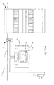
- the system 1 comprises a circuit and display unit 2 which houses flow interface and user interface circuits and which receives inputs from a current transformer 3.
- the unit 2 comprises a housing 4 and a display 5 which provides electricity flow information in an manner which is very clear and easy to read.
- the display 5 comprises upper and lower alphanumeric sequences 6 and 7, a display ramp 8, a program mode indicator 9, and a tamper alarm indicator 10.
- the unit 2 also includes a red LED 11 mounted beside the display 5.
- the Led 11 is a high intensity broad angle LED, visible from a wide area.
- the system 1 is installed by a user simply inserting the plug 16 into a conventional socket, and clipping the current transformer 3 in place around the relevant cable.
- the system 1 may alternatively be hard-wired into a distribution board if desired.
- the system 1 monitors both current flow and voltage level in a circuit in a non-intrusive manner. These signals are processed by both flow interface and user interface circuits within the unit 2.
- a microprocessor within the user interface circuit is programmable to provide cost or usage information according to parameters inputted by the user. These values may be accumulated cost and consumption values between a reset period and the current time or they may be historical accumulated costs for previous periods.
- An important aspect of the system 1 is that in addition to providing accumulated cost and/or usage data 7, it also provides a dynamic real time visual indication of current consumption. This is by way of the ramp 8 which has ten segments increasing in height in a ramp configuration. One of these segments is illuminated at any one point in time to indicate the level of the current consumption at that point in time. Another very important aspect is use of the flashing LED 11. This LED flashes at a rate which is proportional to the current consumption. This is very important. For example, if one is leaving a house the flashing LED 11 provides an immediate clearly-visible indication of the level of electricity consumption. This may, for example, indicate that an appliance has been inadvertently left switched on. This is very important for safety, as it may indicate, for example, that a heater or other potentially dangerous appliance has been inadvertently left switched on.
- the indicator 9 indicates that the unit 2 is in program mode and the indicator 10 is a tamper indicator. Tamper detection is described in more detail below.
- the unit 2 provides important accumulated data which is up to date in real time, and also provides data indicating the instantaneous consumption. This effectively provides a dual function for the system, and the latter function is extremely important for day-to-day use.
- the unit 2 comprises a set of buttons 15 which allow a user to perform functions such as setting time, resetting the cost calculation, and setting peak and off-peak hours on a 24-hour clock basis.
- a conventional 3-pin plug 16 provides mains power to the unit and is used by it to determine the voltage level in the electricity supply being monitored.
- the current transformer 3 (described in more detail below with reference to Figs. 3 and 4) is clipped in place around a power supply cable 17 carrying the supply being monitored. This provides a current level measurement to the unit 2.
- the unit 2 is shown mounted close to a conventional circuit breaker and distribution panel 18.
- the casing 4 includes a cover 19 which is normally used for installation. It requires use of a tool for removal, and this reveals a socket 20 for connection to the current transformer 3 and mains terminals 21.
- a microswitch and plunger/spring assembly 45 which is normally in contact with a protruding part 46 of the cover 19 detects opening of the cover 19 after installation and this is recorded as an alarm.
- the housing 4 houses a front, user interface circuit 72 and a rear, flow interface circuit 50. Both of these circuits are described in more detail below with reference to Figs. 5 and 6.
- the circuits 50 and 72 are interconnected by a ribbon cable.
- a potentiometer for calibration is mounted on the user interface circuit 72 in a location where it may be accessed by simply removing the cover 19.
- the user interface circuit 72 PCB is fixed in position on pillars 47 which are part of the moulding of the front part of the housing 4. This avoids the need for PCB stand-offs between boards and gives excellent alignment with keypad contacts.
- the keypad fits directly onto the user interface circuit 72 by engagement of plugs on the keypad with apertures in the PCB. This also provides excellent keypad alignment.
- the LCD display area is configured to allow light from above to enter at an angle of 45°. This improves clarity of the LCD display because it allows ceiling lights to provide effective illumination.
- the LCD lens is held in place in a cambered display area of the front of the housing 4 by plastics walls which are part of the front of the cover.
- the rear housing part incorporates strain-relief formations for both a mains cable and for a signal cable from the current transformer 3.
- the unit 2 comprises a mounting plate 22 having several screw holes to provide excellent versatility for mounting onto a wall 24 or conduit box or panel.
- the housing 4 rests on a lower ledge 25 of the mounting plate 22 and engages upstanding tabs 26. It will be apparent for Fig. 1(c) that the mounting plate 22 allows cables to be trained through a small opening 27 for rear cable entry, or alternatively a blank 28 may be knocked out for entry via minitrunking.
- the current transformer 3 comprises a hinged part 30 which has an elongate recess 31 and a socket 32 for receiving a plug 33 of a signal cable connected to the unit 2.
- the hinged part 30 is hinged to a base 34 having an elongate recess 35 co-operating with the recess 31.
- the base 34 is mounted over a transformer 37 which is connected by a signal cable 38 to a connector 30 which connects with the plug 33 to provide a current signal.
- These latter components are mounted within a casing 40.
- the current transformer 3 may be very easily connected to monitor current flow in a cable by simply closing the hinged part 30 over the cable so that it runs through the recesses 31 and 35. The level of current flow is picked up by the transformer 37. which supplies a signal proportional to the current flow.
- Tampering is detected because it is not possible to disconnect the transformer without first disconnecting the plug 33, thus providing a tamper indication.
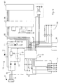
- the unit houses a flow interface circuit 50.
- the circuit 50 comprises mains terminals 51 for receiving a mains supply, in this embodiment 230V. This is passed through a potential divider 52 and a filter 53. This provides a sense input to a voltage-to-frequency converter 65 such as that marketed by Analog Devices under the code name AN-7750TM .
- the terminals 51 are also connected to an anti-tamper circuit 54 which comprises a detector in the unit 2 to detect opening of the housing.
- the detector comprises the microswitch and plunger assembly 45. When the cover is closing the plunger pushes against the spring, which in turn activates the microswitch.
- This circuit passes through a transient filter 56 and terminates in a connector 57.
- the current transformer 3 provides a signal on a signal line 60. This is converted to a voltage signal by a current-to-voltage converter 61.
- the voltage-to-frequency converter 65 receives two voltage sense inputs, one from the potential divider 52 and the filter 53 indicating the mains voltage level, and one from the current-to-voltage converter 61 indicating the mains current level.
- the converter 65 provides an output signal on a line 70 connected to the connector 57.
- the output signal is in the form of pulses, the frequency of which is proportional to the power consumption.
- the connector 57 is connected to a user interface circuit 72 which processes the pulse signal on the line 70 in order to generate user information.
- Keypad circuitry 75 is connected to the keypads on the unit 2 and this allows user programming of a microprocessor 76 to set various configurations of output data using the real time and dynamic power consumption inputs.
- the user interface circuit 72 also comprises a battery protection circuit 77 for the microprocessor 76.
- Signal lines from the connector 57 are indicated by the numeral 78 and the pulse signal is also directed to the LED 11 as illustrated in Fig. 6. Thus, without a need for any processing to take place, the LED 11 provides a dynamic real time and very clear visual indication of current consumption.
- Oscillators 79 provide clock signals for the microprocessor 76.
- the microprocessor 76 processes the various inputs in order to generate the information which is displayed on the display unit 5. This is by way of output LCD conductors 85 connected to a LCD driver 86, in turn connected to an LCD 87 which provides the alphanumeric sequences 6 and 7 and the ramp 8.
- Both of the circuits 50 and 72 include a large number of test pads for effective automatic in-circuit testing.
- the microprocessor 76 is also connected to an I 2 C bus 90 and to various links 91 which allow settings to be hard-wired.
- One such setting is domestic or commercial selection. In the domestic selection there may be no provision for a landlord PIN or anti-tamper function. This allows very simple product configuration.
- the current transformer 3 is connected at the appropriate electrical cable to sense the current flow in the cable.
- This may be the primary mains cable into a building, a cable of a subcircuit, or indeed a cable to a particular appliance or group of appliances. Voltage is very conveniently measured by simply tapping off the voltage supply to the unit itself. This is typically quite stable at 230V AC.
- the system 1 may be used in a non-intrusive manner to monitor power consumption for one or a variety of different circuits within a building.
- the cost may be displayed in French Francs. Deutschmarks, Dollars, Euros, or Pounds. Also, as described above, the cost may be for a period between the last reset and the present time, or for a previous period, or for an on-going set of periods such as night rate or day-rate metering including accumulated night costs and accumulated day costs separately. Also, the interface circuit retains the last bill totals so that the user can very easily check the accumulated totals for the last billing period. In addition, the user is provided with a very clear and visible indication of the present rate of consumption. This acts, in effect, as a high-consumption alarm so that the system has a dual purpose of both providing cost information and also an alarm for consumption the present time.
- the microprocessor is also programmed to recognise a special key sequence inputted by a user if the PIN is forgotten/lost. This allows a new PIN to be set without recourse to the manufacturer. However, following this procedure the tamper indicator 10 flashes for twenty-one days afterwards. This provides a warning to the user if a non-authorised user attempted the procedure. This activation of the tamper indicator 10 can not be stopped before expiry of the twenty-one day period.
- Versatility achieved by programming the microprocessor 76 is very useful.
- electricity utilities provide numerous tariff structures which are available to consumers. It is important for the consumer to choose the most appropriate structure and this can be greatly facilitated by use of the system 1 over a period of time to indicate the level of consumption for different time periods. This can be very important for minimising the power costs of an organisation.
- the microprocessor is programmed to calculate and display cost on the basis of different unit costs for usage bands as set up in tarriff structures.
- the basic architecture of the system 1 lends itself to excellent versatility whereby it may be used in a range of different applications.
- Its architecture comprises a sensor which in one embodiment is a current transformer; a flow interface, which in this embodiment is the flow interface circuit 50; and a user interface which in this embodiment is the interface circuit 72 and the associated display 5 and the keypad 12.
- the sensor may be a different type of sensor such as a fluid flow sensor which generates a voltage signal proportional to the flow rate of a medium such as gas or water.
- the flow interface circuit processes such a signal in a manner equivalent to that for electricity and generates a pulse signal which is proportional to the flow rate.
- This signal is available for use by one or a number of different user interfaces and the connection may be wired or wireless.
- a flow interface and associated sensor may be mounted in a transformer or meter room of a large factory, however, the user interface may be mounted in an office some distance away whereby a person with responsibility for cost control can conveniently monitor electricity cost.
- a central PC may receive flow data from a flow interface in every apartment in an apartment block.
- the user interface on a central monitoring station may be remote for large-scale centralised monitoring.
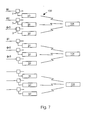
- the tamper circuits 54 of the flow interfaces may be linked to form a complete circuit for all phases.
- Such an arrangement is illustrated diagrammatically in Fig. 7, in which there are three supplies 100, 101, and 102 in a large industrial plant. Each supply comprises three phases and there is a current transformer 3 and a flow interface circuit 50 associated with each phase. There is only one user interface 104 per supply, however, there may be multiple user interfaces with wired or wireless connections to the associated flow interface circuits 50.
- the basic architecture of the system 1 provides excellent versatility both in the nature of the medium being monitored, and also in the nature of the user interaction which is required.
- the system may also take the form of a small, portable, weatherproof unit which may be mounted on a temporary power supply, for example in a building site. This provides a cost indication for power consumption on a temporary basis.
- the system would be very useful for builders or trades people.
- the system may alternatively be mounted in a machine to provide a power consumption cost for a pre-set time period, or on a job-by-job basis. For example, moulding machines consume large quantities of power and this application would be extremely useful and would allow an operator to invoice the actual cost of electricity for a particular job.
- the interface may be connected to an input device whereby it resets when the input device is activated by a person reading the meter. This allows the system to synchronise with billing periods.
- the flow interface may sense flow according to a meter such as an electricity utility meter. In this embodiment, power may be sensed using the shunt resistor technique wired directly to the supply.
- Another embodiment of the invention may involve monitoring wattless power/power factor, particularly in industrial environments.
- the system may comprise a printer or a printer driver for printing of data. Tampering may be detected by mechanical tamper-evident arrangements on the housing such as tamper-evident seals.
Landscapes
- Engineering & Computer Science (AREA)
- Power Engineering (AREA)
- Physics & Mathematics (AREA)
- General Physics & Mathematics (AREA)
- Arrangements For Transmission Of Measured Signals (AREA)
Priority Applications (3)
| Application Number | Priority Date | Filing Date | Title |
|---|---|---|---|
| EP99650108A EP1102073A1 (fr) | 1999-11-15 | 1999-11-15 | Surveillance d'un flux en temps réel |
| EP00650190A EP1102072A1 (fr) | 1999-11-15 | 2000-11-15 | Surveillance de flux en temps réel |
| IE20000923A IE20000923A1 (en) | 1999-11-15 | 2000-11-15 | Real time flow monitoring |
Applications Claiming Priority (1)
| Application Number | Priority Date | Filing Date | Title |
|---|---|---|---|
| EP99650108A EP1102073A1 (fr) | 1999-11-15 | 1999-11-15 | Surveillance d'un flux en temps réel |
Publications (1)
| Publication Number | Publication Date |
|---|---|
| EP1102073A1 true EP1102073A1 (fr) | 2001-05-23 |
Family
ID=8242606
Family Applications (1)
| Application Number | Title | Priority Date | Filing Date |
|---|---|---|---|
| EP99650108A Withdrawn EP1102073A1 (fr) | 1999-11-15 | 1999-11-15 | Surveillance d'un flux en temps réel |
Country Status (2)
| Country | Link |
|---|---|
| EP (1) | EP1102073A1 (fr) |
| IE (1) | IE20000923A1 (fr) |
Cited By (11)
| Publication number | Priority date | Publication date | Assignee | Title |
|---|---|---|---|---|
| FR2831263A1 (fr) * | 2001-10-22 | 2003-04-25 | Solendata | Procede et dispositif d'acquisition et de collecte de grandeurs physiques mesurables |
| DE102004036048B4 (de) * | 2004-07-24 | 2008-01-31 | Lehn, F. Heinrich, Dr.-Ing. | System zur Anzeige des Verbrauchs elektrischer Energie |
| WO2009109755A2 (fr) * | 2008-03-04 | 2009-09-11 | Sentec Limited | Système de mesure de puissance, procédé et/ou unités |
| WO2012145295A3 (fr) * | 2011-04-19 | 2013-09-19 | Schneider Electric It Corporation | Système de capteurs intelligents dans un panneau de commande électrique |
| US8660810B2 (en) | 2011-04-19 | 2014-02-25 | Schneider Electric It Corporation | System and method to calculate RMS current and true power in a multidrop sensor network |
| ES2469098A1 (es) * | 2012-12-14 | 2014-06-17 | Francisco Javier P�REZ DE EULATE P�REZ FLOR | Sistema para medir el coste del consumo eléctrico de aparatos eléctricos |
| US9146259B2 (en) | 2011-04-19 | 2015-09-29 | Schneider Electric It Corporation | Smart current transformers |
| US9638726B2 (en) | 2012-04-12 | 2017-05-02 | Schneider Electric It Corporation | System and method for detecting branch circuit current |
| US9804201B2 (en) | 2012-04-25 | 2017-10-31 | Schneider Electric It Corporation | Current monitoring device |
| US9851382B2 (en) | 2012-12-27 | 2017-12-26 | Schneider Electric USA, Inc. | Power meter with current and phase sensor |
| US9973036B2 (en) | 2013-12-31 | 2018-05-15 | Schneider Electric It Corporation | Automatic sub-millisecond clock synchronization |
Citations (5)
| Publication number | Priority date | Publication date | Assignee | Title |
|---|---|---|---|---|
| DE3033095A1 (de) * | 1980-09-03 | 1982-04-01 | Aweco Apparate- und Gerätebau GmbH & Co KG, 7995 Neukirch | Stromverbrauchszaehler |
| GB2183852A (en) * | 1985-11-27 | 1987-06-10 | Triad Communications Inc | Utility meter |
| US5406495A (en) * | 1993-02-01 | 1995-04-11 | Systems Analysis And Integration, Inc. | Substation load distribution monitor system |
| US5589764A (en) * | 1991-03-05 | 1996-12-31 | Lee; Graham S. | Meter for measuring accumulated power consumption of an electrical appliance during operation of the appliance |
| GB2309086A (en) * | 1996-01-03 | 1997-07-16 | Donald Christopher Stickland | Utility metering arrangement |
-
1999
- 1999-11-15 EP EP99650108A patent/EP1102073A1/fr not_active Withdrawn
-
2000
- 2000-11-15 IE IE20000923A patent/IE20000923A1/en not_active IP Right Cessation
Patent Citations (5)
| Publication number | Priority date | Publication date | Assignee | Title |
|---|---|---|---|---|
| DE3033095A1 (de) * | 1980-09-03 | 1982-04-01 | Aweco Apparate- und Gerätebau GmbH & Co KG, 7995 Neukirch | Stromverbrauchszaehler |
| GB2183852A (en) * | 1985-11-27 | 1987-06-10 | Triad Communications Inc | Utility meter |
| US5589764A (en) * | 1991-03-05 | 1996-12-31 | Lee; Graham S. | Meter for measuring accumulated power consumption of an electrical appliance during operation of the appliance |
| US5406495A (en) * | 1993-02-01 | 1995-04-11 | Systems Analysis And Integration, Inc. | Substation load distribution monitor system |
| GB2309086A (en) * | 1996-01-03 | 1997-07-16 | Donald Christopher Stickland | Utility metering arrangement |
Cited By (15)
| Publication number | Priority date | Publication date | Assignee | Title |
|---|---|---|---|---|
| FR2831263A1 (fr) * | 2001-10-22 | 2003-04-25 | Solendata | Procede et dispositif d'acquisition et de collecte de grandeurs physiques mesurables |
| DE102004036048B4 (de) * | 2004-07-24 | 2008-01-31 | Lehn, F. Heinrich, Dr.-Ing. | System zur Anzeige des Verbrauchs elektrischer Energie |
| WO2009109755A2 (fr) * | 2008-03-04 | 2009-09-11 | Sentec Limited | Système de mesure de puissance, procédé et/ou unités |
| WO2009109755A3 (fr) * | 2008-03-04 | 2009-12-30 | Sentec Limited | Système de mesure de puissance, procédé et/ou unités |
| US8666685B2 (en) | 2011-04-19 | 2014-03-04 | Schneider Electronic IT Corporation | System of intelligent sensors in an electrical panelboard |
| US8660810B2 (en) | 2011-04-19 | 2014-02-25 | Schneider Electric It Corporation | System and method to calculate RMS current and true power in a multidrop sensor network |
| WO2012145295A3 (fr) * | 2011-04-19 | 2013-09-19 | Schneider Electric It Corporation | Système de capteurs intelligents dans un panneau de commande électrique |
| CN103620424A (zh) * | 2011-04-19 | 2014-03-05 | 施耐德电气It公司 | 电气配电盘中的智能传感器系统 |
| US9146259B2 (en) | 2011-04-19 | 2015-09-29 | Schneider Electric It Corporation | Smart current transformers |
| CN103620424B (zh) * | 2011-04-19 | 2017-11-17 | 施耐德电气It公司 | 电气配电盘中的智能传感器系统 |
| US9638726B2 (en) | 2012-04-12 | 2017-05-02 | Schneider Electric It Corporation | System and method for detecting branch circuit current |
| US9804201B2 (en) | 2012-04-25 | 2017-10-31 | Schneider Electric It Corporation | Current monitoring device |
| ES2469098A1 (es) * | 2012-12-14 | 2014-06-17 | Francisco Javier P�REZ DE EULATE P�REZ FLOR | Sistema para medir el coste del consumo eléctrico de aparatos eléctricos |
| US9851382B2 (en) | 2012-12-27 | 2017-12-26 | Schneider Electric USA, Inc. | Power meter with current and phase sensor |
| US9973036B2 (en) | 2013-12-31 | 2018-05-15 | Schneider Electric It Corporation | Automatic sub-millisecond clock synchronization |
Also Published As
| Publication number | Publication date |
|---|---|
| IE20000923A1 (en) | 2001-05-16 |
Similar Documents
| Publication | Publication Date | Title |
|---|---|---|
| US7961111B2 (en) | Home control protection system | |
| CA2155539C (fr) | Dispositif automatique de lecture a distance de compteurs | |
| US4804957A (en) | Utility meter and submetering system | |
| US4901007A (en) | Portable electrical energy monitor | |
| CA2130434C (fr) | Methode et appareil d'essai pour compteur electronique | |
| US10467354B2 (en) | Visualization of electrical loads | |
| US5014213A (en) | System for use with polyphase utility meters for recording time of energy use | |
| CA2288875C (fr) | Dispositif de surveillance programmable de consommation electrique | |
| EP1102073A1 (fr) | Surveillance d'un flux en temps réel | |
| WO2008142425A1 (fr) | Appareil pour surveiller une consommation de ressource | |
| EP1102072A1 (fr) | Surveillance de flux en temps réel | |
| GB2041588A (en) | Apparatus for metering and displaying the cost of electrical energy consumption | |
| US20120046890A1 (en) | Energy monitoring device | |
| JP2001103622A (ja) | 宅内電気エネルギ計測システム | |
| GB2305333A (en) | Remote electric power reader apparatus | |
| US20120086632A1 (en) | Electric power information user interface, display method and apparatus thereof | |
| KR20080094746A (ko) | 벽면 매입형 통합분전반 | |
| KR101146847B1 (ko) | 주거단지의 에너지 데이터 관리 시스템 | |
| AU2018203426A1 (en) | Electricity meter | |
| JP2000193696A (ja) | 電力使用状態監視方法及びその装置 | |
| GB2416852A (en) | Power consumption cost monitoring device | |
| JP2005253130A (ja) | ロードサーベイメータを内蔵した分電盤及びそのロードサーベイメータ | |
| Directive et al. | LE-01d | |
| KR200268699Y1 (ko) | 어댑터형 간이 전력량 측정기기 | |
| RU216062U1 (ru) | Контроллер присоединения объектов микрогенерации к распределительной сети |
Legal Events
| Date | Code | Title | Description |
|---|---|---|---|
| PUAI | Public reference made under article 153(3) epc to a published international application that has entered the european phase |
Free format text: ORIGINAL CODE: 0009012 |
|
| STAA | Information on the status of an ep patent application or granted ep patent |
Free format text: STATUS: THE APPLICATION HAS BEEN WITHDRAWN |
|
| AK | Designated contracting states |
Kind code of ref document: A1 Designated state(s): AT BE CH CY DE DK ES FI FR GB GR IE IT LI LU MC NL PT SE |
|
| AX | Request for extension of the european patent |
Free format text: AL;LT;LV;MK;RO;SI |
|
| 18W | Application withdrawn |
Withdrawal date: 20010425 |