EP1101950A2 - Directional control valve - Google Patents
Directional control valve Download PDFInfo
- Publication number
- EP1101950A2 EP1101950A2 EP00202161A EP00202161A EP1101950A2 EP 1101950 A2 EP1101950 A2 EP 1101950A2 EP 00202161 A EP00202161 A EP 00202161A EP 00202161 A EP00202161 A EP 00202161A EP 1101950 A2 EP1101950 A2 EP 1101950A2
- Authority
- EP
- European Patent Office
- Prior art keywords
- chamber
- primary
- intake
- passage
- fluid
- Prior art date
- Legal status (The legal status is an assumption and is not a legal conclusion. Google has not performed a legal analysis and makes no representation as to the accuracy of the status listed.)
- Withdrawn
Links
- 239000012530 fluid Substances 0.000 claims abstract description 63
- 239000012528 membrane Substances 0.000 claims abstract description 47
- 238000006073 displacement reaction Methods 0.000 claims description 5
- 208000028659 discharge Diseases 0.000 claims 7
- 238000003780 insertion Methods 0.000 claims 1
- 230000037431 insertion Effects 0.000 claims 1
- 230000008030 elimination Effects 0.000 description 2
- 238000003379 elimination reaction Methods 0.000 description 2
- 230000002093 peripheral effect Effects 0.000 description 2
- 239000007787 solid Substances 0.000 description 2
- 238000007599 discharging Methods 0.000 description 1
- 229920001971 elastomer Polymers 0.000 description 1
- 239000000806 elastomer Substances 0.000 description 1
- 239000007788 liquid Substances 0.000 description 1
- 239000000463 material Substances 0.000 description 1
- 239000002184 metal Substances 0.000 description 1
- 238000012986 modification Methods 0.000 description 1
- 230000004048 modification Effects 0.000 description 1
- 238000000926 separation method Methods 0.000 description 1
- 229920003002 synthetic resin Polymers 0.000 description 1
- 239000000057 synthetic resin Substances 0.000 description 1
Images


Classifications
-
- F—MECHANICAL ENGINEERING; LIGHTING; HEATING; WEAPONS; BLASTING
- F15—FLUID-PRESSURE ACTUATORS; HYDRAULICS OR PNEUMATICS IN GENERAL
- F15B—SYSTEMS ACTING BY MEANS OF FLUIDS IN GENERAL; FLUID-PRESSURE ACTUATORS, e.g. SERVOMOTORS; DETAILS OF FLUID-PRESSURE SYSTEMS, NOT OTHERWISE PROVIDED FOR
- F15B13/00—Details of servomotor systems ; Valves for servomotor systems
- F15B13/02—Fluid distribution or supply devices characterised by their adaptation to the control of servomotors
- F15B13/04—Fluid distribution or supply devices characterised by their adaptation to the control of servomotors for use with a single servomotor
- F15B13/042—Fluid distribution or supply devices characterised by their adaptation to the control of servomotors for use with a single servomotor operated by fluid pressure
- F15B13/043—Fluid distribution or supply devices characterised by their adaptation to the control of servomotors for use with a single servomotor operated by fluid pressure with electrically-controlled pilot valves
- F15B13/0431—Fluid distribution or supply devices characterised by their adaptation to the control of servomotors for use with a single servomotor operated by fluid pressure with electrically-controlled pilot valves the electrical control resulting in an on-off function
-
- F—MECHANICAL ENGINEERING; LIGHTING; HEATING; WEAPONS; BLASTING
- F15—FLUID-PRESSURE ACTUATORS; HYDRAULICS OR PNEUMATICS IN GENERAL
- F15B—SYSTEMS ACTING BY MEANS OF FLUIDS IN GENERAL; FLUID-PRESSURE ACTUATORS, e.g. SERVOMOTORS; DETAILS OF FLUID-PRESSURE SYSTEMS, NOT OTHERWISE PROVIDED FOR
- F15B13/00—Details of servomotor systems ; Valves for servomotor systems
- F15B13/02—Fluid distribution or supply devices characterised by their adaptation to the control of servomotors
- F15B13/04—Fluid distribution or supply devices characterised by their adaptation to the control of servomotors for use with a single servomotor
- F15B13/0401—Valve members; Fluid interconnections therefor
- F15B13/0405—Valve members; Fluid interconnections therefor for seat valves, i.e. poppet valves
Abstract
Valve to control the direction of flow, which has a
primary intake for pressurised fluid, at least one
primary outlet for discharge, and at least one primary
usage way which is connected to a user, which define an
equivalent number of primary ways for intake/output of
the fluid, characterised in that it comprises the
following:
the valve comprises at least one pair of inner passages P1, P2, consisting of a first inner passage, which connects the primary intake 11 to the primary usage way 13, and of a second inner passage P2, which connects the primary usage way 13 to a primary outlet 12, each inner passage P1, P2 comprising two inlets for communication with respective primary ways 11, 12, 13; there are also provided means for closure of the inner passages P1, P2, each comprising a flexible membrane 21, 22 which is free to bend, and can assume a first position in which it is disposed on the two inlets themselves such as to close the latter, and a second position in which it is raised from the inlets themselves, such as to leave the latter free, and a transit chamber 23, 24 which is disposed on the flexible membrane, and is separated from the area of passage of the fluid, into which the two communication inlets open; and there are provided piloting means, which are controlled, and can introduce into one 23 of the transit chambers a pilot fluid with pressure which can thrust the respective membrane 21 into the said first position, in order to close the passage of the fluid, and simultaneously to allow the other transit chamber 24 to be discharged, in order to allow the membrane 22 to go into the said second position, such as to permit passage of the fluid; and vice versa.
the valve comprises at least one pair of inner passages P1, P2, consisting of a first inner passage, which connects the primary intake 11 to the primary usage way 13, and of a second inner passage P2, which connects the primary usage way 13 to a primary outlet 12, each inner passage P1, P2 comprising two inlets for communication with respective primary ways 11, 12, 13; there are also provided means for closure of the inner passages P1, P2, each comprising a flexible membrane 21, 22 which is free to bend, and can assume a first position in which it is disposed on the two inlets themselves such as to close the latter, and a second position in which it is raised from the inlets themselves, such as to leave the latter free, and a transit chamber 23, 24 which is disposed on the flexible membrane, and is separated from the area of passage of the fluid, into which the two communication inlets open; and there are provided piloting means, which are controlled, and can introduce into one 23 of the transit chambers a pilot fluid with pressure which can thrust the respective membrane 21 into the said first position, in order to close the passage of the fluid, and simultaneously to allow the other transit chamber 24 to be discharged, in order to allow the membrane 22 to go into the said second position, such as to permit passage of the fluid; and vice versa.
Description
- The present invention relates to a valve to control the direction of flow, which has a primary intake for pressurised fluid, at least one primary outlet for discharge, and at least one primary usage way which is connected to a user, which define an equivalent number of primary ways for intake/output of the fluid.
- A typical application for the said valves is in order to distribute the pressurised fluid to a machine which functions with fluids, for example a single- or double-effect piston cylinder.
- These valves normally have three ways (an intake, an outlet, and a usage way), and two positions for control of single-effect jacks, or they have four or five ways (an intake, one or two outlets, and two ways for usage), and two or three positions.
- These valves guide the fluid (liquid or gas) which they receive at their intake (with a specific pressure which is greater than atmospheric pressure) to one chamber or another of the user, and they discharge the remaining chamber.
- The known valves comprise a valve body, which has the said ways for intake/outlet of the flow, and is provided with an axial hole, into which there open corresponding channels for passage of the fluid, and a slider/shutter, which occupies the said axial hole, and slides in an axial direction, such as to define two or more positions; in the said positions the channels for the fluid are opened and closed selectively, such as to distribute the flow appropriately to the user.
- The object of the present invention is to provide a new valve to control the direction of flow, which has significant advantages in comparison with the known art, i.e.:
- high values in terms of length of service life;
- possibility of operating at high frequencies;
- possibility of working with flow rates of very different values, by means of simple changes of few component parts;
- possibility of embodiments with different structural forms;
- capacity for working in environments with very different temperatures and also relatively high temperatures, irrespective of expansion of the metal parts;
- lack of contact between the piloting fluid and the gaseous fluid; and
- possibility of operating with fluids which have high values of density and/or viscosity.
- These and other advantages are achieved by the invention in question, as characterised in the claims.
- The valve in question is based on the fact that it comprises:
- at least one pair of inner passages, consisting of a first inner passage, which connects the primary intake to the primary usage way, and of a second inner passage, which connects the primary usage way to a primary outlet, each inner passage comprising two inlets for communication with respective primary ways;
- means for closure of the inner passages, one for each inner passage, each comprising a flexible membrane which is free to bend, has a size such as to cover the inlets themselves, and can assume a first position in which it is disposed on the two inlets such as to cover the latter, and a second position in which it is raised from the inlets themselves, such as to leave the latter free, and a transit chamber which is disposed on the flexible membrane, and is separated from the area of passage of the fluid, into which the two communication inlets open; and
- piloting means, which are controlled, and can introduce into one of the transit chambers a pilot fluid with pressure which can thrust the respective membrane into the said first position, with force which is sufficient to prevent passage of the fluid, and simultaneously allow the other transit chamber to be discharged; and
- which means can allow the membrane to go into the said second position, to permit passage of the fluid; and vice versa.
-
- The invention is described in detail hereinafter with the assistance of the attached figures, which illustrate one embodiment by way of non-exclusive example.
- Figure 1 is a schematic representation of the valve in question, in a version with three ways;
- Figure 2 is a more detailed lateral view, partially in cross-section, of the valve in figure 1;
- Figure 2A is an enlarged detail of figure 2;
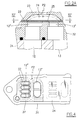
- Figure 3 is the cross-section according to the plane III-III in figure 2;
- Figure 4 is the cross-section according to the plane IV-IV in figure 2A;
- Figure 5A is an enlarged detail of figure 2, relating to a first piloting valve, in a first position;
- Figure 5B is the same detail as figure 5A, in a second position;
- Figure 6 is a schematic representation of the valve in question in a version with five ways; and
- Figure 7 is a more detailed lateral view, partially in cross-section, of the valve in figure 6.
-
- Reference is made firstly to an embodiment in which the valve in question, generally indicated as ... , is of the three-way type (figures 1 to 5B).
- The valve comprises a
monolithic valve body 30, which is formed from one or more bodies which are rendered integral with one another, in which the following primary intake/outlet ways are provided: - a
primary intake 11, by means of which pressurised fluid is supplied to thevalve 10, for example by means of a compressor orpump 14; - a
primary outlet 12, by means of which the fluid is discharged; and - a
primary usage way 13, which connects thevalve 10 to a user, for example the chamber 15' of ahydraulic jack 15. -
- (The adjective primary is used here to distinguish the above-described ways from those of the piloting valves, which are described hereinafter).
- In the
body 30 there is provided a pair of inner passages, i.e.: a first inner passage P1, which connects theprimary intake 11 to theprimary usage way 13, and a second inner passage P2, which connects theprimary usage way 13 to theprimary outlet 12. - Each of these inner passages P1, P2 comprises a transit chamber, respectively 23 and 24, each of which has a
lower base 25 which is flat (see in particular figure 2A), or is in the form of a spherical cap with the concavity facing upwards (not illustrated in the figures), onto which there open two adjacent inlets, each of which communicates directly with a corresponding primary way, and each of which has a respective axis which is spaced from the axis of the other inlet; these inlets thus have their own upper edges disposed substantially on a single plane (as illustrated in the figures), or on a common surface with a spherical cap (not illustrated in the figures). - In particular, the passage P1 comprises the
transit chamber 23, an inlet 13' which communicates with theusage way 13, and an inlet 11' which communicates with theintake 11; the passage P2 comprises thetransit chamber 24, aninlet 13" which communicates with theusage way 13, and aninlet 12" which communicates with theoutlet 12. - In the inner passage P1, there are also provided respective means for closure of the flow, which comprise a
flexible membrane 21 which is free to bend, and has a size such as to cover the respective pair of inlets 11' and 13', which are subtended by the same respective passage. Themembrane 21 normally adheres to thebase 25 of therespective chamber 23, and separates this chamber from the area of passage of the fluid, into which the two inlets 11' and 13' open. - Similarly, in the inner passage P2 there are provided means for closure of the flow, which comprise a
flexible membrane 22 which is free to bend, and has a size such as to cover the respective pair ofinlets 12" and 13", which are subtended by the same respective passage P2. Themembrane 22 normally adheres to thebase 25 of therespective chamber 24, and separates this chamber from the area of passage of the fluid, into which the twoinlets 12" and 13" open. - Each
membrane respective inlets 11' and 13' or 13" and 12", such as to close the latter, and a second position (illustrated as a broken line in figure 2A), in which it is raised from the inlets themselves, such as to leave the latter free. - Advantageously, the
membranes chamber - In addition, the
membranes inlets 11', 13' and 12", 13". - With the valve in question there are associated piloting means, which are controlled, and can introduce into one of the
transit chambers 23, 24 (for example into the chamber 23) a pilot fluid with pressure which can thrust therespective membrane 21, 22 (21 in the example) into the said first position, with force which is sufficient to prevent passage of the fluid, and allow theother transit chamber 24, 23 (24 in the example) to be discharged; and which means can allow therespective membrane 22, 21 (22 in the example) to go into the said second position, to permit passage of the fluid; and vice versa. - In operation, in order to close the passages P1 or P2, the pressure of the pilot fluid which acts on the
respective membrane inlets 11' and 13' or 13" and 12", must be such as to overcome the opposing force provided by the fluid which acts in the inlets beneath. - In particular, according to a preferred (but not exclusive) embodiment illustrated in the figures, as the pilot fluid, the piloting means use fluid taken from the
primary intake 11. In this case therefore, the thrust which acts in thetransit chamber membrane - It will be appreciated that the greater the value of the piloting pressure, the greater is the level of certainty that the membrane 36 will close the communication inlets.
- In order to open the passage P1 or P2 (passage open), the
transit chamber membrane inlets 11' and 13' or 13" and 12", and thus the fluid is free to pass from one inlet to the other, passing beneath themembrane - As already stated, the piloting means can assume two different configurations. In a first configuration, the
transit chamber 23 is pressurised, such as to close the passage P1, and simultaneously theother chamber 24 is discharged, such as to open the passage P2 (as illustrated in figure 1). In this configuration, theintake 11 is closed, and the user (for example the chamber 15' of the jack 15) is put into communication with thedischarge outlet 13. - In the second configuration (not illustrated in the figures), which is an alternative to the first configuration, the
transit chamber 24 is pressurised, such as to close the passage P2, and simultaneously theother chamber 23 is discharged, such as to open the passage P1. In this configuration, thedischarge 12 is closed, and the user (for example the chamber 15' of the jack 15) is put into communication with theinput 11, and thus receives pressurised fluid. - The
valve 10 thus carries out its main function of guiding the fluid towards the user, or of discharging the latter. - When two primary ways are both pressurised, as is the case for example between the
intake 11 and theusage way 13 in the second configuration, in order to close the corresponding passage (P1) when required, it is necessary to open the other passage (P2) simultaneously, such as to discharge one of the ways (the way 13), and thus reduce the pressure which is present in the passage (P1) in question, to the point where it is exceeded by the piloting thrust of themembrane 21. - According to a preferred (but not exclusive) embodiment, illustrated in the figures, the piloting means comprise a
first piloting valve 50 and asecond piloting valve 60, each of which comprises a ressurised fluid intake, respectively 51 and 61, a discharge, respectively 52 and 62, and a third way, respectively 53 and 63, which is connected to a transit chamber, respectively P1 and P2. The twointakes primary intake 11. Eachpilot valve own intake third way own discharge third way first pilot valve 50 has its own first position which is normal, and is piloted into the second position by the fluid which is present in thethird way 63 of thesecond pilot valve 60. - In particular, the said first piloting
valve 50 is contained in thesame valve body 30 which contains the primary ways (theprimary intake 11, theoutlet 12, and the usage way 13), as well as the communication inlets and the transit chambers. - In detail, the
first pilot valve 50 comprises an uppercylindrical chamber 71, and alower chamber 72 beneath, which are coaxial and communicate with one another. Thelower chamber 72 has avalve seat 73, in the section in which thechamber 72 communicates with thelower part 71a of thechamber 71, which puts the twochambers lower inlet 77, which opens onto the lower base of thelower chamber 72; both theinlet 77 and theseat 73 have a diameter which is smaller than that of thechamber 71. Thechamber 72 contains ashutter 74 with axial movement, which, by means of aseal 75, can close thevalve seat 73, when the shutter is thrust upwards, thus isolating thepart 71a from thechamber 72, and can close theinlet 77 by means of its own lower base 74', when the shutter is thrust downwards. There is connected to theshutter 74 anupper plunger 76, which slides in a sealed manner in thechamber 71, and separates hermetically thelower part 71a of thechamber 71 itself, from theupper part 71b. - A
spring 78 normally keeps theshutter 74 thrust upwards. - In its own lower part, the
lower chamber 72 is connected to thethird way 53, whereas theinlet 77 communicates with theintake 51. Thelower part 71a of thechamber 71 is connected to theoutlet 52, whereas theupper part 71b is connected by means of apilot duct 54 to thethird way 63 of thesecond valve 60. - When pressurised pilot fluid is inserted in the
upper part 71b of theupper chamber 71, theplunger 76 is displaced into the lower position, and together with the plunger there is displacement of theshutter 74, which, by means of its own base 74', closes theinlet 77 of theintake 51, and, simultaneously, via theseat 73, the passage from thechamber 72 to thelower part 71a of thechamber 71 is opened; theintake 51 is thus closed, and the communication between thethird way 53 and thedischarge 52 is opened (as illustrated in figure 5B). - When the
upper part 71b is discharged, theshutter 74 is displaced by thespring 78 into the upper position, in which it closes theseat 73, and leaves open theinlet 77, thus putting the latter into communication with the lower part of thelower chamber 72; thus theintake 51 and thethird way 53 are put into communication, whereas thedischarge 52 is closed (as illustrated in figure 5A). - The functioning of the
entire valve 10 is controlled by thesecond valve 60, which is a conventional valve with three-ways (61, 62 and 63) and two positions, controlled by an operator, for example by means of an electro-magnetic device. - When the
valve 60 is actuated such that it closes itsown intake 61, and discharges its own third way 63 (valve closed), firstly thetransit chamber 24 of the passage P2 is discharged, and then the passage itself is opened. Simultaneously, theupper part 71b of theupper chamber 71 of thevalve 50 is discharged, thus giving rise to displacement into the upper position of theshutter 74, and putting theintake 51 into communication with thethird way 53; consequently, thechamber 23 of the passage P1 is pressurised, and the passage itself is closed. This therefore provides the above-described first configuration (illustrated in figure 1). - On the other hand, when there is actuation of the
valve 60, such that theintake 61 is put into communication with its own third way 63 (valve open), firstly thetransit chamber 24 of the passage P2 is pressurised, and the passage itself is closed. Simultaneously, theupper part 71b of theupper chamber 71 is pressurised, thus giving rise to displacement into the lower position of theshutter 74, and putting into communication thethird way 53 and thedischarge 52; consequently thechamber 23 of the passage P1 is discharged, and the passage itself is closed. This therefore provides the above-described second configuration. - According to a different piloting system (not illustrated in the figures), the valve in question is piloted by means of a conventional valve to control the direction of the flow, with four or five ways and at least two positions, such as to provide the above-described two configurations.
- In particular, this pilot valve comprises a pressurised fluid intake, one or two discharge outlets, a first usage way, which is connected to one of the
transit chambers 23, and a second usage way, which is connected to theother transit chamber 24; this pilot valve has a first position, in which it connects its own intake to the first usage way, and connects the second usage way to its own outlet, and a second position, in which it connects the second usage way to its own intake, and the first usage way to its own outlet. In addition, the intake of the pilot valve communicates with theprimary intake 11. - By actuating this piloting valve in the first and in the second position, the
valve 10 is put respectively into the first and second said configurations. - Figures 6 and 7 illustrate an embodiment in which the
valve 10B in question differs from the three-way valve previously described, in that it has five ways. - In particular, in the
monolithic valve body 30, thevalve 10B comprises: - a
primary intake 11, by means of which pressurised fluid is supplied to thevalve 10B, for example by means of a compressor or pump 14; - two
primary outlets - a first
primary usage way 13a, which connects thevalve 10B to a first user, for example the first chamber 16' of ahydraulic jack 16; and - a second
primary usage way 13b, which connects thevalve 10B to a second user, for example thesecond chamber 16" of thesame jack 16. -
- The
body 30 also contains two pairs of inner passages, similarly to the case of the three-way valve, i.e. a first pair, comprising two passages P1a and P2a, and a second pair, comprising two passages P1b and P2b. In each pair there is provided a first inner passage P1a, P1b, which connects theprimary intake 11 to a respectiveprimary usage way primary usage way primary outlet - The said inner passages are the same as those for the three-way valve, and each comprise a respective transit chamber, indicated respectively as 23a, 24a in the first pair, and 23b, 24b in the second pair. Into each chamber there opens an adjacent pair of inlets:
- the passage P1a comprises the
transit chamber 23a, an inlet 13'a which communicates with theusage way 13a, and an inlet 11'a which communicates with theintake 11; - the passage P1b comprises the
transit chamber 23b, an inlet 13'b which communicates with theusage way 13b, and an inlet 11'b which communicates with theintake 11; - the passage P2a comprises the
transit chamber 24a, aninlet 13"a which communicates with theusage way 13a, and aninlet 12", which communicates with theoutlet 12a; and - the passage P2b comprises the
transit chamber 24b, aninlet 13"b which communicates with theusage way 13b, and aninlet 12"b which communicates with theoutlet 12b. -
- In addition, in each of the said inner passages, there is provided a respective means for closure of the flow, comprising a
respective membrane - With the
valve 10B there are associated piloting means, which differ from those provided for the three-way valve version, only in that each usage way 53 (of the first valve 50) and 63 (of the second valve 60) is divided into two branches. Theway 53 is divided into twobranches chamber 23a of the first passage P1a of the first pair, and to thechamber 24b of the second passage P2b of the second pair; theway 63 is divided into two branches 63a, 63b, which are connected to thechamber 24a of the second passage P2a of the first pair, and to thechamber 23b of the first passage P1b of the second pair. - Thus, the piloting means introduce into the
chamber 23a of the first passage P1a of the first pair, and into thechamber 24b of the second passage P2b of the second pair, a pilot fluid which has a pressure which can thrust the membrane into the said first position, in order to prevent passage of the fluid, and simultaneously to discharge thechamber 24a of the second passage P2a of the first pair, and thechamber 23b of the first passage P1b of the second pair, in order to allow the membrane to go into the said second position, such as to permit passage of the fluid; and vice versa. - To summarise, these piloting means operate similarly to the manner described for the version with three ways; the only difference is that one pair of passages P1a and P2a operates in a manner which is symmetrically opposed to the other pair of passages P1b and P2b; this means that when, in the first pair, the first passage P1a is closed and the second passage P2a is opened, simultaneously, in the second pair, the first passage P1b is opened and the second passage P2b is closed; and vice versa.
- In a first configuration, the
transit chambers other chambers intake 11 is connected only to thesecond usage way 13b, and thus to the second user (for example thechamber 16" of the jack 16), whereas the first user (chamber 16') is discharged via thefirst usage way 13a, which communicates with thedischarge 12a. - In the second configuration (not shown in the figures), which is an alternative to the first, the
transit chambers other chambers intake 11 is connected only to thefirst usage way 13b, and thus to the first user (for example the chamber 16' of the jack 16), whereas the second user (chamber 16") is discharged via thesecond usage way 13b, which communicates with thedischarge 12b. - According to a preferred (but not exclusive) structural embodiment, both in the three-way version and in the five-way version, the
valve body 30 comprises alower body 31, anintermediate body 32, and anupper body 33, which are substantially flat, and are rendered integral with one another in the form of a sandwich, with the respective horizontal surfaces adhering firmly to one another. - In the
lower body 31, there are provided the primary intake/outlet ways, i.e. theprimary intake 11, theprimary outlet 12, and theusage way 13. In theintermediate body 32 there are provided theinlets 11', 12', 13" and 12", which open onto the upper surface of the body 32 (which thus defines thebase 25 of thechambers 23 and 24). Thetransit chambers upper body 33. Themembranes upper body 33 and the upper surface of theintermediate body 32, and separate thechambers base 25 beneath, onto which the saidinlets 11', 13', 13" and 12" open (see in particular figures 2 and 3). - Similarly, in the five-way version (figure 7), in the
lower body 31, there are provided theprimary intake 11, theprimary outlets usage ways intermediate body 32 there are provided the various inlets 11'a, 11'b, 13'a, 13'b, 13"a, 13"b, 12"a and 12"b, which open onto the upper surface of the body 32 (which thus defines thebase 25 of thetransit chambers membranes upper body 33 and the upper surface of theintermediate body 32, and separate thetransit chambers base 25 beneath, onto which the said inlets 11'a, 11'b, 13'a, 13'b, 13"a, 13"b, 12"a and 12"b open. As already stated, the first pilotingvalve 50 is contained in thesame valve body 30. In particular, it is contained in theupper body 33, which, according to the embodiment illustrated in figure 7, consists of several flat components which are joined together in the form of a sandwich, which in turn is connected to the two bodies beneath it, i.e. 32 and 31. - The
various ducts pilot valves valve body 30, and in particular in theupper body 33. In this respect, thebody 33 comprises afirst component 331, which is substantially flat, in the lower, horizontal surface of which the transit chambers are provided, and asecond component 332, which is also flat, and adheres to the flat, horizontal upper surface of thefirst component 331. Above thesecond component 332, there is disposed athird component 333, the flat, horizontal, lower surface of which adheres to the upper surface of thesecond component 332. - The
second component 332 has a series ofchannels 39 which are suitably shaped, are recessed in its upper surface, are closed at the top by the lower surface of thethird component 333, and give rise, at least partially, to the various connection ducts between the transit chambers and the pilot valves. Other ducts (not shown in the figures) are provided inside theupper body 33. - Finally, on the upper surface of the
body 33, there is provided anupper component 34, which acts as a connection for the ways for intake, discharge and usage of thesecond pilot valve 60, which is disposed on the exterior of thevalve body 30, and is secured to the latter. - The inlets which function in a discharged condition when they are closed (for example the
inlets 12" and 13") have thin cross-pieces 37 (see figure 4), which act as a support grid, on which the correspondingmembrane - By means of the invention, there is elimination of the reciprocally mobile sliding parts which are provided in directional control valves of a known type. This therefore reduces drastically all the technical problems which are associated with these movements, including mainly wear. By this means, it is found that the service life of the valve is very long.
- In addition, the valve can function at frequencies which are relatively very high (up to 50 Hz), as a result of the low inertia of its moving parts, consisting only of the
flexible membranes - It is also ensured that there is contact-free separation of the piloting fluid and the fluid which is controlled.
- There is also considerable simplification of production of the valve, in particular because it is no longer necessary to produce solid parts which are connected to one another according to requirements, since the shutter is produced simply by means of a membrane which is secured to the body of the valve.
- Furthermore, again owing to the fact that in the present invention it is not necessary to produce solid parts which are connected to one another according to requirements, there are no particular technical problems associated with the expansion of the bodies; the valve can thus operate equally well at high or low temperatures.
- In addition, the reciprocal arrangement of the various inner passages and of the primary ways can be varied freely, and thus the valve can be produced according to various different geometric shapes. It will be appreciated that many modifications of a practical and applicative nature can be made to the invention in question, without departing from the context of the inventive concept, as claimed hereinafter.
Claims (10)
- Valve to control the direction of flow, which has a primary intake for pressurised fluid, at least one primary outlet for discharge, and at least one primary usage way which is connected to a user, which define an equivalent number of primary ways for intake/output of the fluid, characterised in that it comprises:at least one pair of inner passages, consisting of a first inner passage, which connects the primary intake to the primary usage way, and of a second inner passage, which connects the primary usage way to a primary outlet, each inner passage comprising two inlets for communication with respective primary ways;means for closure of the inner passages, each comprising a flexible membrane which is free to bend, has a size such as to cover the respective two communication inlets, and can assume a first position in which it is disposed on the two inlets, such as to close the latter, and a second position in which it is raised from the inlets themselves, such as to leave the latter free, and a transit chamber which is disposed on the flexible membrane, and is separated from the area of passage of the fluid, into which the two communication inlets open; andpiloting means, which are controlled, and can introduce into one of the transit chambers a pilot fluid with pressure which can thrust the respective membrane into the said first position, with force which is sufficient to prevent passage of the fluid, and simultaneously allow the other transit chamber to be discharged; andwhich means can allow the respective membrane to go into the said second position, to permit passage of the fluid; and vice versa.
- Control valve according to claim 1, characterised in that the said primary intake/outlet ways, the said inner passages and the corresponding inlets, and the transit chambers, are all contained in a monolithic valve body, and in addition each inner passage comprises two adjacent inlets, which are disposed on the lower base of the transit chamber, each of which communicates directly with a respective primary way, and each of which has an axis which is spaced from the axis of the other inlet, these inlets having their own upper edges disposed substantially on a single plane, and the membrane being completely free to bend, and to assume a first position of contact with the entire perimeter of both the inlets.
- Control valve according to claim 1, characterised in that the piloting means use fluid taken from the primary intake as the pilot fluid.
- Control valve according to claim 1, characterised in that the said piloting means comprise:a first and a second piloting valve, each comprising a pressurised fluid intake in common with the other piloting valve, a discharge, and a third way which is connected to a respective transit chamber;each pilot valve having a first position, in which it puts its own intake into communication with its own third way, and a second position, in which it puts its own discharge into communication with the said third way;the first pilot valve having the first position, which is normal, and being piloted into the second position by the fluid which is present in the third way of the second pilot valve.
- Control valve according to claim 4, characterised in that the first piloting valve comprises:an upper cylindrical chamber and a lower chamber beneath, which is coaxial relative to, and communicates with, the first chamber, with a valve seat in the section for communication with the lower part of the chamber, and a lower inlet, which opens onto the lower base of the lower chamber; the said inlet and the said seat having a diameter which is smaller than that of the chamber;a shutter with axial movement, which is disposed in the chamber, and which by means of a seal can close the valve seat when it is thrust upwards into the high position, thus isolating part of the chamber, and can close the inlet, with its own lower base, when it is thrust downwards into the low position;an upper plunger, which is connected to the shutter, slides in a sealed manner in the chamber, and separates the lower part of the chamber itself hermetically from the upper part;a spring which normally keeps the shutter thrust upwards;the lower chamber being connected in its own lower part to the third way, and the inlet being connected to the intake;the lower part of the chamber being connected to the outlet, whereas the upper part is connected by means of a pilot duct to the third way of the second valve;the insertion of pressurised fluid in the upper part of the upper chamber giving rise to displacement of the shutter into the said lower position, in order to close the inlet of the intake, and open the passage, through the seat, from the chamber to the lower part of the chamber; anddischarge of the upper part of the upper chamber giving rise to displacement of the shutter into the upper position, in order to close the outlet and open the communication between the inlet and the third way.
- Control valve according to claim 4, characterised in that the said first piloting valve is contained in a single valve body, which comprises the primary intake/outlet ways, the communication inlets and the transit chambers.
- Control valve according to claim 3 and claim 4, characterised in that the intake to the first and second piloting valve communicates with the primary input.
- Control valve according to claim 1, characterised in that the said piloting means comprise a pilot valve to control the direction of flow, which has a pressurised fluid intake, one or more discharge outlets, a primary usage way which is connected to one of the transit chambers, and a second usage way which is connected to the other transit chamber, the said pilot valve having a first position in which it connects its own input to the primary usage way, and simultaneously connects the second usage way to its own outlet, and a second position, in which it connects the second usage way to its own intake, and simultaneously connects the first usage way to its own outlet.
- Control valve according to claims 3 and 8, characterised in that the intake of the pilot valve communicates with the primary intake.
- Control valve according to claim 1, with a primary pressurised fluid intake, two primary discharge outlets, and at least two primary usage ways which are connected to a user, characterised in that it comprises two pairs of inner passages, each pair comprising a first said inner passage, which connects the primary intake to a respective primary usage way, and a said second inner passage, which connects the same primary usage way and a primary outlet;
the piloting means being able to introduce into the chamber of the first passage P1a of the first pair, and into the chamber of the second passage of the second pair, a pilot fluid which has pressure which can thrust the membrane into the said first position, in order to prevent passage of the fluid, and simultaneously to discharge the chamber of the second passage of the first pair, and the chamber of the first passage of the second pair, in order to allow the membrane to go into the said second position, such as to permit passage of the fluid; and vice versa.
Applications Claiming Priority (2)
| Application Number | Priority Date | Filing Date | Title |
|---|---|---|---|
| ITRE990119 | 1999-11-17 | ||
| IT1999RE000119A IT1311050B1 (en) | 1999-11-17 | 1999-11-17 | FLOW DIRECTION CONTROL VALVE. |
Publications (1)
| Publication Number | Publication Date |
|---|---|
| EP1101950A2 true EP1101950A2 (en) | 2001-05-23 |
Family
ID=11399515
Family Applications (1)
| Application Number | Title | Priority Date | Filing Date |
|---|---|---|---|
| EP00202161A Withdrawn EP1101950A2 (en) | 1999-11-17 | 2000-06-21 | Directional control valve |
Country Status (2)
| Country | Link |
|---|---|
| EP (1) | EP1101950A2 (en) |
| IT (1) | IT1311050B1 (en) |
-
1999
- 1999-11-17 IT IT1999RE000119A patent/IT1311050B1/en active
-
2000
- 2000-06-21 EP EP00202161A patent/EP1101950A2/en not_active Withdrawn
Also Published As
| Publication number | Publication date |
|---|---|
| ITRE990119A1 (en) | 2001-05-17 |
| IT1311050B1 (en) | 2002-02-28 |
| ITRE990119A0 (en) | 1999-11-17 |
Similar Documents
| Publication | Publication Date | Title |
|---|---|---|
| CA2102901C (en) | Fluid control valve arrangement | |
| ATE354025T1 (en) | DOUBLE DIAPHRAGM PUMP | |
| JPH0694906B2 (en) | Slip valve | |
| CA1208102A (en) | Pilot operated supply and waste control valve | |
| JPH0744560U (en) | Front cutoff valve | |
| US3760843A (en) | Multi-way directional fluid flow control valve arrangement | |
| US4458718A (en) | Spool valve and seal having zero leakage | |
| EP1803980B1 (en) | Hollow piston valve | |
| EP1146234A3 (en) | Hydraulic system with shadow poppet valve | |
| EP1114954A2 (en) | Two-port valve | |
| CN1316189C (en) | Fluid valve device | |
| US11448204B2 (en) | Diaphragm pump with valve switching device | |
| CN107120329B (en) | Proportional pressure controller with isolation valve module | |
| EP1101950A2 (en) | Directional control valve | |
| EP1029185B1 (en) | A valve arrangement | |
| US3782682A (en) | Fluid flow controller | |
| USRE29481E (en) | Multi-way directional fluid flow control valve arrangement | |
| US4374485A (en) | Single annular membrane type of pneumatic positioner | |
| US2881801A (en) | Pilot-operated three-way valve | |
| JPH0238768A (en) | Fluid control valve | |
| KR102128375B1 (en) | Three way solenoid valve | |
| EP1484540B1 (en) | Actuating membrane in particular for pneumatic valves | |
| US2882929A (en) | Pilot-operated three-way diversion valve | |
| JPH0434283Y2 (en) | ||
| JP2534813Y2 (en) | Stacking manifold |
Legal Events
| Date | Code | Title | Description |
|---|---|---|---|
| PUAI | Public reference made under article 153(3) epc to a published international application that has entered the european phase |
Free format text: ORIGINAL CODE: 0009012 |
|
| AK | Designated contracting states |
Kind code of ref document: A2 Designated state(s): AT BE CH CY DE DK ES FI FR GB GR IE IT LI LU MC NL PT SE |
|
| AX | Request for extension of the european patent |
Free format text: AL;LT;LV;MK;RO;SI |
|
| 18D | Application deemed to be withdrawn |
Effective date: 20021231 |
|
| STAA | Information on the status of an ep patent application or granted ep patent |
Free format text: STATUS: THE APPLICATION IS DEEMED TO BE WITHDRAWN |
|
| R18D | Application deemed to be withdrawn (corrected) |
Effective date: 20030103 |