EP1101718B1 - High capacity automatic sheet input system for a reproduction apparatus - Google Patents
High capacity automatic sheet input system for a reproduction apparatus Download PDFInfo
- Publication number
- EP1101718B1 EP1101718B1 EP00124823A EP00124823A EP1101718B1 EP 1101718 B1 EP1101718 B1 EP 1101718B1 EP 00124823 A EP00124823 A EP 00124823A EP 00124823 A EP00124823 A EP 00124823A EP 1101718 B1 EP1101718 B1 EP 1101718B1
- Authority
- EP
- European Patent Office
- Prior art keywords
- sheet
- stack
- sheets
- shipping container
- copy
- Prior art date
- Legal status (The legal status is an assumption and is not a legal conclusion. Google has not performed a legal analysis and makes no representation as to the accuracy of the status listed.)
- Expired - Lifetime
Links
Images


Classifications
-
- B—PERFORMING OPERATIONS; TRANSPORTING
- B65—CONVEYING; PACKING; STORING; HANDLING THIN OR FILAMENTARY MATERIAL
- B65H—HANDLING THIN OR FILAMENTARY MATERIAL, e.g. SHEETS, WEBS, CABLES
- B65H1/00—Supports or magazines for piles from which articles are to be separated
- B65H1/26—Supports or magazines for piles from which articles are to be separated with auxiliary supports to facilitate introduction or renewal of the pile
- B65H1/266—Support fully or partially removable from the handling machine, e.g. cassette, drawer
-
- B—PERFORMING OPERATIONS; TRANSPORTING
- B65—CONVEYING; PACKING; STORING; HANDLING THIN OR FILAMENTARY MATERIAL
- B65H—HANDLING THIN OR FILAMENTARY MATERIAL, e.g. SHEETS, WEBS, CABLES
- B65H1/00—Supports or magazines for piles from which articles are to be separated
- B65H1/08—Supports or magazines for piles from which articles are to be separated with means for advancing the articles to present the articles to the separating device
- B65H1/14—Supports or magazines for piles from which articles are to be separated with means for advancing the articles to present the articles to the separating device comprising positively-acting mechanical devices
-
- B—PERFORMING OPERATIONS; TRANSPORTING
- B65—CONVEYING; PACKING; STORING; HANDLING THIN OR FILAMENTARY MATERIAL
- B65H—HANDLING THIN OR FILAMENTARY MATERIAL, e.g. SHEETS, WEBS, CABLES
- B65H2405/00—Parts for holding the handled material
- B65H2405/10—Cassettes, holders, bins, decks, trays, supports or magazines for sheets stacked substantially horizontally
- B65H2405/15—Large capacity supports arrangements
-
- B—PERFORMING OPERATIONS; TRANSPORTING
- B65—CONVEYING; PACKING; STORING; HANDLING THIN OR FILAMENTARY MATERIAL
- B65H—HANDLING THIN OR FILAMENTARY MATERIAL, e.g. SHEETS, WEBS, CABLES
- B65H2405/00—Parts for holding the handled material
- B65H2405/30—Other features of supports for sheets
- B65H2405/31—Supports for sheets fully removable from the handling machine, e.g. cassette
- B65H2405/311—Supports for sheets fully removable from the handling machine, e.g. cassette and serving also as package
Definitions
- the present invention relates to an improved copy or print sheets loading and feeding system for a reproduction apparatus, in particular, for improved ease and convenience of loading a large and heavy stack of a large number of sheets of paper or other image substrate material into a high sheet capacity input of a reproduction apparatus, for providing uninterrupted or continuous feeding of a large number of sheets.
- reproduction apparatus such as xerographic and other printers or multifunction machines
- the disclosed system is particularly suitable for integration into or use with what is known in the art as a high capacity or "high-cap” feeder. It can enable uninterrupted feeding of the sheets to be printed from a large stack thereof, by automatic lifting of, and maintaining the vertical position of, the top of the stack with the sheet feeder which is feeding the sheets sequentially to the printer as the stack is depleted by that sheet feeding. It can provide high capacity sheet feeding without having to manually remove the sheets from their container and then manually restack the sheets into a "high-cap” feeder input.
- a top-sheet feeding apparatus has an automatically elevating stack support tray to keep the top sheet of a stack in operative contact with sheet feed means.
- An upwardly protecting member is present on the tray.
- the stack of sheets is provided in a cartridge comprising a generally enclosed rectangular container holding the stack of sheet.
- the bottom face of the container comprises an aperture slightly larger than the projecting member.
- the cartridge also comprises a vertically moveable plate for supporting the stack.
- the protecting member of the elevating tray bears against the underside of the plate to raise the stack, thus maintaining the top sheet of the stack in operative contact with the sheet feed means.
- the depth of the container is chosen to accommodate typically 500-1000 sheets.
- a large, heavy, stack of sheets may be loaded directly into the printer sheet input while still held in their shipping and storage container, yet those sheets, or that novel container, does not have to be thereafter lifted or moved. Rather, the stack may be automatically lifted vertically up from inside that container towards the sheet feeder by a novel stack lifting system.
- a novel stack lifting system As disclosed in the embodiment herein, that may be provided by supporting the entire stack of sheets on a liftable false bottom stack supporting tray, which tray may be lifted by lift rods extending upwardly through apertures in the bottom of the shipping and storage container.
- U.S. 4,556,210 may also be of background interest, as to a large sheet stack receptacle loading system.
- reusable copy sheet shipping and storage container which can also be used as an output sheet stacker and transporter for the printed sheets.
- this container may have a transparent vertically extending side window showing the stack level therein, and/or showing any identifying or marking idicia on the edges of the sheets, before or after printing. After printing and finishing, this same window can also be used to view tape, colored banner sheets, or other print job or shared users jobs separator sheets, or other set separation indicia which is visible at the edges of sheets inside this container.
- the disclosed container embodiment is especially suitable for use as a printed sheets output stacker and temporary removal, transport, and/or storage container for the sets of printed sheets.
- it can be effectively used with a system of output set temporary binding and edge identification, as described in EP 0 547 788. It describes and shows plural sheet print jobs with separating and edge identifying indicia such as individually bar coded removable tapes which would be readily visible through the container side window system of the disclosed embodiment here.
- small removable print job and/or printer user labeling and set-holding tapes extending around opposing edges of each distinct print job or printed document stacked into the subject exemplary container, with the bar codes or other indicia for each taped document or print job set of sheets being visible though the window in the side of the box.
- sheet refers to a usually flimsy physical sheet of paper, plastic, or other suitable physical image substrate for being printed on, whether precut or initially web fed.
- a reproduction apparatus such a sheet may be variously or altematively referred to as a "copy sheet", “paper”, “plain paper” (even though it may be partially preprinted), “plain paper input” or just “input”, before printing, which after printing may be variously referred to as a “print”, “copy”, “hardcopy” or “output”.
- a “print job” is normally a set of related sheets, usually one or more collated copy sets, copied from a set of original document sheets or electronic document page images, from a particular user, or otherwise related.
- a system 10 by which an otherwise conventional reproduction apparatus (printer 20) can be directly loaded with a special container or box 30, for improved loading and automatic feeding of a large stack of copy sheets 40 therefrom, with reduced operator effort, greater convenience, and improved stack registration control.
- This disclosed high capacity sheet feeding system 10 allows the copy sheets to be fed directly into the reproduction apparatus 20 for printing from a special supply container, such as 30, instead of requiring the machine 20 user or operator to manually unstack, unwrap and load plural reams of copy sheets into a conventional high capacity feeder. That is needed in order to provide a large (tall) stack of sheets sufficient to allow longer printing runs and/or larger print jobs without printing interruptions for reloading more copy sheets.
- the particular exemplary sheet storage and transporting box or other container illustrated here can contain five or more reams of standard "4024" Xerox Corp. copy paper in a stack of about 25.4 cm (ten inches) high.
- manual sheet re-stacking errors offset or skewed portions of a stack
- the stack remains within, and remains registered by, the four stack-confining side walls of the container 30 except for a minor upper portion of the stack 40 which extends above the top edges of those side walls of the opened container 30 for sheet feeding.
- the disclosed high capacity sheet feeding system 10 may be part of, and compatible with, an otherwise existing or conventional high capacity sheet feeding module 12, integral the printer 20.
- the module 12, as is well known, may be integral to various reproduction machines or an add-on accessory thereto.
- the module 12 here conventionally provides a top sheet feeder 14 for the copy sheet input 22 to a printer 20.
- the top sheet feeder 14 of the module 12 is overlying an otherwise conventional sheet stacking input 16 comprising an otherwise conventional vertically repositionable elevator tray 18 (previously used as a loading shelf for stacking the copy sheet thereon, but not in this embodiment).
- the elevator tray 18 may be vertically elevated towards the paper feeder 14 (here, to lift and maintain the top of the stack 40 thereagainst with lifting rods 50, as will be described).
- the elevator tray 18 may so moved by various known lift systems.
- the lift system 26 comprises by a motor and gear box driven lead screw and guides system, controlled in a known manner by a controller 100.
- Connecting control sensors, as also shown in Fig. 4, may also be provided, and/or a pivoting or other engagement switch may be provided in the sheet feeder 14 itself. These controls act to stop the lifting movement of the lift system 26 once the top of the sheet stack 40 is moved up into engagement with the top sheet feeder 14, and to restart and further lift up the top of the stack 40 as sheets are depleted therefrom by being fed off.
- Fixed alignment surfaces 24 or guide members are also provided as part of the stacking input 16 so that as a copy sheets supply box 30 is inserted into the stacking input 16, the box 30 is aligned on both axes.
- the inserted box 30 is automatically correctly aligned under the sheet feeder 14, and is also aligned over the positions of the stack lifting rods 50 (to be described), which rods 50 are preferably in fixed positions relative to the elevator tray 18, as shown, or integral therewith, or in a rod unit which replaces the elevator tray 18 and is connected to the lift system 26 instead of the tray 18.
- the copy sheets for the input 16 of the high cap module 12 would normally have had to have been manually unloaded from a prior paper supply container and unwrapped, one or more reams at time, and then manually placed onto the elevator tray 18, one or more reams at a time, neatly manually restacked in vertical alignment with one another, every time more copy sheets were needed at that sheet supply input 16. That is, several manual unpacking, unwrapping, and restacking steps. Uneven restacking could result in missfeeding.
- the conventional high cap feeder module 12 may still conventional feed copy sheets sequentially from the top of a stack of sheets at the sheet input 16 with the existing, conventional, sheet feeder 14 to the connecting conventional printer 20 sheet input 22, without any required modifications or additional cost. Yet, with the disclosed high capacity sheet feeding system 10, the high cap feeder module 12 can continuously feed, without interruptions, plural reams of copy paper, in a single stack of copy sheets 40, without operator intervention. In the disclosed system 10, the copy sheets feed directly from the copy sheet transporting and supply box or container 30 to the sheet feeder 14 to feed the printer 20, without any of the above-described manual unpacking, unwrapping, and restacking steps, as will be described.
- box top may be conventional, as shown in Fig. 2. It may be simply lifted off, preferably after a strip of sealing tape around the edges of the box top is removed, as in a conventional paper supply box for xerographic copy paper.
- the operator simply loads the full paper supply box 30 into the stacking input 16, overlying the tops of the rods 50.
- the bottom 32 of the box 30 may be loaded by sliding it onto a fixed U-shaped or other box bottom supporting surface member 28.
- the loading surface 28 is spaced above the lowest position of the elevator tray 18 by at least the length of the rods 50 in this example, so that the rods 50 do not interfere with the horizontal loading movement and lateral alignment of the box 30.
- the bottom 32 of the box 30 itself has a plurality of holes, openings or apertures 34, here four of them, to allow the subsequent entry therethrough of a corresponding (or lesser) number of lift rods 50.
- the rods 50 here are supported by or integral with the elevator tray or prior loading shelf 18 of the high capacity feeder module 12, or otherwise connected to be lifted by the lift system 26.
- a rigid tray or false bottom 36 which is overlying, and initially resting on, the bottom 32 of the box, and is underlying all of the copy sheets in the box. That is, the stack 40 rests on, and is supported by, the tray or false bottom 36.
- the tops of these lift rods 50 engage and lift this unapertured (at least in the same areas) false bottom 36 and thereby push up the entire stack of paper within the supply box 30 up and out of the box and into engagement with the high capacity stack feeder 14.
- the false bottom 36 is loose in the bottom of the box 30, by having somewhat smaller dimensions than the interior dimensions of the box 30.
- the sheet feeder 14 is oriented above the box 30 loading position in a position to feed the sheets directly from their initial stack orientation in the inserted supply box 30.
- the four lift bars 50 automatically integrally move up to compensate for what would otherwise be a reduction in the stack height position relative to the feeder 14, thus allowing the feeder 14 to remain in substantially the same position, for feeding the entire stack 40.
- the feeder 14 may be pivotal for partial adjustment to the level of the top of the stack from which it is feeding.
- the tray or false bottom 36 may also provide a seal for the holes 34 in the bottom 32 of the stacking box 30 before it is placed in use.
- the false bottom 36 may be, for example, heavy cardboard with a waterproof coating, or plastic, providing a sufficient seal to protect the paper inside the box before it is used.
- the holes 34 could also be covered on the outside or inside of the box bottom 32 with a tearable tape which could be sufficiently thin to be easily removed or ruptured automatically by the lift bars 50 penetrating through the holes 34.
- the false bottom 36 is preferably a sufficiently thick and rigid cardboard or rigid plastic flat panel or the like that is strong enough to hold on top of it the weight of all of the paper and also stay relatively flat even though supported on only a "4-point suspension" on the tops of the four lift rods 50.
- the tray or false bottom 36 may be of the same or different material as the box 30 itself. It may be a simple planar sheet, or have bottom dimples or recesses engaged by the ends of the rods 50, as shown in Fig.
- the stack lifting bars or rods 50 would need to be only approximately 30 cm (12 inches) high for a box with an approximately 25 cm (ten inch) high stack, allowing approximately 5 cm (2 inches) for the travel and gradual lifting up of all of the paper in the box 30, to empty the box 30, as the top sheets are fed off the exposed top of the stack 40 by engagement with the sheet feeder 14.
- the number of lift rods 50 could, of course, be increased or decreased from the 4 shown here, if desired or necessary.
- Four rod ends provides stable vertical lifting with reasonably distributed forces, thus not requiring a particularly thick or strong stack supporting tray or false bottom 36.
- the rods 50 may be simple vertical rods of plastic or other suitable material, such as cylindrical or square tubes or channels on the order of approximately 2 cm (3 ⁇ 4 inches) in diameter or greater, or even L or I beams of approximately those dimensions per side.
- the elevator mechanism could connect only with the rods 50, and a fixed position but apertured box 30 loading surface member could be provided, such that in their lowest position the tops of the rods 50 could be approximately flush with that generally horizontal loading surface on which the supply box 30 is loaded.
- the rods 50 would then elevate up through the apertures in the loading surface and the box bottom 32 resting thereon to engage the stack supporting tray 36 within the box 30.
- the rods 50 can be integral the elevatable loading shelf 18 rather than being mounted to a base plate as a separate unit which is mounted on that shelf 18, as shown.
- a dual mode high cap feeder can be provided, so that it can be used with or without the disclosed special supply box.
- the elevator tray under the box can be conventionally designed to unhook or unlatch from the elevator posts if the special supply box is present, or be latched to the posts to hold, lift and feed a manually loaded stack of paper thereon without the special box.
- lead-in guides or baffles 24 in the module 12 can be provided to ensure that the box 30 is properly positioned and aligned within the copy sheet input 16 with the box holes 34 aligned over the tops of the lift rods 50, thereby ensuring that the rods 50 are in position to move up through those holes 34 in the bottom of the box to engage the tray or false bottom 36, as particularly shown in Fig. 4.
- the holes 34 may of course be substantially larger in diameter than the diameter of the lift rods 50, to provide non-critical alignment.
- the copy paper supply boxes 30 can be reusable. When a copy sheet supply box 30 is (automatically) emptied, as described herein, it can be used at the output end of the printer 20, as shown in Fig. 5, as a output stacker and transport container for the finished printed sheet sets.
- the box 30 may also be provided as shown with a vertical viewing window 38 in a side wall of the box 30 which allows the operator to view the level of paper remaining to be fed before another reloading operation is required.
- a vertical viewing window 38 can then allow the operator to view the level or fullness of the stack within the box.
- the transparent window 38 may be provided by a MylarTM or other clear plastic strip sealed to each side of the window slot in the side of the box 30. This viewing window 38 may have a removable tape protective cover which can be removed when the box 30 is to be used.
Description
- The present invention relates to an improved copy or print sheets loading and feeding system for a reproduction apparatus, in particular, for improved ease and convenience of loading a large and heavy stack of a large number of sheets of paper or other image substrate material into a high sheet capacity input of a reproduction apparatus, for providing uninterrupted or continuous feeding of a large number of sheets.
- In reproduction apparatus, such as xerographic and other printers or multifunction machines, it is increasingly important to provide easier, faster, more reliable and more automatic handling and feeding of the physical sheets to be printed with images, with reduced printing interruptions for sheet reloading, and the disclosed system is an improvement therein.
- The disclosed system is particularly suitable for integration into or use with what is known in the art as a high capacity or "high-cap" feeder. It can enable uninterrupted feeding of the sheets to be printed from a large stack thereof, by automatic lifting of, and maintaining the vertical position of, the top of the stack with the sheet feeder which is feeding the sheets sequentially to the printer as the stack is depleted by that sheet feeding. It can provide high capacity sheet feeding without having to manually remove the sheets from their container and then manually restack the sheets into a "high-cap" feeder input.
- Some examples of "high cap" sheet feeders, with or without elevator trays lifting and maintaining large stacks of copy sheets into engagement with a sheet feeder input to a copier or printer with various stack elevator systems, are disclosed in Xerox Corp. U.S. 4,436,406; 4,718,658; 5,152,520; and 5,328,167.
- EP-A-0246067 describes a sheet feed apparatus and cartridge therefor. A top-sheet feeding apparatus has an automatically elevating stack support tray to keep the top sheet of a stack in operative contact with sheet feed means. An upwardly protecting member is present on the tray. The stack of sheets is provided in a cartridge comprising a generally enclosed rectangular container holding the stack of sheet. The bottom face of the container comprises an aperture slightly larger than the projecting member. The cartridge also comprises a vertically moveable plate for supporting the stack. The protecting member of the elevating tray bears against the underside of the plate to raise the stack, thus maintaining the top sheet of the stack in operative contact with the sheet feed means. The depth of the container is chosen to accommodate typically 500-1000 sheets.
- In the disclosed system a large, heavy, stack of sheets may be loaded directly into the printer sheet input while still held in their shipping and storage container, yet those sheets, or that novel container, does not have to be thereafter lifted or moved. Rather, the stack may be automatically lifted vertically up from inside that container towards the sheet feeder by a novel stack lifting system. As disclosed in the embodiment herein, that may be provided by supporting the entire stack of sheets on a liftable false bottom stack supporting tray, which tray may be lifted by lift rods extending upwardly through apertures in the bottom of the shipping and storage container.
- U.S. 4,556,210 may also be of background interest, as to a large sheet stack receptacle loading system.
- Other disclosed features include a reusable copy sheet shipping and storage container which can also be used as an output sheet stacker and transporter for the printed sheets.
- Also, this container may have a transparent vertically extending side window showing the stack level therein, and/or showing any identifying or marking idicia on the edges of the sheets, before or after printing. After printing and finishing, this same window can also be used to view tape, colored banner sheets, or other print job or shared users jobs separator sheets, or other set separation indicia which is visible at the edges of sheets inside this container.
- Thus, the disclosed container embodiment is especially suitable for use as a printed sheets output stacker and temporary removal, transport, and/or storage container for the sets of printed sheets. In particular, it can be effectively used with a system of output set temporary binding and edge identification, as described in EP 0 547 788. It describes and shows plural sheet print jobs with separating and edge identifying indicia such as individually bar coded removable tapes which would be readily visible through the container side window system of the disclosed embodiment here. That is, as described in that patent, small removable print job and/or printer user labeling and set-holding tapes extending around opposing edges of each distinct print job or printed document stacked into the subject exemplary container, with the bar codes or other indicia for each taped document or print job set of sheets being visible though the window in the side of the box.
- It is the object of the present invention to improve a high capacity copy sheet supplying system for a reproduction apparatus with regard to versatility of the sheet container. This object is achieved by providing a high capacity sheet supplying system according to claim 1.
- In the description herein the term "sheet" refers to a usually flimsy physical sheet of paper, plastic, or other suitable physical image substrate for being printed on, whether precut or initially web fed. As referring to a reproduction apparatus, such a sheet may be variously or altematively referred to as a "copy sheet", "paper", "plain paper" (even though it may be partially preprinted), "plain paper input" or just "input", before printing, which after printing may be variously referred to as a "print", "copy", "hardcopy" or "output". A "print job" is normally a set of related sheets, usually one or more collated copy sets, copied from a set of original document sheets or electronic document page images, from a particular user, or otherwise related. The term "document" was previously used in many cases to mean an "original" sheet being copied but now more typically is used broadly to encompass plural related pages of images, or a single page image, either electronic pages or pages on physical sheets. The terms "printer" or "reproduction apparatus" as used herein both broadly encompass various xerographic or other copiers, printers, or multifunction machines.
- As to specific components of the subject apparatus, or alternatives therefor, it will be appreciated that, as is normally the case, some such components are known per se in other apparatus or applications which may be additionally or alternatively used herein, including those from art cited herein. All references cited in this specification, and their references, are incorporated by reference herein where appropriate for appropriate teachings of additional or alternative details, features, and/or technical background. What is well known to those skilled in the art need not be described here.
- Various of the above-mentioned and further features and advantages will be apparent from the specific apparatus and its operation described in the example below, and the claims. Thus, the present invention will be better understood from this description of one specific embodiment, including the drawing figures (approximately to scale) wherein:
- Fig. 1 is a frontal perspective view of one embodiment of a disclosed high capacity sheet loading and feeding system for the high capacity input portion of an otherwise conventional printer, incorporating aspects of the present invention;
- Fig. 2 is a perspective view of a portion of the embodiment of Fig. 1, in particular an exemplary special sheet storage and transporting container per se with copy sheets stacked therein plus one example of part of the associated stack lifting for sheet feeding system for which said container operatively cooperates, shown in a position as the container is being initially loaded into a printer input, in this particular embodiment;
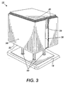
- Fig. 3 is a view otherwise identical to Fig. 2 but showing the relative positions of those same components after said initial loading, showing the conventional container box top removed and the top of the stack shown lifted up and slightly extending above the top of the open container for feeding sheets sequentially therefrom, while the remainder of the stack is still inside the container which is holding the stack in its properly stacked position (in both Figs. 2 and 3, optional edge markings on the edges of the sheets are also illustrated);
- Fig. 4 is a partially rear cross-sectional view of the embodiment of Fig. 1; and
- Fig. 5 schematically shows an example of an otherwise well known reproduction and sheet supply system containing three of the embodiments of Figs. 1-4, one of which is integral the printer one of which is in an attached modular additional high capacity sheet supply unit, and a third being used in a connecting on-line finisher unit as a removable sheet output stacker container for multiple printed and taped sheet sets.
-
- Referring to the Figures, there is shown in the disclosed embodiment a
system 10, by which an otherwise conventional reproduction apparatus (printer 20) can be directly loaded with a special container orbox 30, for improved loading and automatic feeding of a large stack ofcopy sheets 40 therefrom, with reduced operator effort, greater convenience, and improved stack registration control. This disclosed high capacitysheet feeding system 10 allows the copy sheets to be fed directly into thereproduction apparatus 20 for printing from a special supply container, such as 30, instead of requiring themachine 20 user or operator to manually unstack, unwrap and load plural reams of copy sheets into a conventional high capacity feeder. That is needed in order to provide a large (tall) stack of sheets sufficient to allow longer printing runs and/or larger print jobs without printing interruptions for reloading more copy sheets. For example, the particular exemplary sheet storage and transporting box or other container illustrated here can contain five or more reams of standard "4024" Xerox Corp. copy paper in a stack of about 25.4 cm (ten inches) high. Furthermore, manual sheet re-stacking errors (offset or skewed portions of a stack), which can lead to sheet feeding errors, are also avoided, because the stack remains within, and remains registered by, the four stack-confining side walls of thecontainer 30 except for a minor upper portion of thestack 40 which extends above the top edges of those side walls of the openedcontainer 30 for sheet feeding. - The disclosed high capacity
sheet feeding system 10 may be part of, and compatible with, an otherwise existing or conventional high capacitysheet feeding module 12, integral theprinter 20. Themodule 12, as is well known, may be integral to various reproduction machines or an add-on accessory thereto. Themodule 12 here conventionally provides atop sheet feeder 14 for thecopy sheet input 22 to aprinter 20. Thetop sheet feeder 14 of themodule 12 is overlying an otherwise conventionalsheet stacking input 16 comprising an otherwise conventional vertically repositionable elevator tray 18 (previously used as a loading shelf for stacking the copy sheet thereon, but not in this embodiment). - As shown for example in Fig. 4 (or the cited references), the
elevator tray 18 may be vertically elevated towards the paper feeder 14 (here, to lift and maintain the top of thestack 40 thereagainst withlifting rods 50, as will be described). Theelevator tray 18 may so moved by various known lift systems. Here thelift system 26 comprises by a motor and gear box driven lead screw and guides system, controlled in a known manner by acontroller 100. Connecting control sensors, as also shown in Fig. 4, may also be provided, and/or a pivoting or other engagement switch may be provided in thesheet feeder 14 itself. These controls act to stop the lifting movement of thelift system 26 once the top of thesheet stack 40 is moved up into engagement with thetop sheet feeder 14, and to restart and further lift up the top of thestack 40 as sheets are depleted therefrom by being fed off. - Fixed
alignment surfaces 24 or guide members are also provided as part of thestacking input 16 so that as a copysheets supply box 30 is inserted into thestacking input 16, thebox 30 is aligned on both axes. Thus, the insertedbox 30 is automatically correctly aligned under thesheet feeder 14, and is also aligned over the positions of the stack lifting rods 50 (to be described), whichrods 50 are preferably in fixed positions relative to theelevator tray 18, as shown, or integral therewith, or in a rod unit which replaces theelevator tray 18 and is connected to thelift system 26 instead of thetray 18. - Heretofore, the copy sheets for the
input 16 of thehigh cap module 12 would normally have had to have been manually unloaded from a prior paper supply container and unwrapped, one or more reams at time, and then manually placed onto theelevator tray 18, one or more reams at a time, neatly manually restacked in vertical alignment with one another, every time more copy sheets were needed at thatsheet supply input 16. That is, several manual unpacking, unwrapping, and restacking steps. Uneven restacking could result in missfeeding. - With the disclosed high capacity
sheet feeding system 10, the conventional highcap feeder module 12 may still conventional feed copy sheets sequentially from the top of a stack of sheets at thesheet input 16 with the existing, conventional,sheet feeder 14 to the connectingconventional printer 20sheet input 22, without any required modifications or additional cost. Yet, with the disclosed high capacitysheet feeding system 10, the highcap feeder module 12 can continuously feed, without interruptions, plural reams of copy paper, in a single stack ofcopy sheets 40, without operator intervention. In the disclosedsystem 10, the copy sheets feed directly from the copy sheet transporting and supply box orcontainer 30 to thesheet feeder 14 to feed theprinter 20, without any of the above-described manual unpacking, unwrapping, and restacking steps, as will be described. - Simply removing a box top (as shown in Fig. 2) from the copy
sheet supply box 30 and placing that openedbox 30 in thesheet input 16, as shown in Fig. 3 and Fig. 4, is the only operator manual operation required to load alarge stack 40 of copy sheets into theinput 16 of theprinter 20. Thebox 30 top may be conventional, as shown in Fig. 2. It may be simply lifted off, preferably after a strip of sealing tape around the edges of the box top is removed, as in a conventional paper supply box for xerographic copy paper. - The operator simply loads the full
paper supply box 30 into the stackinginput 16, overlying the tops of therods 50. In this embodiment of Fig. 4 the bottom 32 of thebox 30 may be loaded by sliding it onto a fixed U-shaped or other box bottom supportingsurface member 28. Theloading surface 28 is spaced above the lowest position of theelevator tray 18 by at least the length of therods 50 in this example, so that therods 50 do not interfere with the horizontal loading movement and lateral alignment of thebox 30. - The bottom 32 of the
box 30 itself has a plurality of holes, openings orapertures 34, here four of them, to allow the subsequent entry therethrough of a corresponding (or lesser) number oflift rods 50. As noted, therods 50 here are supported by or integral with the elevator tray orprior loading shelf 18 of the highcapacity feeder module 12, or otherwise connected to be lifted by thelift system 26. - Inside the
box 30, overlying theholes 34, is a rigid tray or false bottom 36 which is overlying, and initially resting on, the bottom 32 of the box, and is underlying all of the copy sheets in the box. That is, thestack 40 rests on, and is supported by, the tray orfalse bottom 36. - As the four
lift rods 50, all of the same height, are commonly lifted up together through theholes 34 in the bottom 32 of thebox 30 by thelift system 26, the tops of theselift rods 50 engage and lift this unapertured (at least in the same areas)false bottom 36 and thereby push up the entire stack of paper within thesupply box 30 up and out of the box and into engagement with the highcapacity stack feeder 14. Thefalse bottom 36 is loose in the bottom of thebox 30, by having somewhat smaller dimensions than the interior dimensions of thebox 30. - The
sheet feeder 14 is oriented above thebox 30 loading position in a position to feed the sheets directly from their initial stack orientation in the insertedsupply box 30. As the sheets feed out, the fourlift bars 50 automatically integrally move up to compensate for what would otherwise be a reduction in the stack height position relative to thefeeder 14, thus allowing thefeeder 14 to remain in substantially the same position, for feeding theentire stack 40. (As is well known, thefeeder 14 may be pivotal for partial adjustment to the level of the top of the stack from which it is feeding.) - The tray or false bottom 36 may also provide a seal for the
holes 34 in the bottom 32 of the stackingbox 30 before it is placed in use. The false bottom 36 may be, for example, heavy cardboard with a waterproof coating, or plastic, providing a sufficient seal to protect the paper inside the box before it is used. However, theholes 34 could also be covered on the outside or inside of the box bottom 32 with a tearable tape which could be sufficiently thin to be easily removed or ruptured automatically by the lift bars 50 penetrating through theholes 34. Thefalse bottom 36 is preferably a sufficiently thick and rigid cardboard or rigid plastic flat panel or the like that is strong enough to hold on top of it the weight of all of the paper and also stay relatively flat even though supported on only a "4-point suspension" on the tops of the fourlift rods 50. The tray or false bottom 36 may be of the same or different material as thebox 30 itself. It may be a simple planar sheet, or have bottom dimples or recesses engaged by the ends of therods 50, as shown in Fig. 4. - As one example, the stack lifting bars or
rods 50 would need to be only approximately 30 cm (12 inches) high for a box with an approximately 25 cm (ten inch) high stack, allowing approximately 5 cm (2 inches) for the travel and gradual lifting up of all of the paper in thebox 30, to empty thebox 30, as the top sheets are fed off the exposed top of thestack 40 by engagement with thesheet feeder 14. The number oflift rods 50 could, of course, be increased or decreased from the 4 shown here, if desired or necessary. Four rod ends provides stable vertical lifting with reasonably distributed forces, thus not requiring a particularly thick or strong stack supporting tray orfalse bottom 36. Therods 50 may be simple vertical rods of plastic or other suitable material, such as cylindrical or square tubes or channels on the order of approximately 2 cm (¾ inches) in diameter or greater, or even L or I beams of approximately those dimensions per side. - Various other alternative elevator and elevator tray mechanisms known to existing high capacity feeder trays, or copy sheet output trays, can be utilized with the
lift rods 50 or other versions thereof, and need not be described herein. For example, as an alternative to what is shown here, the elevator mechanism could connect only with therods 50, and a fixed position butapertured box 30 loading surface member could be provided, such that in their lowest position the tops of therods 50 could be approximately flush with that generally horizontal loading surface on which thesupply box 30 is loaded. Therods 50 would then elevate up through the apertures in the loading surface and the box bottom 32 resting thereon to engage thestack supporting tray 36 within thebox 30. In another alternative therods 50 can be integral theelevatable loading shelf 18 rather than being mounted to a base plate as a separate unit which is mounted on thatshelf 18, as shown. - In another alternative, a dual mode high cap feeder can be provided, so that it can be used with or without the disclosed special supply box. The elevator tray under the box can be conventionally designed to unhook or unlatch from the elevator posts if the special supply box is present, or be latched to the posts to hold, lift and feed a manually loaded stack of paper thereon without the special box.
- As noted above, lead-in guides or baffles 24 in the
module 12 can be provided to ensure that thebox 30 is properly positioned and aligned within thecopy sheet input 16 with the box holes 34 aligned over the tops of thelift rods 50, thereby ensuring that therods 50 are in position to move up through thoseholes 34 in the bottom of the box to engage the tray or false bottom 36, as particularly shown in Fig. 4. Theholes 34 may of course be substantially larger in diameter than the diameter of thelift rods 50, to provide non-critical alignment. - Furthermore, the copy
paper supply boxes 30 can be reusable. When a copysheet supply box 30 is (automatically) emptied, as described herein, it can be used at the output end of theprinter 20, as shown in Fig. 5, as a output stacker and transport container for the finished printed sheet sets. - The
box 30 may also be provided as shown with avertical viewing window 38 in a side wall of thebox 30 which allows the operator to view the level of paper remaining to be fed before another reloading operation is required. When abox 30 is being alternatively used as a output stacker, the samevertical viewing window 38 can then allow the operator to view the level or fullness of the stack within the box. Thetransparent window 38 may be provided by a Mylar™ or other clear plastic strip sealed to each side of the window slot in the side of thebox 30. Thisviewing window 38 may have a removable tape protective cover which can be removed when thebox 30 is to be used. - It will be appreciated from this teaching that various alternatives, modifications, variations or improvements therein may be made by those skilled in the art, which are intended to be encompassed by the following claims.
Claims (9)
- A high capacity copy sheet supplying system (10) for a reproduction apparatus, with a sheet feeder (14) for feeding copy sheets into said reproduction apparatus, and with a sheet supply input (16) into which a multi-ream stack (40) of a large number of copy sheets may be loaded, and with an elevator system (26) for lifting the stack of copy sheets in said sheet supply input into sheet feeding engagement between the top of said stack and said sheet feeder, and for maintaining the top of said stack in said sheet feeding engagement with said sheet feeder as said stack is depleted by said feeding of said copy sheets by said sheet feeder into said reproduction apparatus, the system comprising:a sheet stack shipping container (30) insertable into said sheet supply input of said high capacity sheet supplying system,said sheet stack shipping container having sheet stack confining side walls and a bottom wall (32), anda false bottom tray insert (36) loosely overlying said bottom wall of said sheet stack shipping container (30),said multi-ream stack (40) of copy sheets being supported on said false bottom tray insert in said sheet stack shipping container;said high capacity copy sheet supplying system being characterized byplural spaced apart lift rods (50) operatively connecting with said elevator mechanism for substantially vertical movement,said lift rods (50) being respectively spaced in alignment with respect to plural spaced apertures in said bottom wall of said sheet supplying container (30),said lift rods (50) extending substantially parallel to one another and having rod ends in substantially the same plane,said lift rods (50) extending longer than said sheet stack confining side walls, andsaid plurality of spaced apart lift rods (50) being movable by said elevator system (26) to extend up through said plural spaced apertures in said bottom wall (32) of said sheet stack shipping container to engage and lift said false bottom tray insert (36) and said multi-ream stack (40) of copy sheets supported thereon by lifting engagement of said rod ends of said lift rods with said false bottom tray insert, so as to vertically lift said multi-ream stack (40) of copy sheets relative to said sheet stack shipping container above said sheet stack confining side walls and into engagement with said sheet feeder (14).
- The high capacity copy sheet supplying system of claim 1, wherein said sheet supply input (16) includes a supporting surface (28) for said sheet stack shipping container and an input alignment system (24) for said sheet stack shipping container for aligning said plural spaced apertures in said sheet stack shipping container with said plural spaced apart lift rods (50).
- The high capacity copy sheet supplying system of claim 1, wherein said sheet supplying container (30) has at least one said side wall with a vertical transparent window (38) through which the height of said stack of copy sheets in said sheet supplying container is visible from outside of said sheet stack shipping container.
- The high capacity copy sheet supplying system of claim 1, wherein said plural spaced lift rods (50) comprises four such rods.
- The high capacity copy sheet supplying system of claim 1, wherein said elevator system (26) includes a sheet stacking elevator tray (18) for manually stacking sheets thereon for feeding said sheets with said sheet feeder (14) without said sheet stack shipping container.
- The high capacity copy sheet supplying system of claim 1, wherein said sheet stack shipping container is a reusable container adapted to be alternatively placed at the output of a reproduction apparatus for the stacking therein of printed sheets outputted by said reproduction apparatus.
- The high capacity copy sheet supplying system of claim 6, wherein said sheet stack shipping container has at least one said side wall with a vertical transparent window (38) through which the edges of printed sheets in said sheet stack shipping container are visible from outside of said sheet stack shipping container.
- A method of loading a multi-ream stack (40) of printing sheets into a high capacity printing sheets feeding input (16) of a printer and maintaining the top of said multi-ream stack of printing sheets in sheet feeding engagement with a sheet feeder (14) for feeding said sheets to said printer, comprising:unsealing and inserting a sealed sheet stack shipping container (30) holding said multi-ream stack of printing sheets therein into said printing sheets feeding input (16) of said printer without unloading said sheets from said container, said container having an apertured bottom and a false bottom tray insert (36),supporting said multi-ream stack (40) of printing sheets in said container on said false bottom tray insert (36), said false bottom tray insert being inside of said sheet stack shipping container and overlying said multi-apertured bottom (32) of said sheet stack shipping container, andlifting and maintaining the top of said multi-ream stack of printing sheets in said sheet stack shipping container in engagement with said sheet feeder (14) with an automatic lifting system (26), characterized in that said automatic lifting system (26) comprises an elevator system operatively engaging a plurality of spaced apart elongated lifting rods (50) inserted through at least some of apertures in said multi-apertured bottom (32) of said sheet stack shipping container, said lifting system engaging, supporting, and lifting said false bottom tray insert (36) to lift at least a portion of said multi-ream stack (40) of printing sheets supported thereon up above said sheet stack shipping container for said engagement with said sheet feeder.
- The method of claim 8, further including maintaining said top of said tall stack (40) of printing sheets at a level extending slightly above the top of said sheet stack sheet stack shipping container (30) by said lifting as said sheets are fed by said sheet feeder (14) to said printer.
Applications Claiming Priority (2)
| Application Number | Priority Date | Filing Date | Title |
|---|---|---|---|
| US442661 | 1999-11-18 | ||
| US09/442,661 US6286827B1 (en) | 1999-11-18 | 1999-11-18 | High capacity automatic sheet input system for a reproduction apparatus |
Publications (3)
| Publication Number | Publication Date |
|---|---|
| EP1101718A2 EP1101718A2 (en) | 2001-05-23 |
| EP1101718A3 EP1101718A3 (en) | 2002-04-03 |
| EP1101718B1 true EP1101718B1 (en) | 2004-05-12 |
Family
ID=23757638
Family Applications (1)
| Application Number | Title | Priority Date | Filing Date |
|---|---|---|---|
| EP00124823A Expired - Lifetime EP1101718B1 (en) | 1999-11-18 | 2000-11-14 | High capacity automatic sheet input system for a reproduction apparatus |
Country Status (4)
| Country | Link |
|---|---|
| US (1) | US6286827B1 (en) |
| EP (1) | EP1101718B1 (en) |
| JP (1) | JP4851001B2 (en) |
| DE (1) | DE60010623T2 (en) |
Families Citing this family (19)
| Publication number | Priority date | Publication date | Assignee | Title |
|---|---|---|---|---|
| US7025346B1 (en) * | 1999-06-07 | 2006-04-11 | Hewlett-Packard Development Company, L.P. | System and related methods for automatically determining the media count in a printing device media tray |
| US6698747B2 (en) * | 2001-02-06 | 2004-03-02 | Heidelberger Druckmaschinen Ag | Method and system for providing sheet stack level control |
| US6884392B2 (en) * | 2002-11-12 | 2005-04-26 | Minntech Corporation | Apparatus and method for steam reprocessing flexible endoscopes |
| US6806946B2 (en) * | 2002-12-17 | 2004-10-19 | Kabushiki Kaisha Toshiba | Feed paper apparatus |
| US6945527B2 (en) * | 2003-02-28 | 2005-09-20 | Hewlett-Packard Development Company, L.P. | High capacity media apparatus and method |
| JP4720628B2 (en) * | 2006-06-06 | 2011-07-13 | 富士ゼロックス株式会社 | Paper feeder |
| DE202006010327U1 (en) * | 2006-07-04 | 2007-11-15 | Prometal Rct Gmbh | Swap bodies |
| DE102006031120B3 (en) * | 2006-07-05 | 2008-03-06 | Siemens Ag | mail containers |
| JP4772633B2 (en) * | 2006-09-28 | 2011-09-14 | 京セラミタ株式会社 | Paper feeder |
| US7533879B2 (en) * | 2007-09-18 | 2009-05-19 | Xerox Corporation | Variable frequency tampers for coated stocks used in paper feed trays |
| US7918444B2 (en) * | 2008-07-11 | 2011-04-05 | Lexmark International, Inc. | Media handling device having media shingling mechanism for providing uniform inter-page gap between successive media sheets |
| US9427928B2 (en) * | 2009-08-25 | 2016-08-30 | Sealed Air Corporation (Us) | Method and machine for producing packaging cushioning |
| US8348818B2 (en) | 2010-05-27 | 2013-01-08 | Sealed Air Corporation (Us) | Machine for producing packaging cushioning |
| WO2012154163A1 (en) * | 2011-05-07 | 2012-11-15 | King Saud University | Large capacity automatic paper tray |
| JP2013006653A (en) * | 2011-06-23 | 2013-01-10 | Fuji Xerox Co Ltd | Recording material feeder and image forming device |
| KR101915774B1 (en) | 2017-04-19 | 2018-11-06 | 주식회사 엠에프에스코퍼레이션 | cash cassette of banking system |
| JP2022006403A (en) | 2020-06-24 | 2022-01-13 | ブラザー工業株式会社 | Image recording device |
| JP2022006402A (en) * | 2020-06-24 | 2022-01-13 | ブラザー工業株式会社 | Image recording device |
| KR102324466B1 (en) * | 2020-09-21 | 2021-11-11 | 주식회사 에스디텍 | Automatic paper feeder |
Family Cites Families (22)
| Publication number | Priority date | Publication date | Assignee | Title |
|---|---|---|---|---|
| JPS4926847B1 (en) * | 1969-10-22 | 1974-07-12 | ||
| US4504053A (en) * | 1981-02-19 | 1985-03-12 | Konishiroku Photo Industry Co., Ltd. | Paper feeding means for recording apparatus |
| JPS586845A (en) | 1981-06-30 | 1983-01-14 | Minolta Camera Co Ltd | Recording apparatus |
| US4750729A (en) * | 1983-06-10 | 1988-06-14 | Canon Kabushiki Kaisha | Sheet loading device |
| JPS6077861A (en) * | 1983-09-27 | 1985-05-02 | キヤノン株式会社 | Container |
| US4556210A (en) | 1983-12-21 | 1985-12-03 | Xerox Corporation | High speed duplicator with copy sheet pre-loading receptacle |
| US4802586A (en) | 1984-09-27 | 1989-02-07 | Xerox Corporation | High speed duplicator with copy sheet prepackaged shipping and loading carton |
| US4770301A (en) | 1984-09-27 | 1988-09-13 | Xerox Corporation | High speed duplicator with copy sheet prepackaged shipping and loading carton |
| US4718658A (en) | 1986-02-27 | 1988-01-12 | Nippon Seimitsu Kogyo Kabushiki Kaisha | Sheet feeding system using detachable sheet storage unit in image processing device |
| GB8611792D0 (en) * | 1986-05-14 | 1986-06-25 | Xerox Corp | Sheet feed apparatus & cartridge |
| US4946157A (en) * | 1988-09-12 | 1990-08-07 | Gunther International, Ltd. | Sheet loading and unloading mechanism |
| DE4004417A1 (en) * | 1989-02-17 | 1990-08-23 | Minolta Camera Kk | Sheet cassette for laser primer - has photosensitive sheets prevented from exposure by cover rolled back during loading |
| US5152520A (en) | 1990-12-20 | 1992-10-06 | Xerox Corporation | Universal non-dedicated high capacity feeder |
| CH683089A5 (en) * | 1991-06-19 | 1994-01-14 | Oscar Roth | The set of parts for producing a package. |
| GB2259500B (en) | 1991-09-11 | 1995-07-12 | Xerox Corp | Sheet feed apparatus |
| CA2079356A1 (en) | 1991-12-16 | 1993-06-17 | Murray O. Meetze | Removable set retaining system for copy sheets |
| EP0547788B1 (en) | 1991-12-16 | 1996-10-16 | Xerox Corporation | Removable set retaining system for copy sheets |
| US5222860A (en) * | 1992-06-25 | 1993-06-29 | Xerox Corporation | Floor space efficient printer with high load and unload capability |
| US5219158A (en) * | 1992-09-28 | 1993-06-15 | Xerox Corporation | Two corner sheet stacking apparatus with matching cover |
| JPH10203656A (en) * | 1997-01-20 | 1998-08-04 | Ricoh Co Ltd | Recycle case for transfer paper and paper feed tray structure |
| JPH1179425A (en) * | 1997-09-08 | 1999-03-23 | Ricoh Co Ltd | Paper feeder |
| JPH11301860A (en) * | 1998-04-17 | 1999-11-02 | Ricoh Co Ltd | Paper feeder |
-
1999
- 1999-11-18 US US09/442,661 patent/US6286827B1/en not_active Expired - Lifetime
-
2000
- 2000-11-09 JP JP2000342294A patent/JP4851001B2/en not_active Expired - Fee Related
- 2000-11-14 DE DE60010623T patent/DE60010623T2/en not_active Expired - Lifetime
- 2000-11-14 EP EP00124823A patent/EP1101718B1/en not_active Expired - Lifetime
Also Published As
| Publication number | Publication date |
|---|---|
| DE60010623T2 (en) | 2004-09-23 |
| EP1101718A2 (en) | 2001-05-23 |
| JP4851001B2 (en) | 2012-01-11 |
| US6286827B1 (en) | 2001-09-11 |
| JP2001146324A (en) | 2001-05-29 |
| DE60010623D1 (en) | 2004-06-17 |
| EP1101718A3 (en) | 2002-04-03 |
Similar Documents
| Publication | Publication Date | Title |
|---|---|---|
| EP1101718B1 (en) | High capacity automatic sheet input system for a reproduction apparatus | |
| KR100490079B1 (en) | Sheet containing apparatus, sheet feeding apparatus provided with the same, and image forming apparatus | |
| EP1767476A2 (en) | Sheet conveying apparatus, image recording apparatus and image reading apparatus | |
| EP1295824B1 (en) | Sheet containing device and sheet feeder having the same, and image forming apparatus | |
| EP0246067B1 (en) | Sheet feed apparatus and cartridge therefor | |
| JP4410434B2 (en) | Paper feeder and image forming device | |
| US5150893A (en) | Paper feed mechanism with plural support tables for supplying cut sheets to a printing apparatus | |
| US8424862B2 (en) | Composite substrate feeding mechanism | |
| JP3391844B2 (en) | Sheet handling system for printer | |
| US5915687A (en) | Printer high capacity output stacker documents removal system | |
| US5328167A (en) | Sheet feed apparatus | |
| JP2774670B2 (en) | Paper feeder for printing press | |
| US20040094886A1 (en) | Media handling device and methods | |
| KR20010052700A (en) | Tray for narrow and normal width sheets | |
| JPH0692486A (en) | Paper feeding device | |
| US6065745A (en) | Cradle for feeding of non-uniform sheets in a printer or copier | |
| JPH09194047A (en) | Tray for mass paper feeder | |
| US7967286B2 (en) | Sheet stacking tray assembly with geometric protuberances | |
| JP2001261167A (en) | Paper feeding device | |
| JPH0733265A (en) | Mass paper feeder | |
| JPS62205932A (en) | Paper feed cassette | |
| US20030188985A1 (en) | Plate cassette for platesetter | |
| JPH03192029A (en) | Sheet material loading device | |
| JPH05193759A (en) | Large quantity of paper sheet feeding device of image forming device | |
| JPH05193755A (en) | Paper sheet feeding device of image forming device containing a plurality of paper sheet pack |
Legal Events
| Date | Code | Title | Description |
|---|---|---|---|
| PUAI | Public reference made under article 153(3) epc to a published international application that has entered the european phase |
Free format text: ORIGINAL CODE: 0009012 |
|
| AK | Designated contracting states |
Kind code of ref document: A2 Designated state(s): DE FR GB Kind code of ref document: A2 Designated state(s): AT BE CH CY DE DK ES FI FR GB GR IE IT LI LU MC NL PT SE TR |
|
| AX | Request for extension of the european patent |
Free format text: AL;LT;LV;MK;RO;SI |
|
| PUAL | Search report despatched |
Free format text: ORIGINAL CODE: 0009013 |
|
| AK | Designated contracting states |
Kind code of ref document: A3 Designated state(s): AT BE CH CY DE DK ES FI FR GB GR IE IT LI LU MC NL PT SE TR |
|
| AX | Request for extension of the european patent |
Free format text: AL;LT;LV;MK;RO;SI |
|
| RIC1 | Information provided on ipc code assigned before grant |
Free format text: 7B 65H 1/26 A, 7B 65H 1/14 B, 7B 65H 1/04 B, 7B 65H 1/08 B |
|
| 17P | Request for examination filed |
Effective date: 20021004 |
|
| AKX | Designation fees paid |
Free format text: DE FR GB |
|
| 17Q | First examination report despatched |
Effective date: 20030513 |
|
| GRAP | Despatch of communication of intention to grant a patent |
Free format text: ORIGINAL CODE: EPIDOSNIGR1 |
|
| GRAS | Grant fee paid |
Free format text: ORIGINAL CODE: EPIDOSNIGR3 |
|
| GRAA | (expected) grant |
Free format text: ORIGINAL CODE: 0009210 |
|
| AK | Designated contracting states |
Kind code of ref document: B1 Designated state(s): DE FR GB |
|
| REG | Reference to a national code |
Ref country code: GB Ref legal event code: FG4D |
|
| REG | Reference to a national code |
Ref country code: IE Ref legal event code: FG4D |
|
| REF | Corresponds to: |
Ref document number: 60010623 Country of ref document: DE Date of ref document: 20040617 Kind code of ref document: P |
|
| ET | Fr: translation filed | ||
| PLBE | No opposition filed within time limit |
Free format text: ORIGINAL CODE: 0009261 |
|
| STAA | Information on the status of an ep patent application or granted ep patent |
Free format text: STATUS: NO OPPOSITION FILED WITHIN TIME LIMIT |
|
| 26N | No opposition filed |
Effective date: 20050215 |
|
| REG | Reference to a national code |
Ref country code: GB Ref legal event code: 746 Effective date: 20050809 |
|
| REG | Reference to a national code |
Ref country code: FR Ref legal event code: PLFP Year of fee payment: 16 |
|
| REG | Reference to a national code |
Ref country code: FR Ref legal event code: PLFP Year of fee payment: 17 |
|
| PGFP | Annual fee paid to national office [announced via postgrant information from national office to epo] |
Ref country code: GB Payment date: 20161027 Year of fee payment: 17 Ref country code: DE Payment date: 20161020 Year of fee payment: 17 Ref country code: FR Payment date: 20161024 Year of fee payment: 17 |
|
| REG | Reference to a national code |
Ref country code: DE Ref legal event code: R119 Ref document number: 60010623 Country of ref document: DE |
|
| GBPC | Gb: european patent ceased through non-payment of renewal fee |
Effective date: 20171114 |
|
| REG | Reference to a national code |
Ref country code: FR Ref legal event code: ST Effective date: 20180731 |
|
| PG25 | Lapsed in a contracting state [announced via postgrant information from national office to epo] |
Ref country code: FR Free format text: LAPSE BECAUSE OF NON-PAYMENT OF DUE FEES Effective date: 20171130 Ref country code: DE Free format text: LAPSE BECAUSE OF NON-PAYMENT OF DUE FEES Effective date: 20180602 |
|
| PG25 | Lapsed in a contracting state [announced via postgrant information from national office to epo] |
Ref country code: GB Free format text: LAPSE BECAUSE OF NON-PAYMENT OF DUE FEES Effective date: 20171114 |