EP1101644A2 - Low floor drive unit assembly for an electrically driven vehicle - Google Patents
Low floor drive unit assembly for an electrically driven vehicle Download PDFInfo
- Publication number
- EP1101644A2 EP1101644A2 EP01102768A EP01102768A EP1101644A2 EP 1101644 A2 EP1101644 A2 EP 1101644A2 EP 01102768 A EP01102768 A EP 01102768A EP 01102768 A EP01102768 A EP 01102768A EP 1101644 A2 EP1101644 A2 EP 1101644A2
- Authority
- EP
- European Patent Office
- Prior art keywords
- gear
- assembly
- rotation
- driving
- electric motor
- Prior art date
- Legal status (The legal status is an assumption and is not a legal conclusion. Google has not performed a legal analysis and makes no representation as to the accuracy of the status listed.)
- Granted
Links
- 230000009467 reduction Effects 0.000 claims abstract description 3
- 239000000725 suspension Substances 0.000 description 32
- 230000008878 coupling Effects 0.000 description 16
- 238000010168 coupling process Methods 0.000 description 16
- 238000005859 coupling reaction Methods 0.000 description 16
- 230000000712 assembly Effects 0.000 description 4
- 238000000429 assembly Methods 0.000 description 4
- 230000008901 benefit Effects 0.000 description 4
- 238000004806 packaging method and process Methods 0.000 description 4
- 238000000034 method Methods 0.000 description 3
- 230000005540 biological transmission Effects 0.000 description 2
- 230000004044 response Effects 0.000 description 2
- 241000239290 Araneae Species 0.000 description 1
- 230000001133 acceleration Effects 0.000 description 1
- 230000007423 decrease Effects 0.000 description 1
- 238000009459 flexible packaging Methods 0.000 description 1
- 239000000463 material Substances 0.000 description 1
- 238000012986 modification Methods 0.000 description 1
- 230000004048 modification Effects 0.000 description 1
Images


Classifications
-
- B—PERFORMING OPERATIONS; TRANSPORTING
- B60—VEHICLES IN GENERAL
- B60K—ARRANGEMENT OR MOUNTING OF PROPULSION UNITS OR OF TRANSMISSIONS IN VEHICLES; ARRANGEMENT OR MOUNTING OF PLURAL DIVERSE PRIME-MOVERS IN VEHICLES; AUXILIARY DRIVES FOR VEHICLES; INSTRUMENTATION OR DASHBOARDS FOR VEHICLES; ARRANGEMENTS IN CONNECTION WITH COOLING, AIR INTAKE, GAS EXHAUST OR FUEL SUPPLY OF PROPULSION UNITS IN VEHICLES
- B60K7/00—Disposition of motor in, or adjacent to, traction wheel
- B60K7/0007—Disposition of motor in, or adjacent to, traction wheel the motor being electric
-
- B—PERFORMING OPERATIONS; TRANSPORTING
- B60—VEHICLES IN GENERAL
- B60K—ARRANGEMENT OR MOUNTING OF PROPULSION UNITS OR OF TRANSMISSIONS IN VEHICLES; ARRANGEMENT OR MOUNTING OF PLURAL DIVERSE PRIME-MOVERS IN VEHICLES; AUXILIARY DRIVES FOR VEHICLES; INSTRUMENTATION OR DASHBOARDS FOR VEHICLES; ARRANGEMENTS IN CONNECTION WITH COOLING, AIR INTAKE, GAS EXHAUST OR FUEL SUPPLY OF PROPULSION UNITS IN VEHICLES
- B60K1/00—Arrangement or mounting of electrical propulsion units
- B60K1/02—Arrangement or mounting of electrical propulsion units comprising more than one electric motor
-
- B—PERFORMING OPERATIONS; TRANSPORTING
- B60—VEHICLES IN GENERAL
- B60K—ARRANGEMENT OR MOUNTING OF PROPULSION UNITS OR OF TRANSMISSIONS IN VEHICLES; ARRANGEMENT OR MOUNTING OF PLURAL DIVERSE PRIME-MOVERS IN VEHICLES; AUXILIARY DRIVES FOR VEHICLES; INSTRUMENTATION OR DASHBOARDS FOR VEHICLES; ARRANGEMENTS IN CONNECTION WITH COOLING, AIR INTAKE, GAS EXHAUST OR FUEL SUPPLY OF PROPULSION UNITS IN VEHICLES
- B60K17/00—Arrangement or mounting of transmissions in vehicles
- B60K17/04—Arrangement or mounting of transmissions in vehicles characterised by arrangement, location or kind of gearing
- B60K17/043—Transmission unit disposed in on near the vehicle wheel, or between the differential gear unit and the wheel
- B60K17/046—Transmission unit disposed in on near the vehicle wheel, or between the differential gear unit and the wheel with planetary gearing having orbital motion
-
- B—PERFORMING OPERATIONS; TRANSPORTING
- B60—VEHICLES IN GENERAL
- B60K—ARRANGEMENT OR MOUNTING OF PROPULSION UNITS OR OF TRANSMISSIONS IN VEHICLES; ARRANGEMENT OR MOUNTING OF PLURAL DIVERSE PRIME-MOVERS IN VEHICLES; AUXILIARY DRIVES FOR VEHICLES; INSTRUMENTATION OR DASHBOARDS FOR VEHICLES; ARRANGEMENTS IN CONNECTION WITH COOLING, AIR INTAKE, GAS EXHAUST OR FUEL SUPPLY OF PROPULSION UNITS IN VEHICLES
- B60K17/00—Arrangement or mounting of transmissions in vehicles
- B60K17/22—Arrangement or mounting of transmissions in vehicles characterised by arrangement, location, or type of main drive shafting, e.g. cardan shaft
-
- B—PERFORMING OPERATIONS; TRANSPORTING
- B60—VEHICLES IN GENERAL
- B60G—VEHICLE SUSPENSION ARRANGEMENTS
- B60G2204/00—Indexing codes related to suspensions per se or to auxiliary parts
- B60G2204/10—Mounting of suspension elements
- B60G2204/30—In-wheel mountings
-
- B—PERFORMING OPERATIONS; TRANSPORTING
- B60—VEHICLES IN GENERAL
- B60K—ARRANGEMENT OR MOUNTING OF PROPULSION UNITS OR OF TRANSMISSIONS IN VEHICLES; ARRANGEMENT OR MOUNTING OF PLURAL DIVERSE PRIME-MOVERS IN VEHICLES; AUXILIARY DRIVES FOR VEHICLES; INSTRUMENTATION OR DASHBOARDS FOR VEHICLES; ARRANGEMENTS IN CONNECTION WITH COOLING, AIR INTAKE, GAS EXHAUST OR FUEL SUPPLY OF PROPULSION UNITS IN VEHICLES
- B60K17/00—Arrangement or mounting of transmissions in vehicles
- B60K17/04—Arrangement or mounting of transmissions in vehicles characterised by arrangement, location or kind of gearing
- B60K17/043—Transmission unit disposed in on near the vehicle wheel, or between the differential gear unit and the wheel
-
- B—PERFORMING OPERATIONS; TRANSPORTING
- B60—VEHICLES IN GENERAL
- B60K—ARRANGEMENT OR MOUNTING OF PROPULSION UNITS OR OF TRANSMISSIONS IN VEHICLES; ARRANGEMENT OR MOUNTING OF PLURAL DIVERSE PRIME-MOVERS IN VEHICLES; AUXILIARY DRIVES FOR VEHICLES; INSTRUMENTATION OR DASHBOARDS FOR VEHICLES; ARRANGEMENTS IN CONNECTION WITH COOLING, AIR INTAKE, GAS EXHAUST OR FUEL SUPPLY OF PROPULSION UNITS IN VEHICLES
- B60K7/00—Disposition of motor in, or adjacent to, traction wheel
- B60K2007/003—Disposition of motor in, or adjacent to, traction wheel with two or more motors driving a single wheel
-
- B—PERFORMING OPERATIONS; TRANSPORTING
- B60—VEHICLES IN GENERAL
- B60K—ARRANGEMENT OR MOUNTING OF PROPULSION UNITS OR OF TRANSMISSIONS IN VEHICLES; ARRANGEMENT OR MOUNTING OF PLURAL DIVERSE PRIME-MOVERS IN VEHICLES; AUXILIARY DRIVES FOR VEHICLES; INSTRUMENTATION OR DASHBOARDS FOR VEHICLES; ARRANGEMENTS IN CONNECTION WITH COOLING, AIR INTAKE, GAS EXHAUST OR FUEL SUPPLY OF PROPULSION UNITS IN VEHICLES
- B60K7/00—Disposition of motor in, or adjacent to, traction wheel
- B60K2007/0038—Disposition of motor in, or adjacent to, traction wheel the motor moving together with the wheel axle
-
- B—PERFORMING OPERATIONS; TRANSPORTING
- B60—VEHICLES IN GENERAL
- B60K—ARRANGEMENT OR MOUNTING OF PROPULSION UNITS OR OF TRANSMISSIONS IN VEHICLES; ARRANGEMENT OR MOUNTING OF PLURAL DIVERSE PRIME-MOVERS IN VEHICLES; AUXILIARY DRIVES FOR VEHICLES; INSTRUMENTATION OR DASHBOARDS FOR VEHICLES; ARRANGEMENTS IN CONNECTION WITH COOLING, AIR INTAKE, GAS EXHAUST OR FUEL SUPPLY OF PROPULSION UNITS IN VEHICLES
- B60K7/00—Disposition of motor in, or adjacent to, traction wheel
- B60K2007/0069—Disposition of motor in, or adjacent to, traction wheel the motor axle being perpendicular to the wheel axle
- B60K2007/0076—Disposition of motor in, or adjacent to, traction wheel the motor axle being perpendicular to the wheel axle the motor axle being horizontal
-
- B—PERFORMING OPERATIONS; TRANSPORTING
- B60—VEHICLES IN GENERAL
- B60K—ARRANGEMENT OR MOUNTING OF PROPULSION UNITS OR OF TRANSMISSIONS IN VEHICLES; ARRANGEMENT OR MOUNTING OF PLURAL DIVERSE PRIME-MOVERS IN VEHICLES; AUXILIARY DRIVES FOR VEHICLES; INSTRUMENTATION OR DASHBOARDS FOR VEHICLES; ARRANGEMENTS IN CONNECTION WITH COOLING, AIR INTAKE, GAS EXHAUST OR FUEL SUPPLY OF PROPULSION UNITS IN VEHICLES
- B60K7/00—Disposition of motor in, or adjacent to, traction wheel
- B60K2007/0069—Disposition of motor in, or adjacent to, traction wheel the motor axle being perpendicular to the wheel axle
- B60K2007/0084—Disposition of motor in, or adjacent to, traction wheel the motor axle being perpendicular to the wheel axle the motor axle being vertical
-
- B—PERFORMING OPERATIONS; TRANSPORTING
- B60—VEHICLES IN GENERAL
- B60L—PROPULSION OF ELECTRICALLY-PROPELLED VEHICLES; SUPPLYING ELECTRIC POWER FOR AUXILIARY EQUIPMENT OF ELECTRICALLY-PROPELLED VEHICLES; ELECTRODYNAMIC BRAKE SYSTEMS FOR VEHICLES IN GENERAL; MAGNETIC SUSPENSION OR LEVITATION FOR VEHICLES; MONITORING OPERATING VARIABLES OF ELECTRICALLY-PROPELLED VEHICLES; ELECTRIC SAFETY DEVICES FOR ELECTRICALLY-PROPELLED VEHICLES
- B60L2200/00—Type of vehicles
- B60L2200/18—Buses
-
- B—PERFORMING OPERATIONS; TRANSPORTING
- B60—VEHICLES IN GENERAL
- B60L—PROPULSION OF ELECTRICALLY-PROPELLED VEHICLES; SUPPLYING ELECTRIC POWER FOR AUXILIARY EQUIPMENT OF ELECTRICALLY-PROPELLED VEHICLES; ELECTRODYNAMIC BRAKE SYSTEMS FOR VEHICLES IN GENERAL; MAGNETIC SUSPENSION OR LEVITATION FOR VEHICLES; MONITORING OPERATING VARIABLES OF ELECTRICALLY-PROPELLED VEHICLES; ELECTRIC SAFETY DEVICES FOR ELECTRICALLY-PROPELLED VEHICLES
- B60L2200/00—Type of vehicles
- B60L2200/30—Trolleys
-
- B—PERFORMING OPERATIONS; TRANSPORTING
- B60—VEHICLES IN GENERAL
- B60L—PROPULSION OF ELECTRICALLY-PROPELLED VEHICLES; SUPPLYING ELECTRIC POWER FOR AUXILIARY EQUIPMENT OF ELECTRICALLY-PROPELLED VEHICLES; ELECTRODYNAMIC BRAKE SYSTEMS FOR VEHICLES IN GENERAL; MAGNETIC SUSPENSION OR LEVITATION FOR VEHICLES; MONITORING OPERATING VARIABLES OF ELECTRICALLY-PROPELLED VEHICLES; ELECTRIC SAFETY DEVICES FOR ELECTRICALLY-PROPELLED VEHICLES
- B60L2220/00—Electrical machine types; Structures or applications thereof
- B60L2220/40—Electrical machine applications
- B60L2220/46—Wheel motors, i.e. motor connected to only one wheel
-
- B—PERFORMING OPERATIONS; TRANSPORTING
- B60—VEHICLES IN GENERAL
- B60Y—INDEXING SCHEME RELATING TO ASPECTS CROSS-CUTTING VEHICLE TECHNOLOGY
- B60Y2200/00—Type of vehicle
- B60Y2200/10—Road Vehicles
- B60Y2200/14—Trucks; Load vehicles, Busses
- B60Y2200/143—Busses
- B60Y2200/1432—Low floor busses
Definitions
- This invention relates to a unique drive arrangement for electrically driving the wheels of a vehicle in such a way that the floor of the vehicle may be lower than was the case in the prior art.
- Mass transit vehicles such as a bus or trolley car, typically have seats aligned at the lateral sides of the vehicle, with a central aisle extending along the vehicle.
- the seats are typically at a higher vertical location than the aisle, and thus cover the wheels. It would be desirable to have the aisle positioned relatively low to the ground. This would provide increased passenger space within the body of the vehicle, and may allow the designer to reduce the overall height of the mass transit vehicle.
- Other advantages to having a lower floor position include improved handicapped access and greater ease in the loading and unloading of passengers.
- Mass transit vehicles typically have several axles which support and drive or steer the vehicle. If the axle is a driving axle, then electric motors can be used to generate torque to drive the wheels. In a typical configuration, a centrally located electric motor drives two opposed wheels at the sides of the vehicle by way of a conventional axle. Usually, transmissions or drive shafts extend from the central motor to the axle.
- the subject invention relates to an automotive vehicle drive unit assembly which includes a first driving axle and a second driving axle which together define an axis of rotation.
- the drive unit assembly further includes a first wheel hub and a second wheel hub which are driven about the axis of rotation.
- a first gear set drives the first wheel hub and a second gear set drives the second wheel hub.
- a first electric motor is mounted at an angle relative to the axis of rotation of the first driving axle and drives the first gear set
- a second electric motor is mounted at an angle relative to the axis of rotation of the second driving axle and drives the second gear set.
- the relatively heavy electric motors are supported on vehicle suspension beams.
- the present invention does not require any extra mounting or attachment structure.
- the suspension beam is a relatively strong item, and is able to adequately support the motors.
- the suspension beam interconnects the wheel axle housing, brake assemblies, etc. to air springs and is subject to twisting and bumping due to road inputs.
- the structural integrity of the electric motor is maintained by the use of a flexible coupling between the gear box and the electric motor and a movable connection between the electric motor and the suspension beam.
- the flexible coupling and movable connection allow the electric motor to pivot and move as the suspension beam flexes and twists in response to vehicle weight and road load inputs.
- a bevel gear drive connection between the motor and a wheel hub is arranged to conserve and optimize space adjacent the wheel.
- the bevel gear is mounted on one side of the axis of rotation and the motor is mounted on the other. In this way, undue space is not required for the motor on either side of the wheel axis.
- the motor is mounted to an open side of a gear housing.
- the gear housing may be associated with the axle housing for the vehicle.
- the motor is bolted to the gear housing, and closes the opening.
- a bevel gear is mounted in the gear housing at an opposed side of the axis of rotation from the motor.
- the bevel gear is preferably mounted on a pair of bearings at the opposed side, and within the gear housing.
- a flexible connection may connect the drive shaft for the motor to the bevel gear.
- the motor assembly need not extend longitudinally far in either direction from the axis of rotation.
- This invention improves packaging and increases passenger compartment size by moving the electric motors to the sides of the vehicle. This allows the interior vehicle floor to be lowered between the motors resulting in improved utilization of the passenger compartment. Also, the flexibility of mounting the electric motors at various angles with respect to the axis of rotation of the first and second driving axles results in flexible packaging designs for other vehicle components. Also, by mounting the electric motors to existing structures on the axle, a weight savings occurs because additional brackets and mounting supports are not required. Finally, by mounting the bevel gear and motor on opposing sides of the axis of rotation, the longitudinal distance through which the motor and its associated gearing extends is minimized so that the floor must only extend upwardly to surround the wheel and the motor for a minimal longitudinal distance.
- automotive vehicle 10 includes a passenger compartment 12 defined by a roof 14, two side walls 16, and a vehicle floor 18.
- a pair of wheels 19, 21 are driven by an automotive vehicle drive unit assembly, generally shown at 20, which has a first unit 22 and a second unit 23.
- vehicle 10 is typically provided with a pair of drive units and several pairs of wheels.
- first 22 and second 23 units define an axis of rotation 26.
- a first driving axle shaft 24, shown in Figure 3 drives a first wheel hub 28 which revolves about the axis 26 of rotation for the first driving axle shaft 24.
- a first gear set 30, located adjacent to the first wheel 19, is comprised of a pinion gear 32 and a ring gear 34 which together drive the first wheel hub 28.
- a first electric motor 36 defining a motor axis of rotation 38, is mounted at a non-parallel angle relative to the axis of rotation 26 of the first driving axle shaft 24.
- the first electric motor 36 is shown mounted in a horizontal position such that the motor axis of rotation 38 is parallel to the vehicle floor 18 and is perpendicular to the axis of rotation 26 of the first driving axle shaft 24.
- drive unit assembly 20 further includes a second unit 23 comprising a second driving axle shaft 24, a second wheel hub 28, a second gear set 30, and a second electric motor 36. It is understood that the second unit 23 is a mirror image of the first unit 22.
- a beam 58 provides a fixed housing extending between the first 22 and second 23 units.
- the first 36 and second 36 electric motors can be mounted in various different positions relative to each other. As shown in Figure 2A, the first 36 and second 36 electric motors can be mounted in a generally horizontal position with both electric motors 36 extending forwardly from the beam 58. Where packaging would allow, the electric motors 36 can also be mounted such that they both extend rearwardly from the beam 58. As shown in Figure 2B, the first 36 and second 36 electric motors can be mounted in a generally horizontal position with the first electric motor 36 extending in a forwardly direction relative to beam 58 while the second electric motor 36 extends in a rearwardly direction relative to beam 58. Arranging the configuration so that one electric motor 36 extends forwardly while the other electric motor 36 extends rearwardly can resolve electric motor weight balance issues that arise when both motors extend in the same direction from the beam 58.
- a first gear box 40 houses the first gear set 30 and is rigidly connected to the first electric motor 36.
- a motor drive shaft 42 extends from the electric motor 36, along the motor axis of rotation 38, and drives the pinion gear 32.
- the pinion gear 32 meshes with the ring gear 34 which revolves about the axis 26 of the driving axle shaft 24. As the ring gear 34 rotates, it drives the driving axle shaft 24 which turns the wheel hub 28.
- gear box 40 is fixed to beam 58.
- a planetary gear set shown generally at 46 in Figure 4, can be used to achieve greater overall gear reduction.
- the planetary gear set 46 can either be located adjacent to the wheel hub 28 or can be incorporated into the gear box 40.
- the planetary gear set 46 shown in Figure 4 is located adjacent to the first wheel hub 28 and is driven by the first driving axle shaft 24.
- the planetary gear set 46 shown in Figure 8 is incorporated into the gear box 40.
- the planetary gear set 46 includes a sun gear 48, planet gears 50, and a ring gear hub 52.
- Each planet gear 50 is attached to a single planetary spider 53 by a corresponding planet pin 51, thus forming a planet gear assembly, as shown in the enlarged view of the planetary gear set 46 in Figure 8.
- the planet gear assembly is inserted into the ring gear hub 52 such that the teeth of the planet gears 50 mesh with the teeth of the ring gear hub 52.
- the sun gear 48 is attached to and driven by the first driving axle shaft 24. As the sun gear 48 rotates, it meshes simultaneously with each of the planet gears 50 in the planet gear assembly. The planet gears 50 mesh with the ring gear hub 52 which results in the turning of the first wheel hub 28.
- the entire planetary gear set 46 is shown housed within a planetary hub 54 located adjacent to the first wheel hub 28. It is understood that the drive unit assembly 20 does not require a planetary gear set 46 for operation.
- the planetary gear set 46 is an optional feature of the drive unit assembly 20.
- the planetary gear set 46 can also be incorporated into the gear box 40 instead of being located adjacent to the wheel hub 28. Incorporating the planetary gear set 46 into the gear box 40 is a unique location for the planetary gear set 46. Typically, this location has been used by a differential which includes a ring gear and a pinion gear which drive axle shafts which in turn drive the wheels. With independent electric motors 36 there is no need for a differential or for any direct mechanical link between opposing wheels.
- the need for a planetary hub 54 is eliminated which decreases the vehicle weight, gives a broader selection of wheel equipment and wheel end features, and reduces overall cost.
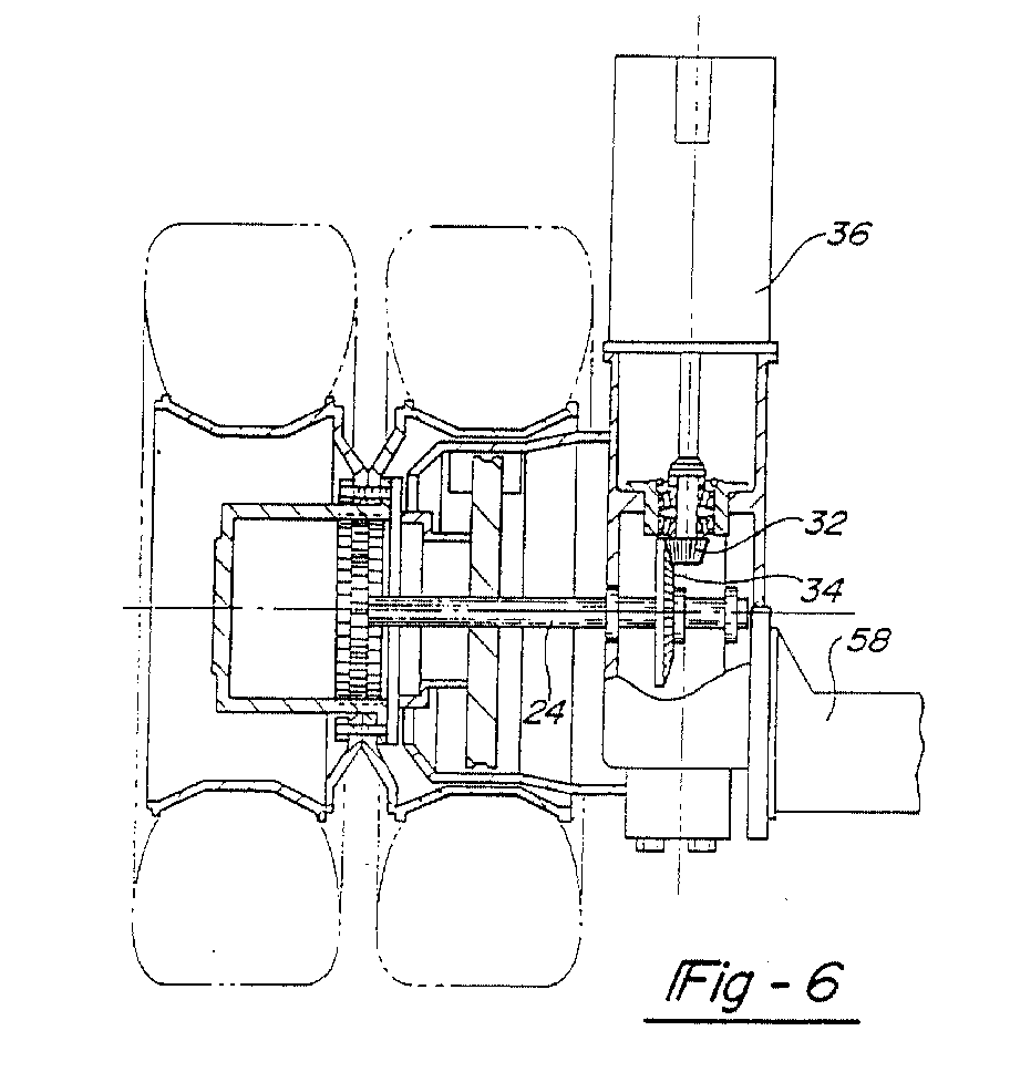
- Figure 5 and 6 show an alternate embodiment of the mounting arrangement for the first electric motor 36.
- the first electric motor 36 is shown mounted in a vertical position such that the motor axis of rotation 38 is perpendicular to the vehicle floor 18 and is perpendicular to the axis of rotation 26 of the first driving axle shaft 24.
- the first electric motor 36 is mounted either in a horizontal or vertical position.
- the electric motor 36 can be mounted at any angle with respect to the vehicle floor 18 and the axis of rotation 26 of the first driving axle shaft 24.
- Figure 7 shows an alternate embodiment of the drive unit assembly 20 in which the first unit 22 includes a third electric motor 56, in parallel driving relationship with the first electric motor 36.
- the third electric motor 56 is also used to drive the first gear set 30.
- the second unit 23 is a mirror image of the first unit 22 and includes a fourth electric motor 56, in parallel driving relationship with the second electric motor 36.
- the fourth electric motor 56 is use to drive the second gear set 30.
- the use of a third 56 and fourth electric motor 56 where packaging space is available, allows smaller gears and motors to be used, thus reducing the necessary size for the system.
- the benefits as shown in particular in Figure 1 are achieved.
- the center of the vehicle floor may be lowered significantly than compared to the prior art.
- the motors themselves are connected to drive the wheels to a non-parallel angle, they do not extend towards the center of the vehicle from the wheel for any undue amount.
- the lower floor can begin at a laterally outer position. If the motors extended on an axis parallel to the axis of the wheel, the motor would require a higher floor for more of the lateral width of the vehicle.
- FIG. 9 A preferred method of mounting the motors 36 to the vehicle is shown in Figure 9.
- the first 22 and second 23 vehicle suspension drive unit assemblies drive the wheels 19, 21 about the axis of rotation 26.
- axis 26' is parallel to driving axle shaft 24 for the wheel 19 and extends through the center of the driving axle shaft 24.
- the driving axle shaft 24 drives a first wheel hub 28 which revolves about the axis 26 of the driving axle shaft 24.
- a first suspension beam 29 extends transversely to the axis 26 of the driving axle shaft 24 and adjacent to the first wheel hub 28.
- suspension beams are utilized to interconnect a fixed wheel axle housing and brake assembly to suspension elements such as air springs.
- the first suspension beam 29 supports the electric motor 36 which generates the torque to drive the driving axle shaft 24.
- electric motor 36 defines the motor axis of rotation 38 which is transverse to the axis of rotation 26 of the driving axle shaft 24.
- a gear box or gear housing 40 interconnects the electric motor 36 and the driving axle shaft 24 and includes a pinion gear 32 and ring gear 34, shown in Figure 10A.
- the motor drive shaft 42 extends from the electric motor 36, along the axis 38 defined by the electric motor 36, and is coupled to a coaxial pinion shaft 44 which drives the pinion gear 32.
- the pinion gear 32 meshes with the ring gear 34 which revolves about the axis 26 of the driving axle shaft 24. As the ring gear 34 rotates, it drives the driving axle shaft 24 which turns the wheel hub 28.
- the motor drive shaft 42 is connected to pinion shaft 44 by a flexible coupling. As the vehicle 10 receives road load input, the suspension beam 29 will move and flex.
- the flexible coupling can include a flexible tube portion 45 made of known materials.
- the flexible coupling can also be a spherical joint 102.
- the spherical joint 102 comprises a inner portion 55 and an outer portion 57.
- the inner portion 55 has an inner flange 59 and the outer portion 57 has an outer flange 60.
- the inner flange 59 is joined to a gear box flange 62 and the outer flange 60 is joined to an electric motor flange 64.
- the inner portion 55 of the spherical joint 102 has a concave surface 66 which rotatably mates with a convex surface 68 of the outer portion 57.
- the electric motor 36 attached to the outer portion 57 of the spherical joint 102, can pivot with respect to the gear box 40 which is attached to the inner portion 55 of the spherical joint 102.
- the center of the spherical joint 102 coincides with the center of the flexible coupling.
- the inner portion 55 and outer portion 57 of the spherical joint 102 do not extend about 360 degrees about a central axis. Instead, edges such as shown at 66E and 68E are cutoff from each of the members. In this way. the members may be easily assembled.
- the inner portion 55 is moved into the outer portion 57, the outer portion 57 is moved to the position shown in phantom at 69. The outer portion is then turned to reach the assembled position such as shown in Figure 10A.
- the flexible coupling could alternatively be a universal joint or Oldham joint 104, as shown in Figure 4 as a black box to simplify the overall figure. It should be understood, that known universal joint couplings including two yokes that are driven for rotation with each other, but which may pivot relative to each other about three axes, would be preferably utilized in this embodiment.
- a moveable connection 70 interconnects the electric motor 36 and the first suspension beam 29 at a position spaced apart from the flexible coupling which interconnects the motor drive shaft 42 and the pinion shaft 44.
- Connection 70 can also be of various forms.
- a preferred connection 70 includes an electric motor mount 72 and a suspension beam mount 74 that are pivotally connected by a pivot pin 76. As the first suspension beam 29 moves up and down in response to road load input, the axis 38 of the electric motor 36 pivots relative to the first suspension beam 29.
- suspension beam 29 forms a C-shaped extension 78 which has a first end 80 and a second end 82.
- the suspension beam mount 74 that interconnects with the motor mount 72 to form the connection 70 is mounted adjacent end 80 and near the C-shaped extension 78.
- a second suspension beam 86 extending in the opposite direction from the first suspension beam 29 also forms a C-shaped extension 88 with a first end 90 and a second end 92.
- a counterweight 94 is disposed near the first end 90 of the second suspension beam 86. The counterweight 94 compensates for weight imbalance resulting from the electric motor 36 being supported by the first suspension beam 29 in a location extending to one side of the axis 26 of the driving axle shaft 24.
- the counterweight 94 can be focused or spread over the length of the second suspension beam 86, and can be cast in place, added later by attaching a weight, or by pouring molten lead into a cavity (not shown) in the second suspension beam 86.
- resilient suspension means are mounted on pads 84.
- the second suspension drive unit assembly consisting of the same or similar components as the first suspension drive unit assembly 22 is interconnected to the first suspension drive unit assembly 22 by the support beam 58.
- the second suspension drive unit assembly 23 drives a second wheel hub 100, located opposite of the first wheel hub 28 but which also revolves about the axis 26 of the driving axle shaft 24.
- Packaging advantages exist if the electric motors 36 of the first 22 and second 23 suspension drive unit assemblies extend in the same direction from the support beam 58.
- FIG. 12 Another mounting method is shown in Figure 12.
- the motor 36 for driving wheel 19 is connected to the gear box or housing 40.
- the gear housing 40 may be a portion of the axle housing for the wheel 19.
- the ring gear or bevel gear 34 is shown for driving wheel 19.
- Ring gear 34 is preferably associated with appropriate gearing to drive wheel 19.
- the gear housing 40 includes an open end 106. Open end 106 is closed by the attachment of motor 36. As shown, bolts 108 attach the gear housing flange 62 to the electric motor flange 64. Also, the drive pinion gear 32 engages and drives the ring gear 34. The pinion shaft 44 for the pinion gear 32 receives drive rotation from the motor output shaft 42. The shafts 42, 44 are interconnected by a flexible coupling 43.
- the gear housing 40 incorporates an opposed mounting portion 110 at a side of a central drive axis X of rotation opposed from the mounting of the motor 36.
- the mounting portion 110 includes a first bearing assembly 112 which mounts a shaft portion 114 for the pinion gear 32 and a second bearing assembly 116 which mounts the pinion shaft 44 for the pinion gear 32.
- the first 112 and second 116 bearing assemblies include at least one bearing, but a greater number of bearings can also be used.
- the first bearing assembly 112 includes three angular contact bearings and the second bearing assembly 116 includes a single bearing. It is necessary for pinion gear 32 to be adequately supported on bearings such that it is able to transmit sufficient torque to rotate wheel 19.
- bearings 112 are mounted in a bearing housing 118 having bearing support portions 120.
- Bearing housing 118 encloses an open end 122 of gear housing 40.
- the bearing housing 118 is inserted into the open end 122 of gear housing 40 such that the pinion gear 32 teeth and the ring gear 34 teeth do not mesh. After initial positioning of the opposed mounting portion 110, the bearing housing 118 is moved horizontally such that a flange portion 124 of the bearing housing 118 encloses the open end 122 of the gear housing 40 resulting in the meshing of pinion gear 32 teeth with ring gear 34 teeth.
- the electric motor 36 is mounted on one side of the gear housing 40, and drives the pinion gear 32, which is mounted on one side of the axis X.
- the positioning of the bearings 112 on the opposed side of the axis X from the motor 36 results in an envelope Y which does not extend far beyond the size required for wheel 19.
- the floor 18 of the vehicle 10 must rise to accommodate wheel 19, and must also extend longitudinally slightly forwardly and rearwardly from the wheel 19.
- this embodiment does not require the floor 8 to move upwardly to cover the motor 36 and gearing by any significant longitudinal amount.
Landscapes
- Engineering & Computer Science (AREA)
- Chemical & Material Sciences (AREA)
- Combustion & Propulsion (AREA)
- Transportation (AREA)
- Mechanical Engineering (AREA)
- Arrangement Or Mounting Of Propulsion Units For Vehicles (AREA)
- Gear Transmission (AREA)
Abstract
Description
Claims (18)
- An automotive vehicle drive unit assembly comprising:a first driving axle shaft (24);a second driving axle shaft (24), said first and second driving axle shafts (24) being co-linear and defining and axis of rotation (26);a first wheel hub (28) driven by said first driving axle shaft (24);a second wheel hub (28) driven by said second driving axle shaft (24), said first and second wheel hubs (28) driven about said axis of rotation (26);a first gear set (30) for driving said first wheel hub (28);a second gear set (30) for driving said second wheel hub (28);a first electric motor (36) mounted at a non-parallel angle relative to said axis of rotation of said first driving axle shaft (24)for driving said first gear set (30);a second electric motor (36) mounted at a non-parallel angle relative to said axis of rotation (26) of said second driving axle shaft (24) for driving said second gear set (30); andfirst and second planetary gear sets (46) driven by said first and second gear sets (30) resulting in gear reduction.
- An assembly as set forth in Claim 1, wherein said planetary gear sets (46) are incorporated into said wheel hubs (28).
- An assembly as set forth in Claim 1, including a first gearbox (40) for housing said first gear set (30) and a second gearbox (40) for housing said second gear set (30), said first and second gearboxes (40) being mounted to said first and second electric motors (36) respectively and wherein said first and second planetary gear sets (46) are incorporated into first and second gearboxes (40).
- An assembly as set forth in Claim 1, wherein said first gear set (30) includes a first pinion gear (32) in driving engagement with a first ring gear (34) mounted for rotation with said first wheel hub (28) and said second gear (30) set includes a second pinion gear (32) in driving engagement with a second ring gear (34) mounted for rotation with said second wheel hub (28).
- An assembly as set forth in Claim 4, wherein said first planetary gear set (46) includes a first sun gear (48) mounted for rotation with said first ring gear (34) and a first plurality of planet gears (50) in meshing engagement with a first planetary ring gear hub (52) and said second planetary gear set (46) includes a second sun gear (48) mounted for rotation with said second ring gear (34) and a second plurality of planet gears (50) in meshing engagement with a second planetary ring gear hub (52)
- An assembly as set forth in Claim 5, wherein said first planetary ring gear hub (52) drives said first wheel hub (28) and said second planetary ring gear hub (52) drives said second wheel hub(28).
- An assembly as set forth in Claim 5, wherein said first planetary ring gear hub (52) drives said first driving axle shaft (24) and said second planetary ring gear hub (52) drives said second driving axle shaft (24).
- An assembly as set forth in Claim 7 wherein said first planetary ring gear hub (52) is integrally formed with said first driving axle shaft (24) as one piece and said second planetary ring gear hub (52) is integrally formed with said second driving axle shaft (24) as one piece.
- An assembly as set forth in Claim 8, wherein said first gear set (30) and said first planetary gear set (46) are housed within a first common gearbox (40) mounted to said first electric motor (36) and said second gear set (30) and said second planetary gear set (46) are housed within a second common gearbox (40) mounted to said second electric motor (36).
- An assembly as set forth in Claim 1, including a third electric motor (56) in parallel driving relationship with said first electric motor (36) to drive said first gear set (30) and a fourth electric motor (56) in parallel driving relationship with said second electric motor (36) to drive said second gear set (30) wherein said first (36) and third (56) electric motors drive said first gear set (30) and said second (36) and fourth (56) electric motors drive said second gear set (30) independently from each other.
- An assembly as set forth in Claim 10, wherein said first (36) and said third (56) electric motors extend radially from said first gear set (30), and said second (36) and said fourth (56) electric motors extend radially from said second gear set (30).
- An assembly as set forth in Claim 11, wherein said first gear set (30) includes a first pinion gear (32) driven by said first electric motor (36) and a second pinion gear (32) driven by said third electric motor (56), said first and second pinion gears (32) for simultaneously driving a first ring gear (34) and wherein said second gear set (30) includes a third pinion gear (32) driven by said second electric motor (36) and a fourth pinion gear (32) driven by said fourth electric motor (56), said third and fourth pinion gears (32) for simultaneously driving a second ring gear (34).
- An assembly as set forth in Claim 12 wherein said first gear set (30) is housed within a first gearbox mounted to said first (36) and third (56) electric motors and said second gear set (30) is housed within a second gearbox (40) mounted to said second (36) and fourth (56) electric motors.
- An assembly as set forth in Claim 1, wherein said non-parallel angle is a perpendicular angle.
- An assembly as set forth in Claim 1, wherein one of said electric motors (36) is mounted at a 90 degree angle extending generally horizontally and forwardly relative to said axis of rotation (26) and the other of said electric motors (36) is mounted at a 90 degree angle extending generally horizontally and rearwardly relative to said axis of rotation (26).
- An assembly as set forth in Claim 1 wherein said first and second electric motors (36) are supported by a common axle housing (58) extending along said axis of rotation (26).
- An assembly as set forth in Claim 1, wherein said first and second motors (36) are mounted at a 90 degree angle extending generally vertically and upwardly from said axis of rotation (26).
- An assembly as set forth in Claim 1, wherein said first and second motors (36) are mounted at an angle extending generally horizontally and rearwardly from said axis of rotation (26).
Applications Claiming Priority (7)
| Application Number | Priority Date | Filing Date | Title |
|---|---|---|---|
| US08/801,531 US6276474B1 (en) | 1997-02-18 | 1997-02-18 | Low floor drive unit assembly for an electrically driven vehicle |
| US801532 | 1997-02-18 | ||
| US801536 | 1997-02-18 | ||
| US08/801,532 US5924504A (en) | 1997-02-18 | 1997-02-18 | Suspension drive unit assembly for an electrically driven vehicle |
| US801531 | 1997-02-18 | ||
| US08/801,536 US5878830A (en) | 1997-02-18 | 1997-02-18 | Space saving mounting for electrically driven vehicle wheels |
| EP98902488A EP0961705B1 (en) | 1997-02-18 | 1998-01-13 | Low floor drive unit assembly for an electrically driven vehicle |
Related Parent Applications (1)
| Application Number | Title | Priority Date | Filing Date |
|---|---|---|---|
| EP98902488.0 Division | 1998-08-20 |
Publications (3)
| Publication Number | Publication Date |
|---|---|
| EP1101644A2 true EP1101644A2 (en) | 2001-05-23 |
| EP1101644A3 EP1101644A3 (en) | 2002-01-02 |
| EP1101644B1 EP1101644B1 (en) | 2003-08-20 |
Family
ID=27419976
Family Applications (4)
| Application Number | Title | Priority Date | Filing Date |
|---|---|---|---|
| EP01102768A Expired - Lifetime EP1101644B1 (en) | 1997-02-18 | 1998-01-13 | Low floor drive unit assembly for an electrically driven vehicle |
| EP01102767A Expired - Lifetime EP1101643B1 (en) | 1997-02-18 | 1998-01-13 | Low floor drive unit assembly for an electrically driven vehicle |
| EP01102769A Expired - Lifetime EP1101645B1 (en) | 1997-02-18 | 1998-01-13 | Low floor drive unit assembly for an electrically driven vehicle |
| EP98902488A Expired - Lifetime EP0961705B1 (en) | 1997-02-18 | 1998-01-13 | Low floor drive unit assembly for an electrically driven vehicle |
Family Applications After (3)
| Application Number | Title | Priority Date | Filing Date |
|---|---|---|---|
| EP01102767A Expired - Lifetime EP1101643B1 (en) | 1997-02-18 | 1998-01-13 | Low floor drive unit assembly for an electrically driven vehicle |
| EP01102769A Expired - Lifetime EP1101645B1 (en) | 1997-02-18 | 1998-01-13 | Low floor drive unit assembly for an electrically driven vehicle |
| EP98902488A Expired - Lifetime EP0961705B1 (en) | 1997-02-18 | 1998-01-13 | Low floor drive unit assembly for an electrically driven vehicle |
Country Status (5)
| Country | Link |
|---|---|
| EP (4) | EP1101644B1 (en) |
| CN (2) | CN1131152C (en) |
| BR (1) | BR9807251A (en) |
| DE (4) | DE69825917T2 (en) |
| WO (1) | WO1998035848A2 (en) |
Cited By (6)
| Publication number | Priority date | Publication date | Assignee | Title |
|---|---|---|---|---|
| DE102005042098B4 (en) * | 2004-09-16 | 2012-06-06 | Arvinmeritor Technology, Llc | Electric drive axle assembly with two independent motors |
| US8423214B2 (en) | 2009-09-15 | 2013-04-16 | Kpit Cummins Infosystems, Ltd. | Motor assistance for a hybrid vehicle |
| US8596391B2 (en) | 2009-09-15 | 2013-12-03 | Kpit Cummins Infosystems Ltd | Method of converting vehicle into hybrid vehicle |
| US8606443B2 (en) | 2009-09-15 | 2013-12-10 | Kpit Cummins Infosystems, Ltd. | Motor assistance for a hybrid vehicle based on user input |
| US9227626B2 (en) | 2009-09-15 | 2016-01-05 | Kpit Technologies Limited | Motor assistance for a hybrid vehicle based on predicted driving range |
| EP4059755A1 (en) * | 2021-03-15 | 2022-09-21 | Trailer Dynamics GmbH | Axle drive system |
Families Citing this family (20)
| Publication number | Priority date | Publication date | Assignee | Title |
|---|---|---|---|---|
| DE10163628A1 (en) * | 2001-12-21 | 2003-07-10 | Zahnradfabrik Friedrichshafen | Attachment of an axle bridge |
| EP1777092B1 (en) * | 2005-10-21 | 2008-04-30 | Joseph Vögele AG | Wheel drive unit |
| SE531175C2 (en) * | 2007-05-18 | 2009-01-13 | Scania Cv Abp | Device for a motor vehicle and a vehicle equipped with such a device |
| DE102007036093A1 (en) | 2007-08-01 | 2009-02-05 | Volkswagen Ag | Wheel drive for vehicle, has driving motor, which is assigned to wheel, and transmission device for transmission of moment from driving motor assigned wheel, where driving motor is connected with wheel carrier |
| DE102007055766A1 (en) | 2007-12-12 | 2009-06-18 | Zf Friedrichshafen Ag | Drive unit for electric motor driven vehicles, particularly industrial trucks, particularly counterbalance stacker, has drive axle with two impellers propelled by individual drives |
| EP2199137B1 (en) * | 2008-12-18 | 2012-06-20 | Klingelnberg AG | Lateral wheel motor assembly |
| DE102010010438A1 (en) * | 2010-02-26 | 2011-09-01 | Dr. Ing. H.C. F. Porsche Aktiengesellschaft | Suspension for a motor vehicle with an electrical axis |
| CN101830172A (en) * | 2010-05-12 | 2010-09-15 | 湖北车桥有限公司 | Wheel-rim electric axle |
| CN101973196B (en) * | 2010-10-21 | 2016-06-22 | 刘瀚颖 | The amphibious solar automobile of sled type |
| DE102011005618A1 (en) * | 2011-03-16 | 2012-09-20 | Zf Friedrichshafen Ag | Drive device for driving a wheel for an electrically driven vehicle |
| DE102011080236A1 (en) * | 2011-08-02 | 2013-02-07 | Zf Friedrichshafen Ag | Drive device for a single wheel of a motor vehicle |
| CN102582416B (en) * | 2012-02-16 | 2015-05-13 | 吉林大学 | Full line control electric vehicle with variable kinetic characteristics |
| CN102529710A (en) * | 2012-02-17 | 2012-07-04 | 苏州市莱赛电车技术有限公司 | Double-motor input wheel-side speed reducer for electric bus |
| CN102717695B (en) * | 2012-06-18 | 2015-09-16 | 上海中科深江电动车辆有限公司 | The electric drive axle of low floor vehicle |
| US20170101000A1 (en) * | 2015-10-07 | 2017-04-13 | GM Global Technology Operations LLC | Auxiliary electric drive with wheel hub disconnect |
| US11084371B2 (en) * | 2017-01-10 | 2021-08-10 | Showa Corporation | Motor drive device |
| DE102017123586A1 (en) | 2017-10-11 | 2019-04-11 | Dr. Ing. H.C. F. Porsche Aktiengesellschaft | electric vehicle |
| DE102017123620A1 (en) | 2017-10-11 | 2019-04-11 | Dr. Ing. H.C. F. Porsche Aktiengesellschaft | Method for connecting an electric motor and a transmission, in particular in an electric vehicle |
| IT202000004966A1 (en) * | 2020-03-09 | 2021-09-09 | Brist Axle Systems S R L | INDEPENDENT SUSPENSION |
| GB2636928B (en) * | 2021-03-22 | 2026-02-18 | Allison Transm Inc | Electrified axle assembly |
Family Cites Families (22)
| Publication number | Priority date | Publication date | Assignee | Title |
|---|---|---|---|---|
| US1540526A (en) * | 1922-03-16 | 1925-06-02 | Joseph A Anglada | Motor vehicle |
| US1543044A (en) * | 1922-03-16 | 1925-06-23 | Electrocar Corp | Motor mounting and power-transmission mechanism for motor vehicles |
| GB502313A (en) | 1937-06-23 | 1939-03-15 | Bleichert Transp Anlagen G M B | Improvements in electrically propelled road vehicles |
| US2462574A (en) * | 1942-09-28 | 1949-02-22 | Daisy T Wallace | Joint for shafts |
| US2589863A (en) * | 1946-12-06 | 1952-03-18 | Orpheus F Quartullo | Gasoline-electric drive for vehicles |
| US3161083A (en) * | 1960-01-14 | 1964-12-15 | Le Tourneau Westinghouse Compa | Plural motor variable speed gear drive |
| GB1303615A (en) * | 1970-06-01 | 1973-01-17 | ||
| US3812928A (en) * | 1972-05-12 | 1974-05-28 | Allis Chalmers | Electric powered wheel |
| GB1463500A (en) * | 1973-06-09 | 1977-02-02 | Cragg H | Wheelchairs |
| US4089384A (en) * | 1977-01-31 | 1978-05-16 | Gustave Ehrenberg | Self-propelled land vehicle |
| US4270622A (en) * | 1979-06-27 | 1981-06-02 | Travis James M | Drive axle for electric vehicle |
| US4330045A (en) * | 1979-09-14 | 1982-05-18 | Reliance Electric Company | Vehicle wheel mechanism |
| US4469369A (en) * | 1980-03-07 | 1984-09-04 | Vsesojuzny Konstruktorsko-Experimentalny Institut Avtobusostroenya | Module element of city bus or like vehicle and bus assembled on the basis of such module elements |
| FR2507550B1 (en) * | 1981-06-12 | 1987-02-27 | Fenwick Manutention Ste Indle | MOTOR TURRET FOR VEHICLE, PARTICULARLY FOR HANDLING TROLLEY |
| US4658189A (en) * | 1984-09-28 | 1987-04-14 | Clark Equipment Company | Series connected series motors for independent loads |
| GB2176852B (en) * | 1985-06-20 | 1989-07-26 | Westinghouse Electric Corp | Transmission with a speed reducer and gear shifter |
| WO1990011905A1 (en) * | 1989-03-31 | 1990-10-18 | Kabushiki Kaisha Shikoku Sogo Kenkyujo | Electric car |
| CH679027A5 (en) * | 1989-06-23 | 1991-12-13 | Willi Lanker | |
| DE4112624C1 (en) * | 1991-04-18 | 1992-10-01 | Man Nutzfahrzeuge Ag, 8000 Muenchen, De | |
| DE4217260A1 (en) * | 1992-05-25 | 1993-12-02 | Zahnradfabrik Friedrichshafen | Wheel drive arrangement for omnibus - has independently driven wheels to allow passenger entry point |
| BR9202976A (en) * | 1992-07-31 | 1994-02-01 | Rockwell Braseixos Sa | PLANETARY REDUCTION FOR DRIVING AXLES |
| EP0848672B1 (en) * | 1995-09-05 | 1999-12-15 | Elin EBG Traction GmbH | Drive for a single wheel |
-
1998
- 1998-01-13 WO PCT/US1998/000514 patent/WO1998035848A2/en not_active Ceased
- 1998-01-13 DE DE69825917T patent/DE69825917T2/en not_active Expired - Lifetime
- 1998-01-13 DE DE69817407T patent/DE69817407T2/en not_active Expired - Lifetime
- 1998-01-13 DE DE69820681T patent/DE69820681T2/en not_active Expired - Lifetime
- 1998-01-13 EP EP01102768A patent/EP1101644B1/en not_active Expired - Lifetime
- 1998-01-13 EP EP01102767A patent/EP1101643B1/en not_active Expired - Lifetime
- 1998-01-13 BR BR9807251-0A patent/BR9807251A/en not_active IP Right Cessation
- 1998-01-13 DE DE69804773T patent/DE69804773T2/en not_active Expired - Fee Related
- 1998-01-13 EP EP01102769A patent/EP1101645B1/en not_active Expired - Lifetime
- 1998-01-13 CN CN98802660A patent/CN1131152C/en not_active Expired - Fee Related
- 1998-01-13 EP EP98902488A patent/EP0961705B1/en not_active Expired - Lifetime
-
2002
- 2002-04-15 CN CNB021057206A patent/CN1261317C/en not_active Expired - Fee Related
Non-Patent Citations (1)
| Title |
|---|
| None |
Cited By (7)
| Publication number | Priority date | Publication date | Assignee | Title |
|---|---|---|---|---|
| DE102005042098B4 (en) * | 2004-09-16 | 2012-06-06 | Arvinmeritor Technology, Llc | Electric drive axle assembly with two independent motors |
| US8423214B2 (en) | 2009-09-15 | 2013-04-16 | Kpit Cummins Infosystems, Ltd. | Motor assistance for a hybrid vehicle |
| US8596391B2 (en) | 2009-09-15 | 2013-12-03 | Kpit Cummins Infosystems Ltd | Method of converting vehicle into hybrid vehicle |
| US8606443B2 (en) | 2009-09-15 | 2013-12-10 | Kpit Cummins Infosystems, Ltd. | Motor assistance for a hybrid vehicle based on user input |
| US9227626B2 (en) | 2009-09-15 | 2016-01-05 | Kpit Technologies Limited | Motor assistance for a hybrid vehicle based on predicted driving range |
| US9884615B2 (en) | 2009-09-15 | 2018-02-06 | Kpit Technologies Limited | Motor assistance for a hybrid vehicle based on predicted driving range |
| EP4059755A1 (en) * | 2021-03-15 | 2022-09-21 | Trailer Dynamics GmbH | Axle drive system |
Also Published As
| Publication number | Publication date |
|---|---|
| EP1101643B1 (en) | 2004-08-25 |
| CN1131152C (en) | 2003-12-17 |
| DE69825917D1 (en) | 2004-09-30 |
| EP1101644A3 (en) | 2002-01-02 |
| DE69804773T2 (en) | 2002-11-21 |
| WO1998035848A2 (en) | 1998-08-20 |
| WO1998035848A3 (en) | 1998-12-17 |
| CN1248206A (en) | 2000-03-22 |
| EP1101645A3 (en) | 2002-01-02 |
| CN1388022A (en) | 2003-01-01 |
| EP1101643A2 (en) | 2001-05-23 |
| EP0961705B1 (en) | 2002-04-10 |
| EP1101644B1 (en) | 2003-08-20 |
| DE69817407T2 (en) | 2004-07-01 |
| DE69820681T2 (en) | 2004-12-09 |
| DE69804773D1 (en) | 2002-05-16 |
| DE69820681D1 (en) | 2004-01-29 |
| EP1101643A3 (en) | 2002-01-09 |
| EP1101645B1 (en) | 2003-12-17 |
| DE69825917T2 (en) | 2005-09-01 |
| EP1101645A2 (en) | 2001-05-23 |
| CN1261317C (en) | 2006-06-28 |
| EP0961705A2 (en) | 1999-12-08 |
| DE69817407D1 (en) | 2003-09-25 |
| BR9807251A (en) | 2000-05-02 |
Similar Documents
| Publication | Publication Date | Title |
|---|---|---|
| EP1101644B1 (en) | Low floor drive unit assembly for an electrically driven vehicle | |
| US5924504A (en) | Suspension drive unit assembly for an electrically driven vehicle | |
| US7866423B2 (en) | Low floor drive unit assembly for an electrically driven vehicle | |
| US3420327A (en) | Rigid drive axle for motor vehicles | |
| CN102361773B (en) | Transmission unit having a transversal degree of freedom | |
| CA2873705C (en) | System for driving the drive wheels of an electric or hybrid vehicle | |
| US20030111280A1 (en) | Drive system for an electric vehicle | |
| US7568546B2 (en) | Low load floor motor vehicle | |
| US6431298B1 (en) | Drive unit assembly for an electrically driven vehicle | |
| US5878830A (en) | Space saving mounting for electrically driven vehicle wheels | |
| US11084371B2 (en) | Motor drive device | |
| EP0931684A1 (en) | Vehicle, particularly electrically driven vehicle | |
| US6193007B1 (en) | Rear suspension and drive axle assembly | |
| EP1344661B1 (en) | A suspension system for a low floor vehicle | |
| US20010025737A1 (en) | Vehicle suspension system | |
| CN114701318B (en) | A torsion beam type semi-independent suspension electric drive rear axle assembly | |
| EP1348587A2 (en) | A suspension system for a low floor vehicle | |
| EP4446210A1 (en) | Multi-stage chain transmission structure for all-terrain kart | |
| US20240116355A1 (en) | Vehicle and Suspension Arm Assembly | |
| JPH1044795A (en) | Automobile, driving wheel and axle assembly | |
| US6659217B2 (en) | Drive assembly for low floor vehicle | |
| WO2001010663A1 (en) | Rear suspension and drive axle assembly for a low floor vehicle |
Legal Events
| Date | Code | Title | Description |
|---|---|---|---|
| PUAI | Public reference made under article 153(3) epc to a published international application that has entered the european phase |
Free format text: ORIGINAL CODE: 0009012 |
|
| AC | Divisional application: reference to earlier application |
Ref document number: 961705 Country of ref document: EP |
|
| AK | Designated contracting states |
Kind code of ref document: A2 Designated state(s): DE FR GB IT SE |
|
| RIN1 | Information on inventor provided before grant (corrected) |
Inventor name: RUPPERT, MALCOLM F. JR. Inventor name: SULLIVAN, WILLIAM CARL Inventor name: SWANSON, GLEN E. Inventor name: BRILL, LAWRENCE DOYLE |
|
| PUAL | Search report despatched |
Free format text: ORIGINAL CODE: 0009013 |
|
| AK | Designated contracting states |
Kind code of ref document: A3 Designated state(s): DE FR GB IT SE |
|
| 17P | Request for examination filed |
Effective date: 20020620 |
|
| AKX | Designation fees paid |
Free format text: DE FR GB IT SE |
|
| GRAH | Despatch of communication of intention to grant a patent |
Free format text: ORIGINAL CODE: EPIDOS IGRA |
|
| GRAS | Grant fee paid |
Free format text: ORIGINAL CODE: EPIDOSNIGR3 |
|
| GRAA | (expected) grant |
Free format text: ORIGINAL CODE: 0009210 |
|
| AC | Divisional application: reference to earlier application |
Ref document number: 0961705 Country of ref document: EP Kind code of ref document: P |
|
| AK | Designated contracting states |
Designated state(s): DE FR GB IT SE |
|
| REG | Reference to a national code |
Ref country code: GB Ref legal event code: FG4D |
|
| REF | Corresponds to: |
Ref document number: 69817407 Country of ref document: DE Date of ref document: 20030925 Kind code of ref document: P |
|
| REG | Reference to a national code |
Ref country code: SE Ref legal event code: TRGR |
|
| ET | Fr: translation filed | ||
| PLBE | No opposition filed within time limit |
Free format text: ORIGINAL CODE: 0009261 |
|
| STAA | Information on the status of an ep patent application or granted ep patent |
Free format text: STATUS: NO OPPOSITION FILED WITHIN TIME LIMIT |
|
| 26N | No opposition filed |
Effective date: 20040524 |
|
| PGFP | Annual fee paid to national office [announced via postgrant information from national office to epo] |
Ref country code: SE Payment date: 20060127 Year of fee payment: 9 |
|
| PG25 | Lapsed in a contracting state [announced via postgrant information from national office to epo] |
Ref country code: SE Free format text: LAPSE BECAUSE OF NON-PAYMENT OF DUE FEES Effective date: 20070114 |
|
| EUG | Se: european patent has lapsed | ||
| GBPC | Gb: european patent ceased through non-payment of renewal fee |
Effective date: 20070113 |
|
| PG25 | Lapsed in a contracting state [announced via postgrant information from national office to epo] |
Ref country code: GB Free format text: LAPSE BECAUSE OF NON-PAYMENT OF DUE FEES Effective date: 20070113 |
|
| PGFP | Annual fee paid to national office [announced via postgrant information from national office to epo] |
Ref country code: GB Payment date: 20060104 Year of fee payment: 9 |
|
| PGFP | Annual fee paid to national office [announced via postgrant information from national office to epo] |
Ref country code: FR Payment date: 20120202 Year of fee payment: 15 |
|
| PGFP | Annual fee paid to national office [announced via postgrant information from national office to epo] |
Ref country code: DE Payment date: 20120111 Year of fee payment: 15 |
|
| PGFP | Annual fee paid to national office [announced via postgrant information from national office to epo] |
Ref country code: IT Payment date: 20120118 Year of fee payment: 15 |
|
| REG | Reference to a national code |
Ref country code: FR Ref legal event code: ST Effective date: 20130930 |
|
| PG25 | Lapsed in a contracting state [announced via postgrant information from national office to epo] |
Ref country code: DE Free format text: LAPSE BECAUSE OF NON-PAYMENT OF DUE FEES Effective date: 20130801 |
|
| REG | Reference to a national code |
Ref country code: DE Ref legal event code: R119 Ref document number: 69817407 Country of ref document: DE Effective date: 20130801 |
|
| PG25 | Lapsed in a contracting state [announced via postgrant information from national office to epo] |
Ref country code: FR Free format text: LAPSE BECAUSE OF NON-PAYMENT OF DUE FEES Effective date: 20130131 |
|
| PG25 | Lapsed in a contracting state [announced via postgrant information from national office to epo] |
Ref country code: IT Free format text: LAPSE BECAUSE OF NON-PAYMENT OF DUE FEES Effective date: 20130113 |