EP1101587A2 - Multi-path compression moding apparatus - Google Patents
Multi-path compression moding apparatus Download PDFInfo
- Publication number
- EP1101587A2 EP1101587A2 EP00125131A EP00125131A EP1101587A2 EP 1101587 A2 EP1101587 A2 EP 1101587A2 EP 00125131 A EP00125131 A EP 00125131A EP 00125131 A EP00125131 A EP 00125131A EP 1101587 A2 EP1101587 A2 EP 1101587A2
- Authority
- EP
- European Patent Office
- Prior art keywords
- molten plastic
- manifold
- plastic
- cutting blades
- pellets
- Prior art date
- Legal status (The legal status is an assumption and is not a legal conclusion. Google has not performed a legal analysis and makes no representation as to the accuracy of the status listed.)
- Withdrawn
Links
Images


Classifications
-
- B—PERFORMING OPERATIONS; TRANSPORTING
- B29—WORKING OF PLASTICS; WORKING OF SUBSTANCES IN A PLASTIC STATE IN GENERAL
- B29C—SHAPING OR JOINING OF PLASTICS; SHAPING OF MATERIAL IN A PLASTIC STATE, NOT OTHERWISE PROVIDED FOR; AFTER-TREATMENT OF THE SHAPED PRODUCTS, e.g. REPAIRING
- B29C43/00—Compression moulding, i.e. applying external pressure to flow the moulding material; Apparatus therefor
- B29C43/02—Compression moulding, i.e. applying external pressure to flow the moulding material; Apparatus therefor of articles of definite length, i.e. discrete articles
- B29C43/04—Compression moulding, i.e. applying external pressure to flow the moulding material; Apparatus therefor of articles of definite length, i.e. discrete articles using movable moulds
- B29C43/06—Compression moulding, i.e. applying external pressure to flow the moulding material; Apparatus therefor of articles of definite length, i.e. discrete articles using movable moulds continuously movable in one direction, e.g. mounted on chains, belts
- B29C43/08—Compression moulding, i.e. applying external pressure to flow the moulding material; Apparatus therefor of articles of definite length, i.e. discrete articles using movable moulds continuously movable in one direction, e.g. mounted on chains, belts with circular movement, e.g. mounted on rolls, turntables
-
- B—PERFORMING OPERATIONS; TRANSPORTING
- B29—WORKING OF PLASTICS; WORKING OF SUBSTANCES IN A PLASTIC STATE IN GENERAL
- B29C—SHAPING OR JOINING OF PLASTICS; SHAPING OF MATERIAL IN A PLASTIC STATE, NOT OTHERWISE PROVIDED FOR; AFTER-TREATMENT OF THE SHAPED PRODUCTS, e.g. REPAIRING
- B29C31/00—Handling, e.g. feeding of the material to be shaped, storage of plastics material before moulding; Automation, i.e. automated handling lines in plastics processing plants, e.g. using manipulators or robots
- B29C31/04—Feeding of the material to be moulded, e.g. into a mould cavity
- B29C31/042—Feeding of the material to be moulded, e.g. into a mould cavity using dispensing heads, e.g. extruders, placed over or apart from the moulds
- B29C31/048—Feeding of the material to be moulded, e.g. into a mould cavity using dispensing heads, e.g. extruders, placed over or apart from the moulds the material being severed at the dispensing head exit, e.g. as ring, drop or gob, and transported immediately into the mould, e.g. by gravity
-
- B—PERFORMING OPERATIONS; TRANSPORTING
- B29—WORKING OF PLASTICS; WORKING OF SUBSTANCES IN A PLASTIC STATE IN GENERAL
- B29C—SHAPING OR JOINING OF PLASTICS; SHAPING OF MATERIAL IN A PLASTIC STATE, NOT OTHERWISE PROVIDED FOR; AFTER-TREATMENT OF THE SHAPED PRODUCTS, e.g. REPAIRING
- B29C43/00—Compression moulding, i.e. applying external pressure to flow the moulding material; Apparatus therefor
- B29C43/32—Component parts, details or accessories; Auxiliary operations
- B29C43/34—Feeding the material to the mould or the compression means
-
- B—PERFORMING OPERATIONS; TRANSPORTING
- B29—WORKING OF PLASTICS; WORKING OF SUBSTANCES IN A PLASTIC STATE IN GENERAL
- B29C—SHAPING OR JOINING OF PLASTICS; SHAPING OF MATERIAL IN A PLASTIC STATE, NOT OTHERWISE PROVIDED FOR; AFTER-TREATMENT OF THE SHAPED PRODUCTS, e.g. REPAIRING
- B29C43/00—Compression moulding, i.e. applying external pressure to flow the moulding material; Apparatus therefor
- B29C43/32—Component parts, details or accessories; Auxiliary operations
- B29C2043/3272—Component parts, details or accessories; Auxiliary operations driving means
-
- B—PERFORMING OPERATIONS; TRANSPORTING
- B29—WORKING OF PLASTICS; WORKING OF SUBSTANCES IN A PLASTIC STATE IN GENERAL
- B29C—SHAPING OR JOINING OF PLASTICS; SHAPING OF MATERIAL IN A PLASTIC STATE, NOT OTHERWISE PROVIDED FOR; AFTER-TREATMENT OF THE SHAPED PRODUCTS, e.g. REPAIRING
- B29C33/00—Moulds or cores; Details thereof or accessories therefor
- B29C33/34—Moulds or cores; Details thereof or accessories therefor movable, e.g. to or from the moulding station
- B29C33/36—Moulds or cores; Details thereof or accessories therefor movable, e.g. to or from the moulding station continuously movable in one direction, e.g. in a closed circuit
-
- B—PERFORMING OPERATIONS; TRANSPORTING
- B29—WORKING OF PLASTICS; WORKING OF SUBSTANCES IN A PLASTIC STATE IN GENERAL
- B29L—INDEXING SCHEME ASSOCIATED WITH SUBCLASS B29C, RELATING TO PARTICULAR ARTICLES
- B29L2031/00—Other particular articles
- B29L2031/56—Stoppers or lids for bottles, jars, or the like, e.g. closures
- B29L2031/565—Stoppers or lids for bottles, jars, or the like, e.g. closures for containers
-
- Y—GENERAL TAGGING OF NEW TECHNOLOGICAL DEVELOPMENTS; GENERAL TAGGING OF CROSS-SECTIONAL TECHNOLOGIES SPANNING OVER SEVERAL SECTIONS OF THE IPC; TECHNICAL SUBJECTS COVERED BY FORMER USPC CROSS-REFERENCE ART COLLECTIONS [XRACs] AND DIGESTS
- Y10—TECHNICAL SUBJECTS COVERED BY FORMER USPC
- Y10S—TECHNICAL SUBJECTS COVERED BY FORMER USPC CROSS-REFERENCE ART COLLECTIONS [XRACs] AND DIGESTS
- Y10S425/00—Plastic article or earthenware shaping or treating: apparatus
- Y10S425/809—Seal, bottle caps only
Definitions
- the present invention relates to a method and apparatus for cutting discrete quantities of molten plastic material from a supply of molten plastic material for subsequent compression molding of the plastic material into plastic articles. More particularly, the invention relates to a plurality of cutters which rotate relative to a plurality of molten plastic delivery nozzles to cut pellets of molten plastic from the nozzles and to carry the thus cut pellets of molten plastic into cavities for compression molding articles.
- U.S. Patent No. 4,277,431 to Peller, hereby incorporated by reference, discloses an apparatus for cutting discrete quantities or pellets of molten plastic material for subsequent placement in respective mold cavities. This apparatus is particularly suited for use in the manufacture of closures by compression molding, including the formation of compression molded closure shells, and the formation of compression molded liners within associated closure shells.
- the apparatus of U.S. Pat. No. 4,277,431 includes a nozzle through which molten plastic material is delivered from an associated extruder or the like, and a rotatably driven cutting blade which is rotated with respect to the nozzle. As plastic is extruded from the nozzle, a discrete quantity or pellet of plastic material is cut during each rotation of the associated cutting blade. Immediately thereafter, the severed plastic pellet is moved from the face of the nozzle by the cutting blade for delivery to a respective mold cavity.
- the mold cavity may comprise either a female mold die for formation of a closure shell by compression molding, or a closure shell within which the molten plastic is compression molded for formation of a sealing liner.
- the cutter apparatus of U.S. Patent 4,227,431 is configured to facilitate separation of each plastic pellet from the cutting blade by creating a slight mechanical interference between the cutting blade and the face of the associated nozzle.
- the blade As the cutting blade rotates with respect to the nozzle, the blade is flexed or deflected as it engages the nozzle face and severs the extruded plastic material.
- the cutting blade disengages the face of the nozzle, thereby rapidly accelerating the pellet to facilitate its separation from the blade and delivery of the pellet to one of the associated cavities.
- This cutting and subsequent "flicking" like action of the cutting blade is sometimes referred to as the "cut-and-flip" portion of each cutting cycle.
- U.S. Patent No. 5,596,251 describes a cutter apparatus driven by a servo motor, the operation of which is coordinated with an associated rotary carousel on which cavities are successively presented to the cutter apparatus.
- the servo motor is operated to create a period of distinct deceleration during each rotary cutting cycle, thereby separating the molten plastic from the surface of the cutting blade.
- the cutter apparatus disclosed in each of the aforementioned patents includes a single rotating cutter which cuts and disperses a single pellet during each rotation.
- the throughput of such apparatus is thus limited by the rotational speed of the single cutter.
- To increase the overall throughput of the compression molding apparatus requires additional cutter apparatuses and associated carousels which requires costly additional factory floor space.
- the present inventors have recognized that it would be desirable to provide a cutter apparatus for cutting molten plastic pellets from a source of molten plastic material and delivering the pellets into successive cavities for subsequent compression molding which could be effectively operated at a high rate of speed to produce a high rate of molded articles.
- the apparatus desirably would reliably operate to produce a high percentage of flawlessly molded articles.
- the apparatus desirably would require a minimum of factory floor space.
- the present invention is directed to a plastic pellet cutting and delivery system particularly suited for use in compression molding of plastic closure shells, and plastic liners in closure shells.
- the present invention includes a high throughput compression molding apparatus having a rotatable bank of cutters operatively associated with a bank of molten plastic delivery nozzles.
- the invention includes a plurality of molding blocks, each block having a row of molding cavities for successively receiving a row of plastic pellets cut by the bank of cutters from the bank of molten plastic delivery nozzles.
- the molding blocks are advantageously carried on a revolving carousel.
- a compression molding device such as disclosed in U.S. Patents 4,343,754 or 4,497,765 can be used to mold the plastic pellets carried by the blocks into articles, such as threaded, tamper-indicating plastic closures or liners for closures.
- the present system is used in conjunction with a rotary compression molding apparatus, which typically includes a rotating carousel or turret which carries cavities in the form of mold dies or closure shells.
- the carousel circulates molding blocks having radially arranged rows of cavities.
- the present system effects delivery of plural discrete quantities of molten plastic material (i.e., plastic pellets) to the rows of circulating cavities by the provision of an extruder or like apparatus which provides a source of molten plastic material, and a plurality of the cutting blades driven with respect to nozzles flow connected to the extruder.
- a precision servo motor drives the cutter shaft via a toothed timing belt and pulley arrangement.
- the present invention incorporates a multi-cutter comprising a plurality of cutter assemblies mounted on a cutter shaft, the cutter shaft being rotated about its axis by a servo motor.
- the cutter assembly can be as described in U.S. Serial No. 09/444,936, filed on November 22, 1999, and identified by attorney docket number HCI0467P00480US, and entitled: "Rotary Cutter For Cutting, Measuring, and Dispensing Molten Plastic," herein incorporated by reference.
- Each such cutter assembly comprises a cutter body which is held substantially within a radial bore formed in an end portion of a cutter shaft, and a protruding cutter head extending from the cutter body.
- the cutter shaft includes one or more internal air passages for pressurized air delivery to each of the cutter bodies.
- Each cutter assembly can include a plunger which reciprocates adjacent to the cutter head to displace a plastic pellet held by the cutter head.
- Each cutter body can include a series of air apertures directed toward an internal region of the respective cutter head for passing pressurized air into the cutter head to dislodge a plastic pellet held thereby.
- the air apertures are in flow communication with one of the internal air passages within the cutter shaft.
- Internal cooling fluid channels through the cutter shaft are in flow communication with an annular area between each cutter body and an inside wall of the respective radial bore of the cutter shaft for maintaining the cutter bodies at a desired temperature during operation.
- the cutter shaft is rotated within a rotary union block.
- the cutter shaft includes one or more first annular channels around its circumference in flow communication with the internal air passages.
- the cutter shaft also includes second and third annular channels around its circumference and in flow communication with the two internal cooling channels respectively.
- the rotary union block includes corresponding channels or passages in flow communication with the first, second and third annular channels of the cutter shaft, such that pressurized air and cooling water can be sealingly transferred between the rotary union block and the cutter shaft given that the cutter shaft is rotating and the union block is stationary.
- the bank of extrusion nozzles receive flow of molten plastic from a manifold assembly.
- the manifold assembly includes an inlet adapter, open into a first cross shaped or "clover leaf” shaped block manifold which separates the flow into four divergent flow paths.
- the four flow paths each connect to one of four volumetric metering or proportioning pumps.
- the volumetric metering pumps are used to provide consistent volume flow and pressure of the molten plastic.
- the pumps are each connected at outlets thereof to a second cross shaped or "clover leaf” shaped block manifold.
- the second manifold includes channels that direct the four flow paths into four adjacent outlets.
- the four outlets are connected by tubes, such as hot runners, to a right angle or L-shaped manifold block.
- the right angle manifold block is connected to a bank of nozzles.
- the first and second manifolds, the tubes, and the right angle manifold block are all heated and insulated to maintain the molten plastic at a
- the manifold assembly thus cooperates with the bank of delivery nozzles to deliver a controlled flow of molten plastic to the nozzles.
- the bank of rotary cutters are arranged to cooperate with the bank of delivery nozzles to separate rows of pellets of molten plastic extruded from the nozzles and to dispense the rows of pellets into successively presented molding blocks each having a row of cavities, for subsequent compression molding into articles.
- a greatly increased throughput of plastic pellets deposited into molding cavities for compression molding is achieved without substantially increasing a floor space requirement for the compression molding apparatus.
- FIGURE 1 illustrates a compression molding apparatus 20 for formation of closure shells, liners, or other articles by compression molding.
- the apparatus 20 includes an annular carousel 26 (shown in fragmentary fashion) which supports a plurality of molding blocks 32 arranged in a circle,.
- the carousel 26 rotates in the direction R about a vertical centerline 26a of the carousel.
- Each block 32 includes a plurality of cavities 30 arranged in a row and aligned radially of the centerline 26a of the carousel 26. In the illustrated embodiment each block 32 includes four cavities 30.
- the apparatus 20 also includes a molten plastic delivery assembly 34.
- the delivery assembly 34 includes a manifold assembly 35 (shown schematically as a box in FIGURE 1) that is shown and described in detail below with respect to FIGURES 7 through 9.
- the assembly 34 includes an L-shaped manifold block 46 and a plurality of nozzles 38a-38d for dispensing molten plastic material.
- the manifold block 46 is heated to retain the molten plastic in its molten state.
- the apparatus 20 includes a multi-cutter 40 that has a plurality of cutter assemblies 40a-40d (shown in FIGURE 3) that remove plastic material from the nozzles 38a-38d to be deposited into the cavities 30 of each successively presented block 32.
- the cutter assemblies 40a-40d are mounted on a shaft 41 which is conjointly rotated via a driven pulley 63 connected thereto, which is driven by a belt 62.
- the belt is also wrapped around a drive pulley 61 which is driven by a stepper motor or a precision servo motor 60.
- the belt 62 is shown as a line but in practice would preferably be a flat, elastomeric fan belt or a timing chain.
- the shaft 41 is journaled in a rotary union 50 that supplies air 51 and cooling fluid 52 to the cutters 40 as described below.
- the carousel is driven in a synchronized step fashion such that the rotating multi-cutter 40 separates pellets of molten plastic from the nozzles 38a-38d and deposit the pellets into the four cavities 30 of each successive block 32.
- the pellets are compression molded at a molding station 53.
- the method and apparatus for compression molding can be as described in U.S. Patents 4,343,754 or 4,497,765, herein incorporated by reference.
- a removal station 54 the molded and cooled articles can be removed from each block 32, successively.
- the molten plastic delivery system 34 can advantageously be controllable to maintain a steady and precise, selected temperature using heating elements associated with the manifold block 46 and the manifold assembly 35.
- the system can be insulated to assist in controlling the temperature of the molten plastic.
- FIGURE 2 shows the rotary union block 50 arranged on an opposite side of the driven pulley 63 as the multi-cutter 40.
- the shaft extends into the rotary union block 50.
- the rotary union block 50 includes tube connections 64 for flow-connecting the union block 50 to a cooling fluid source conduit and cooling fluid return conduit, and to a source of pressurized air and a vent as needed.
- the multi-cutter 40 includes the four cutter assemblies 40a, 40b, 40c, 40d which respectively align with the four nozzles 38a, 38b, 38c, 38d as the multi-cutter 40 is rotated about its longitudinal axis by the driven pulley 63.
- FIGURE 2 illustrates that the rotating shaft 41 mounts the cutter assemblies 40a, 40b, 40c, 40d which extend radially therefrom.
- the shaft 41 includes axially arranged flow channels which deliver pressurized air to each cutter assembly.
- the pressurized air is used to assist in expelling the plastic pellet removed and carried away from the nozzles 38a, 38b, 38c, 38d, respectively.
- the air channels and cutters are arranged as disclosed in copending application , filed , attorney docket number HCI0467P0480US, filed on the same day as the present application and herein incorporated by reference.
- the four cutter assemblies 40a, 40b, 40c, 40d can be arranged on a common air channel to expel four plastic pellets simultaneously or can be on individual air channels such that the timing of pellet ejection of each cutter can be precisely adjusted.
- an intelligent logic controller PLC
- PLC intelligent logic controller
- a sequential ejection of the pellets from the four cutter assemblies 40a-40d (and from the additional cutters 42a-42d, described below) is contemplated due to the fact that the radially outermost cavities of the successively presented molding blocks on the revolving carousel are moving at a greater velocity than the radially innermost cavities.
- Cooling fluid channels are provided which extend along the shaft axially to cool the rotating multi-cutter 40 as described in the aforementioned copending application.
- a second set of cutter assemblies 42a, 42b, 42c, 42d can be arranged at 180° diametrically opposite the cutter assemblies 40a-40d.
- twice the throughput can be achieved.
- the apparatus 20 also includes a waste/purge removal duct 54.
- this duct provides an alternate location for dispensing molded plastic pellets rather than into the cavities 30. This is particularly useful during start up operations.
- the plastic pellets can be deposited into the waste/purge duct 54 until the quality or timing of the formed pellets is acceptable to begin depositing pellets into the cavities 30 of the blocks 32.
- the duct includes an angled facing wall 55 with spaced apart cavity-simulating apertures 56a-56d. Pellets are ejected from the cutter assemblies 40a-40d and 42a-42d and into the apertures 56a-56d during practice, start-up or testing. The pellets traveling through the duct 54 are collected into a storage container 55 for recycling or disposal.
- FIGURE 4 illustrates the manifold block having a nozzle end 147 and an inlet end 148.
- the molten plastic nozzles 38a, 38b, 38c, 38d are arranged at the nozzle end 147.
- the nozzles are progressively extended from the manifold block 46, with the outside nozzle 38a, seen in a radial direction from a center line of the carousel 26, being the most recessed.
- the inside nozzle 38d is the most extended from the manifold block 46.
- FIGURES 6A through 6C disclose the L-shaped manifold block 46 in more detail.
- the manifold block 46 includes L-shaped molten plastic channels 102a, 102b, 102c, 102d which extend from the inlet end 148 to the outlet end 147. Extending through a top wall 104 of the manifold block 46 are inlet temperature ports 104a, 104b, 104c, 104d, and outlet temperature ports 106a, 106b, 106c, 106d. Temperature probes can be inserted into the ports 104a-104d and 106a-106d.
- Two series of parallel heater bores are arranged into the manifold block 46. These heater bores receive heating elements, such as electric heating elements, which maintain the manifold block, and thus the molten plastic therein, at the desired temperature before exiting the nozzles 38a-38d.
- a first set of bores 108a, 108b, 108c, 108d extend from a lateral side 112 of the manifold block 46 toward the inlet end 148.
- a second set of bores 110a, 110b, 110c, 110d extend from an adjacent side 114 toward the outlet end 147.
- the bores 108a-108d and 110a-110d cris-cross, but occupy two different levels within the manifold block 46.
- a plurality of threaded bores 122 are formed into the inlet end 148 for receiving fasteners to connect the manifold assembly 35 as described below.
- a further plurality of threaded bores 124 are provided on the outlet end 147 to attach the nozzles 38a-38d. Two fasteners, and two threaded bores 124, are used for attachment of each nozzle to the manifold block 46.
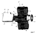
- FIGURE 7 illustrates a manifold assembly 35 connected to the inlet end 148 of the manifold block 46.
- the manifold assembly includes a first cross-shaped or "clover leaf' shaped block manifold 74 which is connected to a second cross-shaped or “clover leaf” shaped block manifold 76 via four volumetric metering pumps 82, 84, 86, 88. Each metering pump acts to pump molten plastic through the manifold assembly 35, at a constant rate through the manifold block 46 to the nozzles 38a-38d.
- the first manifold 74 is flow-connected to a manifold connector 77 which receives an input stream of molten plastic through a central aperture 78.
- the molten plastic stream is divided and directed by the manifold 74 to the inlet of each of the pumps 82, 84, 86, 88 which deliver four streams of molten plastic into the second manifold 76 wherein the molten plastic is directed radially inwardly to each of four heated pipe sections 90, 92, 94, 96 which are in turn connected to the four molten plastic channels 102a-102d of the manifold block 46.
- FIGURE 8 shows that the manifold connector 77 is sealed by an O-ring 130 to an internal channel 132 in the manifold 74 which is connected to one molten plastic delivery channel 134c of four molten plastic delivery channels 134a-134d, which is sealingly connected to the proportioning pump 82.
- An outlet of the pump 82 is connected to one radially directed channel 144c of four radially directed channels 144a-144d which is connected to one molten plastic outlet channel 146c of four molten plastic outlet channels 146a-146d which is sealingly connected by an O-ring 148 to the heated pipe section 96.
- Each of the pumps 82, 84, 86, 88 is connected similarly, forming four discrete flow paths from the inlet of the first manifold 74 to the four heated pipe sections 90, 92, 94, 96 which are connected to the L-shaped manifold block 46.
- the first manifold 74 includes four arms 74a-74d.
- Each of the arms includes heating wires arranged on opposite faces of the manifold to maintain the plastic in a preselected molten state within the manifold.
- the arm 74a includes a heating wire loop 175a on the first face 177a, and an identical wire loop 175b on the second, opposite face 177b.
- Each of the arms include thermocouple sensor.
- the arm 74a includes the thermocouple sensor 178.
- the second manifold 76 includes four arms 76a-76d.
- Each of the arms includes heating wires arranged on opposite faces of the manifold to maintain the plastic in a molten state within the manifold.
- the arm 76a includes a heating wire loop 180a on the first face 181a, and an identical wire loop 180b on the second, opposite face 181b.
- Each of the arms include thermocouple sensor.
- the arm 76a includes the thermocouple sensor 182.
- the second, outlet manifold 76 is connected to the four heated pipes 90,92,94,96. Each of the pipes is heated by a separate heating element 186.
- each heater wire and thermocouple of the manifolds 74, 76, the heater wires for the heated pipes, the heating elements in the manifold block 46, and the temperature probes in the manifold block are connected to a monitoring and control system which maintains the molten plastic flowing from the four heated pipes 90, 92, 94, 96 and the four nozzles 38a-38d with a preselected, equal temperature, pressure and flow rate.
- FIGURES 10 through 12 illustrates an improved thermocouple assembly 200 advantageously incorporated into the apparatus of the present invention.
- the assembly is illustrated as installed into a nozzle block 300.
- the assembly 200 can be installed at any position in the assembly shown in FIGURES 1 through 9 where a molten plastic temperature reading or signal is desired.
- the assembly 200 can be installed into one of the temperature ports 104a-104d and/or one of the temperature ports 106a-106d of the manifold block 46.
- the assembly includes a thermocouple element 202 which is inserted into a housing 210.
- the housing includes a tool engageable head 214 and a depending skirt 216.
- the skirt 216 holds a stack of seal elements 220 which form a packing 218.
- the skirt 216 has external threads 224 which engage internal threads 324 of a bore 326 of the nozzle block 300, or other structure from which an accurate molten plastic temperature is required.
- the element 202 can be connected to local temperature gauge or can provide a signal to a centralized control.
- the probe 202 is slid into the housing 210 to a desired depth of the probe end into a molten plastic delivery channel 330.
- the housing 210 is threadedly driven into the bore 326 of the nozzle block 300 by tool driven rotation of the head 214.
- the packing 218 is compressed against a bottom 334 of the bore 326 and a bottom 216 of the head 214. The packing is also compressed radially against the probe 202 to seal thereto.
- FIGURES 10-12 provides an easily adjustable and sealable temperature probe for use in molten plastic channels, especially in a compression molding apparatus.
Abstract
Description
- The present invention relates to a method and apparatus for cutting discrete quantities of molten plastic material from a supply of molten plastic material for subsequent compression molding of the plastic material into plastic articles. More particularly, the invention relates to a plurality of cutters which rotate relative to a plurality of molten plastic delivery nozzles to cut pellets of molten plastic from the nozzles and to carry the thus cut pellets of molten plastic into cavities for compression molding articles.
- U.S. Patent No. 4,277,431, to Peller, hereby incorporated by reference, discloses an apparatus for cutting discrete quantities or pellets of molten plastic material for subsequent placement in respective mold cavities. This apparatus is particularly suited for use in the manufacture of closures by compression molding, including the formation of compression molded closure shells, and the formation of compression molded liners within associated closure shells. U.S. Pat. Nos. 4,343,754 to Wilde et al., and 4,497,765 to Wilde et al., both hereby incorporated by reference, disclose compression molding of threaded, tamper-indicating plastic closures, and compression molding of liners in such closures, for which manufacturing processes the apparatus of the above U.S. Pat. No. 4,277,431 is suited for use.
- The apparatus of U.S. Pat. No. 4,277,431 includes a nozzle through which molten plastic material is delivered from an associated extruder or the like, and a rotatably driven cutting blade which is rotated with respect to the nozzle. As plastic is extruded from the nozzle, a discrete quantity or pellet of plastic material is cut during each rotation of the associated cutting blade. Immediately thereafter, the severed plastic pellet is moved from the face of the nozzle by the cutting blade for delivery to a respective mold cavity. The mold cavity may comprise either a female mold die for formation of a closure shell by compression molding, or a closure shell within which the molten plastic is compression molded for formation of a sealing liner.
- The cutter apparatus of U.S. Patent 4,227,431 is configured to facilitate separation of each plastic pellet from the cutting blade by creating a slight mechanical interference between the cutting blade and the face of the associated nozzle. Thus, as the cutting blade rotates with respect to the nozzle, the blade is flexed or deflected as it engages the nozzle face and severs the extruded plastic material. As the blade continues to rotate, with the severed plastic material carried on the flexed surface of the cutting blade, the cutting blade disengages the face of the nozzle, thereby rapidly accelerating the pellet to facilitate its separation from the blade and delivery of the pellet to one of the associated cavities. This cutting and subsequent "flicking" like action of the cutting blade is sometimes referred to as the "cut-and-flip" portion of each cutting cycle.
- The above patent contemplates that the disclosed cutting apparatus be mechanically-driven from the associated molding apparatus, thus effecting the desired synchronous operation of the cutter. However, it will be appreciated that increases or decreases in production speed necessarily result in corresponding variation in the "cut-and-flip" portion of the cutting cycle, which can create undesirable variability in the speed, direction, rotational velocity, and orientation of the plastic pellet as it is delivered to the associated cavity. This can, in turn, create problems regarding pellet placement, orientation, and an undesirable tendency of he pellet to bounce upon delivery into the associated cavity.
- U.S. Patent No. 5,596,251 describes a cutter apparatus driven by a servo motor, the operation of which is coordinated with an associated rotary carousel on which cavities are successively presented to the cutter apparatus. In order to effect separation of each discrete quantity of plastic material from the cutting blade of the cutter apparatus, the servo motor is operated to create a period of distinct deceleration during each rotary cutting cycle, thereby separating the molten plastic from the surface of the cutting blade.
- The cutter apparatus disclosed in each of the aforementioned patents includes a single rotating cutter which cuts and disperses a single pellet during each rotation. The throughput of such apparatus is thus limited by the rotational speed of the single cutter. To increase the overall throughput of the compression molding apparatus requires additional cutter apparatuses and associated carousels which requires costly additional factory floor space.
- The present inventors have recognized that it would be desirable to provide a cutter apparatus for cutting molten plastic pellets from a source of molten plastic material and delivering the pellets into successive cavities for subsequent compression molding which could be effectively operated at a high rate of speed to produce a high rate of molded articles. The apparatus desirably would reliably operate to produce a high percentage of flawlessly molded articles. The apparatus desirably would require a minimum of factory floor space.
- The present invention is directed to a plastic pellet cutting and delivery system particularly suited for use in compression molding of plastic closure shells, and plastic liners in closure shells. The present invention includes a high throughput compression molding apparatus having a rotatable bank of cutters operatively associated with a bank of molten plastic delivery nozzles. Also, the invention includes a plurality of molding blocks, each block having a row of molding cavities for successively receiving a row of plastic pellets cut by the bank of cutters from the bank of molten plastic delivery nozzles. The molding blocks are advantageously carried on a revolving carousel.
- A compression molding device such as disclosed in U.S. Patents 4,343,754 or 4,497,765 can be used to mold the plastic pellets carried by the blocks into articles, such as threaded, tamper-indicating plastic closures or liners for closures.
- The present system is used in conjunction with a rotary compression molding apparatus, which typically includes a rotating carousel or turret which carries cavities in the form of mold dies or closure shells. According to the present invention, the carousel circulates molding blocks having radially arranged rows of cavities. The present system effects delivery of plural discrete quantities of molten plastic material (i.e., plastic pellets) to the rows of circulating cavities by the provision of an extruder or like apparatus which provides a source of molten plastic material, and a plurality of the cutting blades driven with respect to nozzles flow connected to the extruder. Upon rotation of the blades, the blades cut the plurality of pellets of plastic material as it is being extruded from the nozzles. A precision servo motor drives the cutter shaft via a toothed timing belt and pulley arrangement.
- The present invention incorporates a multi-cutter comprising a plurality of cutter assemblies mounted on a cutter shaft, the cutter shaft being rotated about its axis by a servo motor. The cutter assembly can be as described in U.S. Serial No. 09/444,936, filed on November 22, 1999, and identified by attorney docket number HCI0467P00480US, and entitled: "Rotary Cutter For Cutting, Measuring, and Dispensing Molten Plastic," herein incorporated by reference.
- Each such cutter assembly comprises a cutter body which is held substantially within a radial bore formed in an end portion of a cutter shaft, and a protruding cutter head extending from the cutter body. The cutter shaft includes one or more internal air passages for pressurized air delivery to each of the cutter bodies. Each cutter assembly can include a plunger which reciprocates adjacent to the cutter head to displace a plastic pellet held by the cutter head. Each cutter body can include a series of air apertures directed toward an internal region of the respective cutter head for passing pressurized air into the cutter head to dislodge a plastic pellet held thereby. The air apertures are in flow communication with one of the internal air passages within the cutter shaft. Internal cooling fluid channels through the cutter shaft are in flow communication with an annular area between each cutter body and an inside wall of the respective radial bore of the cutter shaft for maintaining the cutter bodies at a desired temperature during operation.
- The cutter shaft is rotated within a rotary union block. The cutter shaft includes one or more first annular channels around its circumference in flow communication with the internal air passages. The cutter shaft also includes second and third annular channels around its circumference and in flow communication with the two internal cooling channels respectively. The rotary union block includes corresponding channels or passages in flow communication with the first, second and third annular channels of the cutter shaft, such that pressurized air and cooling water can be sealingly transferred between the rotary union block and the cutter shaft given that the cutter shaft is rotating and the union block is stationary.
- The bank of extrusion nozzles receive flow of molten plastic from a manifold assembly. The manifold assembly includes an inlet adapter, open into a first cross shaped or "clover leaf" shaped block manifold which separates the flow into four divergent flow paths. The four flow paths each connect to one of four volumetric metering or proportioning pumps. The volumetric metering pumps are used to provide consistent volume flow and pressure of the molten plastic. The pumps are each connected at outlets thereof to a second cross shaped or "clover leaf" shaped block manifold. The second manifold includes channels that direct the four flow paths into four adjacent outlets. The four outlets are connected by tubes, such as hot runners, to a right angle or L-shaped manifold block. The right angle manifold block is connected to a bank of nozzles. The first and second manifolds, the tubes, and the right angle manifold block are all heated and insulated to maintain the molten plastic at a precise and controllable temperature.
- The manifold assembly thus cooperates with the bank of delivery nozzles to deliver a controlled flow of molten plastic to the nozzles. The bank of rotary cutters are arranged to cooperate with the bank of delivery nozzles to separate rows of pellets of molten plastic extruded from the nozzles and to dispense the rows of pellets into successively presented molding blocks each having a row of cavities, for subsequent compression molding into articles. According to the invention, a greatly increased throughput of plastic pellets deposited into molding cavities for compression molding is achieved without substantially increasing a floor space requirement for the compression molding apparatus.
- Numerous other advantages and features of the present invention will become readily apparent from the following detailed description of the invention and the embodiments thereof, from the claims and from the accompanying drawings.
- FIGURE 1 is a partially fragmentary, partially schematic, perspective view of a molding system of the present invention;;
- FIGURE 2 is an enlarged perspective view of a portion of the system shown in FIGURE 1;
- FIGURE 3 is a bottom perspective view of the apparatus shown in FIGURE 2;
- FIGURE 4 is a plan view of the apparatus shown in FIGURE 3;
- FIGURE 5 is a front view of the apparatus shown in FIGURE 4;
- FIGURE 6A is a plan view of a manifold block shown;
- FIGURE 6B is a right side view of the manifold block of FIGURE 6A;
- FIGURE 6C is a front side view of the manifold block of FIGURE 6A;
- FIGURE 7 is an enlarged left side perspective view of a molten plastic delivery system shown schematically in FIGURE 1;
- FIGURE 8 is a rear elevational view of the molten plastic delivery system shown in FIGURE 7;
- FIGURE 9 is an exploded perspective view of a portion of the plastic delivery system shown in FIGURE 7;
- FIGURE 10 is a perspective view of a temperature probe which can be incorporated into the apparatus of the present invention;
- FIGURE 11 is an elevational view of the apparatus of FIGURE 10; and
- FIGURE 12 is a sectional view taken generally along line 12-12 of FIGURE 11.
-
- While this invention is susceptible of embodiment in many different forms, there are shown in the drawing and will be described herein in detail specific embodiments thereof with the understanding that the present disclosure is to be considered as an exemplification of the principles of the invention and is not intended to limit the invention to the specific embodiments illustrated.
- FIGURE 1 illustrates a
compression molding apparatus 20 for formation of closure shells, liners, or other articles by compression molding. Theapparatus 20 includes an annular carousel 26 (shown in fragmentary fashion) which supports a plurality of molding blocks 32 arranged in a circle,. Thecarousel 26 rotates in the direction R about a vertical centerline 26a of the carousel. Eachblock 32 includes a plurality ofcavities 30 arranged in a row and aligned radially of the centerline 26a of thecarousel 26. In the illustrated embodiment eachblock 32 includes fourcavities 30. - The
apparatus 20 also includes a moltenplastic delivery assembly 34. Thedelivery assembly 34 includes a manifold assembly 35 (shown schematically as a box in FIGURE 1) that is shown and described in detail below with respect to FIGURES 7 through 9. Theassembly 34 includes an L-shapedmanifold block 46 and a plurality ofnozzles 38a-38d for dispensing molten plastic material. Themanifold block 46 is heated to retain the molten plastic in its molten state. - The
apparatus 20 includes a multi-cutter 40 that has a plurality of cutter assemblies 40a-40d (shown in FIGURE 3) that remove plastic material from thenozzles 38a-38d to be deposited into thecavities 30 of each successively presentedblock 32. - The cutter assemblies 40a-40d are mounted on a
shaft 41 which is conjointly rotated via a drivenpulley 63 connected thereto, which is driven by abelt 62. The belt is also wrapped around adrive pulley 61 which is driven by a stepper motor or aprecision servo motor 60. Thebelt 62 is shown as a line but in practice would preferably be a flat, elastomeric fan belt or a timing chain. Theshaft 41 is journaled in arotary union 50 that suppliesair 51 and coolingfluid 52 to the cutters 40 as described below. - The carousel is driven in a synchronized step fashion such that the rotating multi-cutter 40 separates pellets of molten plastic from the
nozzles 38a-38d and deposit the pellets into the fourcavities 30 of eachsuccessive block 32. The pellets are compression molded at amolding station 53. The method and apparatus for compression molding can be as described in U.S. Patents 4,343,754 or 4,497,765, herein incorporated by reference. At aremoval station 54 the molded and cooled articles can be removed from eachblock 32, successively. - The molten
plastic delivery system 34 can advantageously be controllable to maintain a steady and precise, selected temperature using heating elements associated with themanifold block 46 and themanifold assembly 35. The system can be insulated to assist in controlling the temperature of the molten plastic. - FIGURE 2 shows the
rotary union block 50 arranged on an opposite side of the drivenpulley 63 as the multi-cutter 40. The shaft extends into therotary union block 50. Therotary union block 50 includestube connections 64 for flow-connecting theunion block 50 to a cooling fluid source conduit and cooling fluid return conduit, and to a source of pressurized air and a vent as needed. The multi-cutter 40 includes the four cutter assemblies 40a, 40b, 40c, 40d which respectively align with the fournozzles pulley 63. - FIGURE 2 illustrates that the rotating
shaft 41 mounts the cutter assemblies 40a, 40b, 40c, 40d which extend radially therefrom. Theshaft 41 includes axially arranged flow channels which deliver pressurized air to each cutter assembly. The pressurized air is used to assist in expelling the plastic pellet removed and carried away from thenozzles - As shown in FIGURE 3 a second set of
cutter assemblies 42a, 42b, 42c, 42d can be arranged at 180° diametrically opposite the cutter assemblies 40a-40d. Thus, for any selected rotary speed of the multi-cutter 40, and a corresponding adjustment in the carousel rotary speed, twice the throughput can be achieved. - As illustrated in FIGURE 3, the
apparatus 20 also includes a waste/purge removal duct 54. When selected by an operator, this duct provides an alternate location for dispensing molded plastic pellets rather than into thecavities 30. This is particularly useful during start up operations. By adjusting the timing of the multi-cutter, the plastic pellets can be deposited into the waste/purge duct 54 until the quality or timing of the formed pellets is acceptable to begin depositing pellets into thecavities 30 of theblocks 32. The duct includes an angled facingwall 55 with spaced apart cavity-simulating apertures 56a-56d. Pellets are ejected from the cutter assemblies 40a-40d and 42a-42d and into the apertures 56a-56d during practice, start-up or testing. The pellets traveling through theduct 54 are collected into astorage container 55 for recycling or disposal. - FIGURE 4 illustrates the manifold block having a
nozzle end 147 and aninlet end 148. The moltenplastic nozzles nozzle end 147. As shown in FIGURES 1 and 4, the nozzles are progressively extended from themanifold block 46, with theoutside nozzle 38a, seen in a radial direction from a center line of thecarousel 26, being the most recessed. Theinside nozzle 38d is the most extended from themanifold block 46. - FIGURES 6A through 6C disclose the L-shaped
manifold block 46 in more detail. Themanifold block 46 includes L-shaped moltenplastic channels inlet end 148 to theoutlet end 147. Extending through atop wall 104 of themanifold block 46 areinlet temperature ports 104a, 104b, 104c, 104d, andoutlet temperature ports - Two series of parallel heater bores are arranged into the
manifold block 46. These heater bores receive heating elements, such as electric heating elements, which maintain the manifold block, and thus the molten plastic therein, at the desired temperature before exiting thenozzles 38a-38d. A first set ofbores 108a, 108b, 108c, 108d extend from alateral side 112 of themanifold block 46 toward theinlet end 148. A second set ofbores adjacent side 114 toward theoutlet end 147. The bores 108a-108d and 110a-110d cris-cross, but occupy two different levels within themanifold block 46. - A plurality of threaded
bores 122 are formed into theinlet end 148 for receiving fasteners to connect themanifold assembly 35 as described below. A further plurality of threadedbores 124 are provided on theoutlet end 147 to attach thenozzles 38a-38d. Two fasteners, and two threadedbores 124, are used for attachment of each nozzle to themanifold block 46. - FIGURE 7 illustrates a
manifold assembly 35 connected to theinlet end 148 of themanifold block 46. The manifold assembly includes a first cross-shaped or "clover leaf' shapedblock manifold 74 which is connected to a second cross-shaped or "clover leaf" shapedblock manifold 76 via four volumetric metering pumps 82, 84, 86, 88. Each metering pump acts to pump molten plastic through themanifold assembly 35, at a constant rate through themanifold block 46 to thenozzles 38a-38d. Thefirst manifold 74 is flow-connected to amanifold connector 77 which receives an input stream of molten plastic through acentral aperture 78. The molten plastic stream is divided and directed by the manifold 74 to the inlet of each of thepumps second manifold 76 wherein the molten plastic is directed radially inwardly to each of fourheated pipe sections plastic channels 102a-102d of themanifold block 46. - FIGURE 8 shows that the
manifold connector 77 is sealed by an O-ring 130 to aninternal channel 132 in the manifold 74 which is connected to one molten plastic delivery channel 134c of four molten plastic delivery channels 134a-134d, which is sealingly connected to theproportioning pump 82. An outlet of thepump 82 is connected to one radially directed channel 144c of four radially directed channels 144a-144d which is connected to one molten plastic outlet channel 146c of four molten plastic outlet channels 146a-146d which is sealingly connected by an O-ring 148 to theheated pipe section 96. Each of thepumps first manifold 74 to the fourheated pipe sections manifold block 46. - As illustrated in FIGURE 9, the
first manifold 74 includes fourarms 74a-74d. Each of the arms includes heating wires arranged on opposite faces of the manifold to maintain the plastic in a preselected molten state within the manifold. For example, thearm 74a includes a heating wire loop 175a on the first face 177a, and an identical wire loop 175b on the second, opposite face 177b. Each of the arms include thermocouple sensor. For example, thearm 74a includes thethermocouple sensor 178. - The
second manifold 76 includes four arms 76a-76d. Each of the arms includes heating wires arranged on opposite faces of the manifold to maintain the plastic in a molten state within the manifold. For example, the arm 76a includes a heating wire loop 180a on the first face 181a, and an identical wire loop 180b on the second, opposite face 181b. Each of the arms include thermocouple sensor. For example, the arm 76a includes thethermocouple sensor 182. - The second,
outlet manifold 76 is connected to the fourheated pipes separate heating element 186. - The
pumps manifolds manifold block 46, and the temperature probes in the manifold block are connected to a monitoring and control system which maintains the molten plastic flowing from the fourheated pipes nozzles 38a-38d with a preselected, equal temperature, pressure and flow rate. - FIGURES 10 through 12 illustrates an
improved thermocouple assembly 200 advantageously incorporated into the apparatus of the present invention. The assembly is illustrated as installed into anozzle block 300. - Although a
nozzle block 300 is shown, theassembly 200 can be installed at any position in the assembly shown in FIGURES 1 through 9 where a molten plastic temperature reading or signal is desired. For example, theassembly 200 can be installed into one of the temperature ports 104a-104d and/or one of the temperature ports 106a-106d of themanifold block 46. The assembly includes athermocouple element 202 which is inserted into ahousing 210. The housing includes a toolengageable head 214 and a dependingskirt 216. Theskirt 216 holds a stack ofseal elements 220 which form apacking 218. Theskirt 216 hasexternal threads 224 which engageinternal threads 324 of abore 326 of thenozzle block 300, or other structure from which an accurate molten plastic temperature is required. Theelement 202 can be connected to local temperature gauge or can provide a signal to a centralized control. - The
probe 202 is slid into thehousing 210 to a desired depth of the probe end into a molten plastic delivery channel 330. Thehousing 210 is threadedly driven into thebore 326 of thenozzle block 300 by tool driven rotation of thehead 214. The packing 218 is compressed against abottom 334 of thebore 326 and abottom 216 of thehead 214. The packing is also compressed radially against theprobe 202 to seal thereto. - The inventive assembly of FIGURES 10-12 provides an easily adjustable and sealable temperature probe for use in molten plastic channels, especially in a compression molding apparatus.
- From the foregoing, it will be observed that numerous variations and modifications may be effected without departing from the spirit and scope of the invention. It is to be understood that no limitation with respect to the specific apparatus illustrated herein is intended or should be inferred. It is, of course, intended to cover by the appended claims all such modifications as fall within the scope of the claims.
Claims (28)
- An apparatus for delivering plastic pellet portions of molten plastic from a supply of extruded molten plastic, comprising:a plurality of molten plastic delivery nozzles each having a pathway for delivering molten plastic to an open outlet end thereof; anda plurality of cutting blades mounted for rotation about an axis, said cutting blades extending radially from the axis, said cutting blades arranged to rotate in a path to be in close proximity to said open ends of said nozzles to cut a plurality of plastic pellets from said nozzles during rotation thereof.
- The apparatus according to claim 1, further comprising a second plurality of cutting blades located at 180° from said first plurality about said axis.
- The apparatus according to claim 1, wherein said cutting blades are mounted for rotation on a shaft, said shaft having air channels therein, at least one air channel extending to each of said cutting blades, said air channels arranged for applying air adjacent each of said cutting blades, to remove pellets from said cutting blades.
- The apparatus according to claim 1, further comprising an inlet manifold block for delivering molten plastic to each of said nozzles.
- The apparatus according to claim 4, further comprising:a first manifold having a central molten plastic receiving inlet and a plurality of molten plastic delivery channels extending radially through said first manifold and having first manifold outlets at ends of said channels;a plurality of molten plastic pumps each having a pump inlet respectively connected to one of said first manifold outlets, and a pump outlet for delivering molten plastic; anda second manifold having second manifold inlets each respectively connected to each of said pump outlets and having a plurality of radially inwardly directed channels therein extending respectively to a central array of manifold outlets, said outlets in flow communication with said inlet manifold block.
- The apparatus according to claim 5 wherein said first and second manifolds are heated to maintain said molten plastic at a preselected temperature.
- The apparatus according to claim 1, comprising:a shaft elongated along said axis wherein said cutter blades are mounted on said shaft;a driven pulley connected to said shaft;a motor; anda belt drive connecting a rotational output of said motor to said driven pulley.
- The apparatus according to claim 1, wherein said cutter blades are amounted for rotation on a shaft, said shaft having air channels therein, at least one air channel extending to each of said cutters, said air channels arranged for applying air pressure at each of said cutter blades, said cutter blades having an air directing element acting to remove plastic pellets from said cutter blades;a driven pulley connected to said shaft;a motor; anda belt drive connecting a rotational output of said motor to said driven pulley.
- The apparatus according to claim 1, further comprising a plurality of mold cavities arranged beneath said axis, said plurality of mold cavities arranged in rows, and movable successively to a position below said cutter blades, each of said rows having a number of mold cavities which corresponds to the number of cutter blades.
- The apparatus according to claim 1, further comprising a carousel, and a plurality of molding blocks, wherein said molding blocks are carried on said carousel around a circumference of said carousel, each molding block extended in a radial direction of said carousel, each molding block having a row of cavities substantially along said radial direction, and said cavities of each molding block arranged to receive pellets from said cutting blades, said carousel arranged to rotate beneath said cutter blades.
- A method of compression molding articles comprising the steps of:delivering molten plastic to a plurality of openings;rotating a plurality of cutting blades about an axis to cut and remove a plurality of pellets from said openings; andejecting said plurality of pellets into a plurality of cavities for molding therein.
- The method according to claims 11, wherein the strep of delivering is further defined by the steps of:delivering a molten plastic stream into a first manifold which separates the stream into divergent streams;delivering the divergent streams into a plurality of pumps; andpumping the divergent streams to said openings.
- A compression molding apparatus, comprising:a plurality of molten plastic delivery nozzles each having a pathway for delivering molten plastic to an open outlet end thereof;a plurality of cutting blades mounted for rotation about an axis, said cutting blades extending radially from the axis, said cutting blades arranged to rotate in a path to be in close proximity to said open ends of said nozzles to cut a plurality of plastic pellets from said nozzles during rotation thereof; anda plurality of mold cavities arranged beneath said axis, said plurality of mold cavities arranged in rows, and movable successively to a position below said cutter blades, each of said rows having a number of mold cavities which corresponds to the number of cutter blades.
- The apparatus according to claim 13, further comprising a second plurality of cutting blades located at 180° from said first plurality about said axis.
- The apparatus according to claim 13, wherein said cutting blades are mounted for rotation on a shaft, said shaft having air channels therein, at least one air channel extending to each of said cutting blades, said air channels arranged for applying air adjacent each of said cutting blades, to remove pellets from said cutting blades.
- The apparatus according to claim 13, further comprising a carousel, and a plurality of molding blocks, wherein said molding blocks are carried on said carousel around a circumference of said carousel, each molding block extended in a radial direction of said carousel, each molding block having a row of cavities substantially along said radial direction, and said cavities of each molding block arranged to receive pellets from said cutting blades, said carousel arranged to rotate beneath said cutter blades.
- A compression molding apparatus, comprising:a plurality of molten plastic delivery nozzles each having a pathway for delivering molten plastic to an open outlet end thereof;a manifold assembly having an molten plastic inlet, a plurality of molten plastic flow paths each having a molten plastic outlet, each molten plastic outlet respectively flow connected to one of said plurality of delivery nozzles, said assembly having a plurality of metering pumps for proportioning molten plastic flow through said flow paths.
- The apparatus according to claim 17, comprising:a first manifold having a central molten plastic receiving inlet and a plurality of molten plastic delivery channels extending radially through said first manifold and having first manifold outlets at ends of said channels;said pumps each having a pump inlet respectively connected to one of said first manifold outlets, and a pump outlet for delivering molten plastic; anda second manifold having second manifold inlets, each second manifold inlet respectively connected to each of said pump outlets and having a plurality of radially directed channels therein, said radially directed channels each flow connected to one of said second manifold inlets and extending respectively to one of said molten plastic outlets, said molten plastic outlets arranged in a central array.
- The apparatus according to claim 18, wherein said first and second manifolds are heated to maintain said molten plastic at a preselected temperature.
- The apparatus according to claim 18, wherein said first and second manifolds are cross- shaped blocks, having arms of said cross shape in opposition, and said pumps carried between opposing arms of said first and second manifolds.
- A compression molding apparatus, comprising:a plurality of molten plastic delivery nozzles each having a pathway for delivering molten plastic to an open outlet end thereof;a manifold assembly having an molten plastic inlet, a plurality of molten plastic flow paths each having a molten plastic outlet, each molten plastic outlet respectively flow connected to one of said plurality of delivery nozzles, said assembly having a plurality of heating elements, at least one heating element associated with each flow path, a plurality of temperature probes, at least one temperature probe associated with each flow path, and a controller, said controller signal-connected to said plurality of temperature probes and heating elements to ascertain the temperature of the molten plastic within each flow path and to correspondingly adjust the output of each heating element to maintain a consistent molten plastic temperature within said flow paths.
- The apparatus according to claim 21 wherein said manifold assembly includes a plurality of metering pumps each arranged to pump molten plastic through one of said flow paths respectively, said metering pumps signal-connected to said controller, said controller adjusts the speed of said metering pumps for proportioning molten plastic flow through said flow paths.
- The apparatus according to claim 22, comprising:a first manifold having a central molten plastic receiving inlet and a plurality of molten plastic delivery channels extending radially through said first manifold and having first manifold outlets at ends of said channels;said pumps each having a pump inlet respectively connected to one of said first manifold outlets, and a pump outlet for delivering molten plastic; anda second manifold having second manifold inlets, each second manifold inlet respectively connected to each of said pump outlets and having a plurality of radially directed channels therein, said radially directed channels each flow connected to one of said second manifold inlets and extending respectively to one of said molten plastic outlets, said molten plastic outlets arranged in a central array.
- The apparatus according to claim 23, wherein said first and second manifolds are cross- shaped blocks, having arms of said cross shape in opposition, and said pumps are carried between opposing arms of said first and second manifolds.
- A method of delivering a plurality of molten plastic pellets to compression molding cavities, comprising the steps of:extruding a supply of molten plastic;dividing the supply into a plurality of flow paths;heating the flow paths and controlling the temperature of the molten plastic in each flow path;delivering the molten plastic from each flow path to one nozzle of a plurality of nozzles;removing plastic pellets from the plurality of nozzles.
- The method according to claim 25, comprising the further step of controlling the flow rate of molten plastic within each flow path to each nozzle.
- The method according to claim 26, wherein said step of controlling the flow rate is further defined by the steps of:providing a metering pump in each flow path;providing a controller signal-connected to each metering pump;adjusting the speed of each metering pump by said controller
- The method according to claim 25, wherein said step of controlling the molten plastic temperature in each flow path is further defined by the steps:providing at least one temperature probe in each flow path;providing a heating element in heat transfer contact with each flow path;providing a controller signal-connected to said temperature probes and said heating elements;said controller arranged to compare a temperature signal of each of said probes to a predetermined signal and to increase or decrease an output of each respective heating element accordingly to maintain a consistent preselected molten plastic temperature for all flow paths.
Applications Claiming Priority (2)
| Application Number | Priority Date | Filing Date | Title |
|---|---|---|---|
| US09/444,814 US6368094B1 (en) | 1999-11-22 | 1999-11-22 | Multi-path compression molding apparatus |
| US444814 | 1999-11-22 |
Publications (2)
| Publication Number | Publication Date |
|---|---|
| EP1101587A2 true EP1101587A2 (en) | 2001-05-23 |
| EP1101587A3 EP1101587A3 (en) | 2002-10-30 |
Family
ID=23766473
Family Applications (1)
| Application Number | Title | Priority Date | Filing Date |
|---|---|---|---|
| EP00125131A Withdrawn EP1101587A3 (en) | 1999-11-22 | 2000-11-17 | Multi-path compression moding apparatus |
Country Status (3)
| Country | Link |
|---|---|
| US (1) | US6368094B1 (en) |
| EP (1) | EP1101587A3 (en) |
| BR (1) | BR0005517A (en) |
Cited By (7)
| Publication number | Priority date | Publication date | Assignee | Title |
|---|---|---|---|---|
| US6478568B2 (en) | 1997-05-16 | 2002-11-12 | Owens-Illinois Closure Inc. | Method and apparatus for compression molding plastic articles |
| WO2005110716A2 (en) * | 2004-05-07 | 2005-11-24 | Graham Packaging Pet Technologies Inc. | Take out and cooling system and method |
| WO2006006008A2 (en) * | 2004-06-29 | 2006-01-19 | Sacmi Cooperativa Meccanici Imola Società Cooperativa | Apparatuses and methods for producing objects |
| WO2007028723A3 (en) * | 2005-09-07 | 2007-05-10 | Sacmi | Apparatuses and methods for cutting doses of flowable polymeric material |
| WO2009018190A1 (en) * | 2007-07-30 | 2009-02-05 | Rexam Closure Systems Inc. | Machine for compression molding plastic articles |
| ITMO20110198A1 (en) * | 2011-08-02 | 2013-02-03 | Sacmi | DEVICE FOR SEPARATING PLASTIC MATERIAL DOSES |
| EP2684667A4 (en) * | 2011-03-10 | 2016-04-20 | Toyo Seikan Group Holdings Ltd | Molten resin supply system and molten resin supply method |
Families Citing this family (17)
| Publication number | Priority date | Publication date | Assignee | Title |
|---|---|---|---|---|
| ITBO20020683A1 (en) * | 2002-10-31 | 2004-05-01 | Sacmi | DEVICE FOR THE COLLECTION OF DOSES OF PLASTIC MATERIAL FROM AN EXTRUDER |
| US20040096535A1 (en) * | 2002-11-15 | 2004-05-20 | Hudecek Robert W. | Compression molding apparatus having replaceable mold inserts |
| ITRE20030012A1 (en) * | 2003-01-31 | 2004-08-01 | Sacmi | "DOSE SEPARATION AND TRANSPORTATION DEVICE |
| US6904973B2 (en) * | 2003-04-02 | 2005-06-14 | My-D Han-D Company | Downhole pump |
| US7399174B2 (en) * | 2004-04-08 | 2008-07-15 | Graham Packaging Pet Technologies Inc. | Method and apparatus for compression molding plastic articles |
| US7178562B2 (en) * | 2004-04-08 | 2007-02-20 | Graham Packaging Pet Technologies Inc. | Pellet transfer apparatus and method |
| US7556488B2 (en) * | 2005-06-17 | 2009-07-07 | Rexam Closure Inc. | Vertical wheel machine and method for compression molding sealing liners |
| US7247014B2 (en) | 2005-06-17 | 2007-07-24 | Owens-Illinois Closure, Inc. | Compression molding machine |
| US7621736B2 (en) * | 2005-06-29 | 2009-11-24 | Rexam Closure Systems Inc. | Mold charge delivery |
| US7357631B2 (en) * | 2006-05-10 | 2008-04-15 | Owens-Illinois Closures, Inc. | Apparatus for placing mold charges in a compression molding machine |
| MX354864B (en) * | 2014-09-30 | 2018-03-23 | Kimberly Clark Co | APPARATUS and METHOD OF COMPRESSION. |
| KR101796727B1 (en) * | 2014-09-30 | 2017-11-10 | 킴벌리-클라크 월드와이드, 인크. | Apparatus and method of compression |
| JP6775311B2 (en) | 2016-03-29 | 2020-10-28 | 株式会社菊水製作所 | Molded product manufacturing system |
| EP3335868B1 (en) * | 2016-12-12 | 2021-06-09 | Kikusui Seisakusho Ltd. | Controller and control method for rotary compression molding machine |
| CN111113756B (en) * | 2019-12-12 | 2021-10-08 | 衢州学院 | Extrusion device of tennis hemisphere |
| DE102020122968A1 (en) | 2020-09-02 | 2022-03-03 | Mht Mold & Hotrunner Technology Ag | injection mold |
| DE102022106909A1 (en) | 2022-03-23 | 2023-09-28 | Thermoplay S.P.A. | PORTIONING UNIT |
Citations (9)
| Publication number | Priority date | Publication date | Assignee | Title |
|---|---|---|---|---|
| GB976615A (en) * | 1962-07-19 | 1964-12-02 | Union Carbide Corp | A method of and apparatus for compression molding articles of plastic materials |
| US4080136A (en) * | 1976-09-02 | 1978-03-21 | H-C Industries, Inc. | Apparatus for dispensing metered charges of material |
| US4514165A (en) * | 1982-07-22 | 1985-04-30 | Bussey Harry Jun | Apparatus for making billowed filling elements for packaging |
| US4721589A (en) * | 1983-09-22 | 1988-01-26 | Harrel, Inc. | Extruder viscosity control system and method |
| US5147663A (en) * | 1990-10-09 | 1992-09-15 | Panos Trakas | Modular manifold assembly |
| US5603964A (en) * | 1994-10-07 | 1997-02-18 | Owens-Illinois Closure Inc. | Apparatus for cutting and delivering plastic gobs |
| US5641522A (en) * | 1994-06-23 | 1997-06-24 | Werner & Pfleiderer Corporation | Pelletizer for extruder |
| EP0879686A2 (en) * | 1997-05-16 | 1998-11-25 | Owens-Illinois Closure Inc., | Method and apparatus for compression molding plastic articles |
| US5863485A (en) * | 1996-03-22 | 1999-01-26 | Groleau; Rodney J. | Injection molding machine employing a flow path gear pump and method of use |
Family Cites Families (9)
| Publication number | Priority date | Publication date | Assignee | Title |
|---|---|---|---|---|
| US3360827A (en) * | 1965-05-10 | 1968-01-02 | Ernest O. Aichele | Plastic dispensing means |
| US3820578A (en) * | 1972-05-15 | 1974-06-28 | Olin Corp | Method and apparatus for the automatic charging of primer containers |
| US4497765A (en) | 1979-09-21 | 1985-02-05 | H-C Industries, Inc. | Process for making a closure |
| JPS58173612A (en) | 1982-04-06 | 1983-10-12 | Japan Crown Cork Co Ltd | Rotary pressure molding apparatus for synthetic resin |
| JPS60245517A (en) | 1984-05-22 | 1985-12-05 | Toyo Seikan Kaisha Ltd | Compression molding apparatus |
| US5554327A (en) | 1993-10-14 | 1996-09-10 | Owens-Illinois Closure Inc. | Method and apparatus for compression molding plastic articles |
| ITBO940242A1 (en) | 1994-05-23 | 1995-11-23 | Sacmi | EQUIPMENT FOR PRESSURE MOLDING OF ARTICLES IN PLASTIC MATERIAL, SUCH AS CAPSULES FOR THE CLOSING OF CONTAINERS AND SIMILAR. |
| US5645867A (en) * | 1994-06-13 | 1997-07-08 | Donnelly Corporation | Heated distribution manifold |
| IT1274905B (en) | 1994-09-19 | 1997-07-25 | Sacmi | EQUIPMENT FOR THE MANUFACTURE OF PLASTIC MATERIALS IN PARTICULAR SCREW CAPS, BY PRESSURE MOLDING. |
-
1999
- 1999-11-22 US US09/444,814 patent/US6368094B1/en not_active Expired - Fee Related
-
2000
- 2000-11-17 EP EP00125131A patent/EP1101587A3/en not_active Withdrawn
- 2000-11-22 BR BR0005517-4A patent/BR0005517A/en not_active IP Right Cessation
Patent Citations (9)
| Publication number | Priority date | Publication date | Assignee | Title |
|---|---|---|---|---|
| GB976615A (en) * | 1962-07-19 | 1964-12-02 | Union Carbide Corp | A method of and apparatus for compression molding articles of plastic materials |
| US4080136A (en) * | 1976-09-02 | 1978-03-21 | H-C Industries, Inc. | Apparatus for dispensing metered charges of material |
| US4514165A (en) * | 1982-07-22 | 1985-04-30 | Bussey Harry Jun | Apparatus for making billowed filling elements for packaging |
| US4721589A (en) * | 1983-09-22 | 1988-01-26 | Harrel, Inc. | Extruder viscosity control system and method |
| US5147663A (en) * | 1990-10-09 | 1992-09-15 | Panos Trakas | Modular manifold assembly |
| US5641522A (en) * | 1994-06-23 | 1997-06-24 | Werner & Pfleiderer Corporation | Pelletizer for extruder |
| US5603964A (en) * | 1994-10-07 | 1997-02-18 | Owens-Illinois Closure Inc. | Apparatus for cutting and delivering plastic gobs |
| US5863485A (en) * | 1996-03-22 | 1999-01-26 | Groleau; Rodney J. | Injection molding machine employing a flow path gear pump and method of use |
| EP0879686A2 (en) * | 1997-05-16 | 1998-11-25 | Owens-Illinois Closure Inc., | Method and apparatus for compression molding plastic articles |
Cited By (19)
| Publication number | Priority date | Publication date | Assignee | Title |
|---|---|---|---|---|
| US6478568B2 (en) | 1997-05-16 | 2002-11-12 | Owens-Illinois Closure Inc. | Method and apparatus for compression molding plastic articles |
| WO2005110716A2 (en) * | 2004-05-07 | 2005-11-24 | Graham Packaging Pet Technologies Inc. | Take out and cooling system and method |
| US7632089B2 (en) | 2004-05-07 | 2009-12-15 | Graham Packaging Pet Technologies, Inc. | Take out and cooling system and method |
| WO2005110716A3 (en) * | 2004-05-07 | 2006-03-16 | Graham Packaging Pet Tech | Take out and cooling system and method |
| WO2006006008A3 (en) * | 2004-06-29 | 2006-05-04 | Sacmi | Apparatuses and methods for producing objects |
| WO2006006008A2 (en) * | 2004-06-29 | 2006-01-19 | Sacmi Cooperativa Meccanici Imola Società Cooperativa | Apparatuses and methods for producing objects |
| US7998377B2 (en) | 2004-06-29 | 2011-08-16 | Sacmi Cooperativa Meccanici Imola Societa' Cooperativa | Apparatuses and methods for producing objects |
| US9156197B2 (en) | 2005-09-07 | 2015-10-13 | Sacmi Cooperativa Meccanici Imola Societa' Cooperativa | Apparatus and methods for processing doses of flowable material |
| US8235702B2 (en) | 2005-09-07 | 2012-08-07 | Sacmi Cooperative Meccanici Imola Societa' Cooperativa | Apparatuses and methods for processing doses of flowable material |
| WO2007028723A3 (en) * | 2005-09-07 | 2007-05-10 | Sacmi | Apparatuses and methods for cutting doses of flowable polymeric material |
| WO2009018190A1 (en) * | 2007-07-30 | 2009-02-05 | Rexam Closure Systems Inc. | Machine for compression molding plastic articles |
| US7628601B2 (en) | 2007-07-30 | 2009-12-08 | Rexam Closure Systems Inc. | Machine for compression molding plastic articles |
| US9573309B2 (en) | 2011-03-10 | 2017-02-21 | Toyo Seikan Group Holdings, Ltd. | System for feeding molten resin and method of feeding molten resin |
| EP2684667A4 (en) * | 2011-03-10 | 2016-04-20 | Toyo Seikan Group Holdings Ltd | Molten resin supply system and molten resin supply method |
| ITMO20110198A1 (en) * | 2011-08-02 | 2013-02-03 | Sacmi | DEVICE FOR SEPARATING PLASTIC MATERIAL DOSES |
| JP2014521536A (en) * | 2011-08-02 | 2014-08-28 | サチミ、コオペラティバ、メッカニーチ、イモラ、ソチエタ、コオペラティバ | Device for separating resin doses |
| WO2013017968A3 (en) * | 2011-08-02 | 2013-05-02 | Sacmi Cooperativa Meccanici Imola Societa' Cooperativa | Device for separating doses of plastics material |
| US9434092B2 (en) | 2011-08-02 | 2016-09-06 | Sacmi Cooperativa Meccanici Imola Societa' Cooperativa | Device for separating doses of plastics material |
| WO2013017968A2 (en) | 2011-08-02 | 2013-02-07 | Sacmi Cooperativa Meccanici Imola Societa' Cooperativa | Device for separating doses of plastics |
Also Published As
| Publication number | Publication date |
|---|---|
| EP1101587A3 (en) | 2002-10-30 |
| US6368094B1 (en) | 2002-04-09 |
| BR0005517A (en) | 2001-07-24 |
Similar Documents
| Publication | Publication Date | Title |
|---|---|---|
| EP1101587A2 (en) | Multi-path compression moding apparatus | |
| US6422854B1 (en) | Rotary cutter for cutting, measuring, and dispensing molten plastic | |
| US5603964A (en) | Apparatus for cutting and delivering plastic gobs | |
| US8469697B2 (en) | Rotary mold system for molding food products | |
| EP3880435B1 (en) | Additive manufacturing system and corresponding components for elastomeric materials | |
| US3957408A (en) | Automated molding machine | |
| KR20070028374A (en) | Apparatuses and method for transferring plastics material to a compression moulding machine | |
| AU2005233140A1 (en) | Pellet transfer apparatus and method | |
| AU2003233993B2 (en) | Apparatus for compression molding articles made of plastics | |
| IE62889B1 (en) | Method and apparatus for producing liquid filled receptacles | |
| US3414938A (en) | Plastic processing system | |
| EP0838326B1 (en) | Apparatus for molding a plastic seal inside a closure for closing a container | |
| CA1044869A (en) | Method and apparatus for the manufacture of thin-walled shaped articles of thermoplastic material | |
| EP0106624B1 (en) | Method and apparatus for manufacturing a confection. | |
| EP1896238B1 (en) | Mold charge delivery | |
| SU591129A3 (en) | Machine for pressure casting of thermoplastics | |
| US3888616A (en) | Injection molding apparatus | |
| CN214509196U (en) | A feed structure for producing ice cream | |
| US3000052A (en) | Method and apparatus for forming hollow articles | |
| WO2007133397A1 (en) | Dosage apparatus for placing mold charges in a compression molding machine | |
| JPH0350690B2 (en) |
Legal Events
| Date | Code | Title | Description |
|---|---|---|---|
| PUAI | Public reference made under article 153(3) epc to a published international application that has entered the european phase |
Free format text: ORIGINAL CODE: 0009012 |
|
| AK | Designated contracting states |
Kind code of ref document: A2 Designated state(s): AT BE CH CY DE DK ES FI FR GB GR IE IT LI LU MC NL PT SE TR |
|
| AX | Request for extension of the european patent |
Free format text: AL;LT;LV;MK;RO;SI |
|
| RAP1 | Party data changed (applicant data changed or rights of an application transferred) |
Owner name: ALCOA CLOSURE SYSTEMS INTERNATIONAL, INC. |
|
| PUAL | Search report despatched |
Free format text: ORIGINAL CODE: 0009013 |
|
| AK | Designated contracting states |
Kind code of ref document: A3 Designated state(s): AT BE CH CY DE DK ES FI FR GB GR IE IT LI LU MC NL PT SE TR |
|
| AX | Request for extension of the european patent |
Free format text: AL;LT;LV;MK;RO;SI |
|
| RIC1 | Information provided on ipc code assigned before grant |
Free format text: 7B 29C 31/04 A, 7B 29C 43/34 B |
|
| AKX | Designation fees paid | ||
| REG | Reference to a national code |
Ref country code: DE Ref legal event code: 8566 |
|
| STAA | Information on the status of an ep patent application or granted ep patent |
Free format text: STATUS: THE APPLICATION IS DEEMED TO BE WITHDRAWN |
|
| 18D | Application deemed to be withdrawn |
Effective date: 20030603 |