EP1101537B1 - Spreading head, particularly for thermoplastic material - Google Patents
Spreading head, particularly for thermoplastic material Download PDFInfo
- Publication number
- EP1101537B1 EP1101537B1 EP00123500A EP00123500A EP1101537B1 EP 1101537 B1 EP1101537 B1 EP 1101537B1 EP 00123500 A EP00123500 A EP 00123500A EP 00123500 A EP00123500 A EP 00123500A EP 1101537 B1 EP1101537 B1 EP 1101537B1
- Authority
- EP
- European Patent Office
- Prior art keywords
- duct
- head according
- advantageously
- clamping block
- thermoplastic material
- Prior art date
- Legal status (The legal status is an assumption and is not a legal conclusion. Google has not performed a legal analysis and makes no representation as to the accuracy of the status listed.)
- Expired - Lifetime
Links
Images


Classifications
-
- B—PERFORMING OPERATIONS; TRANSPORTING
- B05—SPRAYING OR ATOMISING IN GENERAL; APPLYING FLUENT MATERIALS TO SURFACES, IN GENERAL
- B05C—APPARATUS FOR APPLYING FLUENT MATERIALS TO SURFACES, IN GENERAL
- B05C5/00—Apparatus in which liquid or other fluent material is projected, poured or allowed to flow on to the surface of the work
- B05C5/02—Apparatus in which liquid or other fluent material is projected, poured or allowed to flow on to the surface of the work the liquid or other fluent material being discharged through an outlet orifice by pressure, e.g. from an outlet device in contact or almost in contact, with the work
- B05C5/0254—Coating heads with slot-shaped outlet
- B05C5/0258—Coating heads with slot-shaped outlet flow controlled, e.g. by a valve
-
- B—PERFORMING OPERATIONS; TRANSPORTING
- B05—SPRAYING OR ATOMISING IN GENERAL; APPLYING FLUENT MATERIALS TO SURFACES, IN GENERAL
- B05C—APPARATUS FOR APPLYING FLUENT MATERIALS TO SURFACES, IN GENERAL
- B05C5/00—Apparatus in which liquid or other fluent material is projected, poured or allowed to flow on to the surface of the work
- B05C5/02—Apparatus in which liquid or other fluent material is projected, poured or allowed to flow on to the surface of the work the liquid or other fluent material being discharged through an outlet orifice by pressure, e.g. from an outlet device in contact or almost in contact, with the work
- B05C5/0254—Coating heads with slot-shaped outlet
-
- B—PERFORMING OPERATIONS; TRANSPORTING
- B29—WORKING OF PLASTICS; WORKING OF SUBSTANCES IN A PLASTIC STATE IN GENERAL
- B29C—SHAPING OR JOINING OF PLASTICS; SHAPING OF MATERIAL IN A PLASTIC STATE, NOT OTHERWISE PROVIDED FOR; AFTER-TREATMENT OF THE SHAPED PRODUCTS, e.g. REPAIRING
- B29C48/00—Extrusion moulding, i.e. expressing the moulding material through a die or nozzle which imparts the desired form; Apparatus therefor
- B29C48/03—Extrusion moulding, i.e. expressing the moulding material through a die or nozzle which imparts the desired form; Apparatus therefor characterised by the shape of the extruded material at extrusion
- B29C48/07—Flat, e.g. panels
- B29C48/08—Flat, e.g. panels flexible, e.g. films
-
- B—PERFORMING OPERATIONS; TRANSPORTING
- B29—WORKING OF PLASTICS; WORKING OF SUBSTANCES IN A PLASTIC STATE IN GENERAL
- B29C—SHAPING OR JOINING OF PLASTICS; SHAPING OF MATERIAL IN A PLASTIC STATE, NOT OTHERWISE PROVIDED FOR; AFTER-TREATMENT OF THE SHAPED PRODUCTS, e.g. REPAIRING
- B29C48/00—Extrusion moulding, i.e. expressing the moulding material through a die or nozzle which imparts the desired form; Apparatus therefor
- B29C48/25—Component parts, details or accessories; Auxiliary operations
- B29C48/256—Exchangeable extruder parts
- B29C48/2562—Mounting or handling of the die
-
- B—PERFORMING OPERATIONS; TRANSPORTING
- B29—WORKING OF PLASTICS; WORKING OF SUBSTANCES IN A PLASTIC STATE IN GENERAL
- B29C—SHAPING OR JOINING OF PLASTICS; SHAPING OF MATERIAL IN A PLASTIC STATE, NOT OTHERWISE PROVIDED FOR; AFTER-TREATMENT OF THE SHAPED PRODUCTS, e.g. REPAIRING
- B29C48/00—Extrusion moulding, i.e. expressing the moulding material through a die or nozzle which imparts the desired form; Apparatus therefor
- B29C48/25—Component parts, details or accessories; Auxiliary operations
- B29C48/30—Extrusion nozzles or dies
- B29C48/305—Extrusion nozzles or dies having a wide opening, e.g. for forming sheets
-
- B—PERFORMING OPERATIONS; TRANSPORTING
- B05—SPRAYING OR ATOMISING IN GENERAL; APPLYING FLUENT MATERIALS TO SURFACES, IN GENERAL
- B05C—APPARATUS FOR APPLYING FLUENT MATERIALS TO SURFACES, IN GENERAL
- B05C11/00—Component parts, details or accessories not specifically provided for in groups B05C1/00 - B05C9/00
- B05C11/10—Storage, supply or control of liquid or other fluent material; Recovery of excess liquid or other fluent material
-
- B—PERFORMING OPERATIONS; TRANSPORTING
- B29—WORKING OF PLASTICS; WORKING OF SUBSTANCES IN A PLASTIC STATE IN GENERAL
- B29C—SHAPING OR JOINING OF PLASTICS; SHAPING OF MATERIAL IN A PLASTIC STATE, NOT OTHERWISE PROVIDED FOR; AFTER-TREATMENT OF THE SHAPED PRODUCTS, e.g. REPAIRING
- B29C48/00—Extrusion moulding, i.e. expressing the moulding material through a die or nozzle which imparts the desired form; Apparatus therefor
- B29C48/03—Extrusion moulding, i.e. expressing the moulding material through a die or nozzle which imparts the desired form; Apparatus therefor characterised by the shape of the extruded material at extrusion
- B29C48/07—Flat, e.g. panels
Definitions
- the present invention relates to a spreading head, particularly for spreading thermoplastic material on a blank (see, for example, EP-A-0 539 971, corresponding to the preambles of claims 1 and 2).
- the head is usually composed of a lamination unit which has a beak-shaped cross-section and an upper clamping block, both not shown in the figures, and an underlying lower clamping block, designated by the reference numeral 1.
- the lower clamping block 1 there can be a single device which performs the functions of the lamination unit and of the upper clamping block.
- thermoplastic material for example adhesives including those known as “hot-melt” or “reactive hot melt” adhesives
- adhesives including those known as "hot-melt” or “reactive hot melt” adhesives
- the thermoplastic material is melted beforehand by means of an adapted continuous melting unit or a drum unloader and is then injected into the spreading head by means of gear pumps, not shown.
- Transverse distribution of the adhesive is performed by means of a closed duct 2, controlled at regularly spaced positions by valves, designated by the reference numeral 3, which determine the passage of the adhesive to a second lamination region, through channels 4, and optionally to a third region.
- Channels 4 convey the adhesive directly to the lamination unit, which is directly connected to the blank.
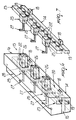
- the problem of cleaning is very important for the optimum operation of the head, since there can be many contamination factors, including: the accidental penetration of external agents which block one or more of the channels 4 that branch out toward the subsequent stages; mixing of different products which are chemically incompatible, triggering polymerization phenomena and consequent blockage of the channels 4; carbonization of the thermoplastic materials used, with a consequent "flue effect”; strong adhesion of the thermoplastic materials to the walls of the duct 2 and of the channels 4, consequently blocking and/or reducing their cross-sections; irreversible polymerization of water-reactive polymers.
- Partial blockage of the duct 2 or of some channels 4 of the head can in fact occur, consequently producing uneven dispensing over the entire adhesive application opening, or some channels 4 can become fully blocked, consequently failing to dispense the adhesive in some regions of the section.
- EP-A-0 539 971 discloses a dispenser which does not contact the substrate wherein the beads of viscous liquid can be dispensed intermittently without the escape of adhesive in string or strand form from the discharge outlet of the nozzle tips when the flow of adhesive is intermittently interrupted.
- thermoplastic material Another drawback of conventional spreading machines is the lack of uniform transverse distribution of the thermoplastic material, caused by the unevenness of the pressures in the channels 4, particularly in very wide heads.
- an external flow equalization device also known as manifold, which consists of a reservoir arranged upstream of the head and connected thereto by means of heated pipes, each of which is fed by a gear pump.
- the aim of the present invention is to solve the above-cited problems, eliminating the drawbacks of the cited prior art, by providing a spreading head which allows to obtain a head which can be easily accessed for cleaning, said head further allowing optimum transverse distribution of the thermoplastic material.
- an object of the present invention is to provide a spreading head which does not require additional use of other machines, such as further pumps or auxiliary reservoirs.
- Another object of the present invention is to provide a spreading head which is structurally simple and has low manufacturing costs.
- the reference numeral 10 designates a spreading head, particularly for spreading thermoplastic material on blanks.
- the head 10 is preferably arranged transversely to the direction of travel of the blanks on which it is necessary to apply, for example, the adhesive, and has a lamination unit 11, an upper clamping block 12 and a lower clamping block, designated by the reference numeral 13.
- the lower clamping block 13 is constituted by a first element, designated by the reference numeral 14 and arranged in a downward region, which advantageously has a rectangular or trapezoidal cross-section and lies transversely to the direction of travel of the blanks.
- a second element 15 is superimposed on the first element 14 and has a lateral surface which preferably mates with the lateral surface of the first element 14.
- a third element is arranged above the second element 15 and also has a lateral surface which advantageously mates with the lateral surface of the second element 15 and can be associated above the lamination unit 11 and the upper clamping block 12.
- the first element 14, the second element 15 and the third element 16 can be detachably secured to each other by virtue of appropriate mechanical connection means, advantageously constituted by a plurality of screws, not shown in the figure, which can be arranged in adapted through holes formed in the first element 14 and the second element 15 and respectively designated by the reference numerals 17a and 17b.
- the through holes 17a and 17b are formed along an axis which is perpendicular to the axis along which lamination of the adhesive on said blanks occurs, and are connected to appropriate complementarily threaded blind holes 17c formed in said third element 16 and adapted to rigidly couple said screws.
- the first element 14 has, on its lateral surface, one or more rear inlets 18; in this embodiment there are two rear inlets, and possibly two other lateral inlets, designated by the reference numeral 19, which allow the entry of the adhesive into a first longitudinal duct 20 of the head 10.
- the first duct 20, advantageously having a rectangular cross-section, is formed in the upper surface of said first element 14 and is closed in an upward region, when the lower clamping block 13 is assembled, by a first lower surface, designated by the reference numeral 21, of the second element 15.
- the first lower surface 21 has, at said first duct 20, a plurality of first through channels, designated by the reference numeral 22, which are arranged vertically and advantageously have a narrower rectangular cross-section so as to allow a first lamination of the adhesive.
- the first channels 22 are connected, in an upward region, to a second duct, designated by the reference numeral 23, which is formed longitudinally on the lower surface of the third element 16 and is appropriately arranged above the first duct 20 and parallel thereto.
- the second duct 23, which also advantageously has a rectangular cross-section, is closed, in a downward region, once the lower clamping block 13 is assembled, by a second upper surface 24 of said second element 15.
- said third element 16 has, at appropriately regular intervals, a series of chambers 25 which are advantageously shaped like a parallelepiped and are adapted to accommodate respective complementarily shaped valves, designated by the reference numeral 26, which can be activated by horizontal translatory motion thereof at right angles to the second duct 23.
- thermoplastic material for example an adhesive
- the thermoplastic material to be spread on the blanks enters the head 10 through one or more of the rear inlets 18 and lateral inlets 19.
- Said inlets convey the adhesive into a first duct 20 which is formed in the first element 14 of the lower clamping block 13 of the head 10.
- the first duct 20 by being connected to a second duct 23 through the first channels 22 of said second element 15, sends the adhesive to the chambers 25.
- the second element 15, which constitutes a perforated plate to be interposed between the two longitudinal ducts, is meant to achieve more uniform dispensing in a transverse direction by balancing the pressures of the adhesive inside the ducts.
- the flow of adhesive to the lamination unit 11 is limited to the intended width by acting on the valves 26 so as to disconnect the unnecessary second channels 27.
- valves 26 The translatory motion of the valves 26 in a horizontal direction inside the head 10 causes said valves 26 to close the respective chambers 25.
- the deactivated valves allow the adhesive to enter the respective second channels 27 and reach, from there, the lamination unit 11.
- a head 1 having been provided which has a lower clamping block 13 which is constituted by a first element, a second element and a third element which are superimposed and can be easily inspected for cleaning.
- the presence of the second element 15 leads to better pressure balancing and therefore to more uniform dispensing in a transverse direction.
- a lower clamping block 113 is constituted by a first element, designated by the reference numeral 114 and arranged in the rear part, which has an advantageously rectangular cross-section and lies transversely to the direction of travel of the blanks.
- a second element designated by the reference numeral 115, is superimposed in front of said first element 114.
- a third element 116 is arranged in front of said second element 115, which is interposed between said first element 114 and said third element 116, having a lateral surface which advantageously mates with the lateral surfaces of said first and third elements, said third element 116 being associable, in an upward region, with a lamination unit 111 and with an upper clamping block, designated by the reference numeral 112.
- the first element 114, the second element 115 and the third element 116 can be detachably secured to each other by virtue of appropriate mechanical connection means, advantageously constituted by a plurality of screws, not shown, which are arranged on an axis which is approximately parallel to the axis along which the thermoplastic material, for example an adhesive, is laminated onto said blanks.
- Said screws can be arranged in appropriate through holes which are formed in said first element 114 and said second element 115 and are designated by the reference numerals 117a and 117b respectively; said screws can further be rigidly coupled in appropriate complementarily threaded blind holes 117c formed in said third element 116.
- the third element 116 has, on its lower surface, one or more inlets 118; this embodiment shows a single inlet, which allows the inflow of the adhesive into a first longitudinal duct 120 of the head 110.
- the first duct 120 which advantageously has a rectangular cross-section, is formed in the rear surface of the third element 116 and is laterally closed, when the lower clamping block 113 is assembled, by a first front surface, designated by the reference numeral 121, of the second element 115.
- the first front surface 121 has, at first duct 120, a plurality of first through channels which are mutually identical, are arranged on a same horizontal plane and are designated by the reference numeral 122; the channels have an advantageously narrower rectangular cross-section so as to allow a first lamination of the adhesive.
- the first channels 122 are connected, in a rear region, to a second duct, designated by the reference numeral 123, which is formed in the front surface of the first element 114 along a longitudinal direction and is conveniently arranged to the rear of, and parallel to, the first duct 120.
- the second duct 123 which also advantageously has a rectangular cross-section, is closed at the front, when the lower clamping block 113 is assembled, by a second rear surface 124 of the second element 115.
- the first element 114 has, at appropriately regular intervals, a series of chambers 125 which are advantageously shaped like a parallelepiped and are adapted to accommodate respective complementarily shaped valves, designated by the reference numeral 126, which can be activated by way of their horizontal translatory motion at right angles to the second duct 123.
- valves 126 are advantageously arranged alternately on staggered planes, so that one is connected in an upward region to the second duct 123 and the other one is connected thereto in a downward region.
- the second channel 127a is connected to a third channel 127b which is formed in the third element 116 and is inclined upward or downward according to the position of the respective chamber 125; the third channel is connected to a fourth channel 127c which is advantageously vertical.
- the fourth channel 127c ends at a third upper surface, designated by the reference numeral 128, of the third element 116 which is associable with a respective surface of the lamination unit 111.
- thermoplastic material for example an adhesive
- the useful width of this type of machine varies, according to the width of the blanks, in a discrete manner with a spacing between one width and the next which is proportional to the dimensions of the valves used.
- the advantage of this second embodiment consists of the fact that it is possible to reduce the spacing between one useful width and the next, since the valves are arranged in a staggered and superimposed configuration.
- valves measuring approximately 30 mm which accordingly entails, in the first embodiment, a spacing of approximately 100 mm between one valve and the next, in the variation described here it is possible to have a smaller spacing, down to 50 mm, with consequent better adaptability to the dimensions of the blanks.
Abstract
Description
- The present invention relates to a spreading head, particularly for spreading thermoplastic material on a blank (see, for example, EP-A-0 539 971, corresponding to the preambles of claims 1 and 2).
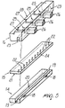
- Conventional spreading heads, shown in Figures 1 and 2, are currently used which are usually arranged transversely to the direction in which the blank travels.
- The head is usually composed of a lamination unit which has a beak-shaped cross-section and an upper clamping block, both not shown in the figures, and an underlying lower clamping block, designated by the reference numeral 1.
- Alternatively, above the lower clamping block 1 there can be a single device which performs the functions of the lamination unit and of the upper clamping block.
- The thermoplastic material (for example adhesives including those known as "hot-melt" or "reactive hot melt" adhesives) is melted beforehand by means of an adapted continuous melting unit or a drum unloader and is then injected into the spreading head by means of gear pumps, not shown.
- Transverse distribution of the adhesive is performed by means of a closed
duct 2, controlled at regularly spaced positions by valves, designated by thereference numeral 3, which determine the passage of the adhesive to a second lamination region, throughchannels 4, and optionally to a third region. -
Channels 4 convey the adhesive directly to the lamination unit, which is directly connected to the blank. - The main drawback of such conventional head is the fact that it has the limitation that its
duct 2, adapted for the first lamination, is of the "closed-section" type and therefore does not allow easy access for complete cleaning. - The problem of cleaning is very important for the optimum operation of the head, since there can be many contamination factors, including: the accidental penetration of external agents which block one or more of the
channels 4 that branch out toward the subsequent stages; mixing of different products which are chemically incompatible, triggering polymerization phenomena and consequent blockage of thechannels 4; carbonization of the thermoplastic materials used, with a consequent "flue effect"; strong adhesion of the thermoplastic materials to the walls of theduct 2 and of thechannels 4, consequently blocking and/or reducing their cross-sections; irreversible polymerization of water-reactive polymers. - The cited drawback related to the impossibility to perform accurate cleaning of the head leads to other subsequent drawbacks.
- Partial blockage of the
duct 2 or of somechannels 4 of the head can in fact occur, consequently producing uneven dispensing over the entire adhesive application opening, or somechannels 4 can become fully blocked, consequently failing to dispense the adhesive in some regions of the section. - These drawbacks are partially solved by the prior art by means of two types of head cleaning: chemical cleaning, by circulating an adapted cleaning product, and mechanical cleaning, directly removing the material that blocks the affected parts.
- The result of chemical cleaning is often only partial, due to the variable aggressiveness of the cleaning product with respect to the contaminant.
- Actually, the second option, i.e., mechanical cleaning, is by far the most effective and widely used, although it too has several problems.
- These problems are related to the fact that the first lamination line can be inspected only from its ends, and this entails considerable difficulty and time to perform mechanical cleaning.
- Some conventional heads are provided with a duct which is obtained by joining contiguous segments: this solution is only a partial remedy to the problem and indeed entails a further complication which affects the manufacturing costs of the entire head. Examples of conventional dispenser for applying viscous liquid such as thermoplastic adhesives are disclosed in the U.S. Patent 5,788,219 and in said EP-A-0 539 971. In US 5,728,219 a modular die is disclosed, and the modularity of the structure of the die allows to vary the die heads which are selected from melt spraying and melt blowing, and linear bead applicators.
- EP-A-0 539 971 discloses a dispenser which does not contact the substrate wherein the beads of viscous liquid can be dispensed intermittently without the escape of adhesive in string or strand form from the discharge outlet of the nozzle tips when the flow of adhesive is intermittently interrupted.
- None of these prior art documents discloses or suggests a device which can be easily accessed for cleaning and which further allows optimum transverse distribution of the thermoplastic material.
- Another drawback of conventional spreading machines is the lack of uniform transverse distribution of the thermoplastic material, caused by the unevenness of the pressures in the
channels 4, particularly in very wide heads. - In order to obviate this drawback, the prior art uses an external flow equalization device, also known as manifold, which consists of a reservoir arranged upstream of the head and connected thereto by means of heated pipes, each of which is fed by a gear pump.
- Said remedial device, however, is very expensive and further requires the additional use of several pumps.
- The aim of the present invention is to solve the above-cited problems, eliminating the drawbacks of the cited prior art, by providing a spreading head which allows to obtain a head which can be easily accessed for cleaning, said head further allowing optimum transverse distribution of the thermoplastic material.
- Within the scope of this aim, an object of the present invention is to provide a spreading head which does not require additional use of other machines, such as further pumps or auxiliary reservoirs.
- Another object of the present invention is to provide a spreading head which is structurally simple and has low manufacturing costs.
- This aim, these and other objects which will become better apparent hereinafter are achieved by a spreading head, according to
claim 1 or 2. - Further features of the invention are disclosed in the
dependent claims 3 to 21. - Further characteristics and advantages of the present invention will become better apparent from the following detailed description of a particular embodiment thereof, illustrated only by way of non-limitative example in the accompanying drawings, wherein:
- Figure 1 is a perspective view of the lower clamping block of a conventional head;
- Figure 2 is a perspective view of the path of the flows of thermoplastic material in ducts and valves of a conventional lower clamping block;
- Figure 3 is a side view of a head according to the invention;
- Figure 4 is a side view of the path of the flows of thermoplastic material in the ducts of a head according to the invention;
- Figure 5 is an exploded perspective view of the lower clamping block according to the invention;
- Figure 6 is a perspective view of the lower clamping block of a head according to the invention;
- Figure 7 is a perspective view of the path of the flows of thermoplastic material in the ducts and valves of a lower clamping block of a head according to the invention;
- Figure 8 is a side view of a different embodiment of the head according to the invention;
- Figure 9 is a side view of the path of the flows of thermoplastic material in the ducts of a different embodiment of the head according to the invention;
- Figure 10 is an exploded perspective view of a different embodiment of the lower clamping block according to the invention.
-
- With reference to the above-cited figures, the
reference numeral 10 designates a spreading head, particularly for spreading thermoplastic material on blanks. - The
head 10 is preferably arranged transversely to the direction of travel of the blanks on which it is necessary to apply, for example, the adhesive, and has alamination unit 11, anupper clamping block 12 and a lower clamping block, designated by thereference numeral 13. - The
lower clamping block 13 is constituted by a first element, designated by thereference numeral 14 and arranged in a downward region, which advantageously has a rectangular or trapezoidal cross-section and lies transversely to the direction of travel of the blanks. - A
second element 15 is superimposed on thefirst element 14 and has a lateral surface which preferably mates with the lateral surface of thefirst element 14. - A third element, designated by the
reference numeral 16, is arranged above thesecond element 15 and also has a lateral surface which advantageously mates with the lateral surface of thesecond element 15 and can be associated above thelamination unit 11 and theupper clamping block 12. - The
first element 14, thesecond element 15 and thethird element 16 can be detachably secured to each other by virtue of appropriate mechanical connection means, advantageously constituted by a plurality of screws, not shown in the figure, which can be arranged in adapted through holes formed in thefirst element 14 and thesecond element 15 and respectively designated by thereference numerals 17a and 17b. - The through
holes 17a and 17b are formed along an axis which is perpendicular to the axis along which lamination of the adhesive on said blanks occurs, and are connected to appropriate complementarily threadedblind holes 17c formed in saidthird element 16 and adapted to rigidly couple said screws. - The
first element 14 has, on its lateral surface, one or morerear inlets 18; in this embodiment there are two rear inlets, and possibly two other lateral inlets, designated by thereference numeral 19, which allow the entry of the adhesive into a firstlongitudinal duct 20 of thehead 10. - The
first duct 20, advantageously having a rectangular cross-section, is formed in the upper surface of saidfirst element 14 and is closed in an upward region, when thelower clamping block 13 is assembled, by a first lower surface, designated by thereference numeral 21, of thesecond element 15. - The first
lower surface 21 has, at saidfirst duct 20, a plurality of first through channels, designated by thereference numeral 22, which are arranged vertically and advantageously have a narrower rectangular cross-section so as to allow a first lamination of the adhesive. - The
first channels 22 are connected, in an upward region, to a second duct, designated by thereference numeral 23, which is formed longitudinally on the lower surface of thethird element 16 and is appropriately arranged above thefirst duct 20 and parallel thereto. - The
second duct 23, which also advantageously has a rectangular cross-section, is closed, in a downward region, once thelower clamping block 13 is assembled, by a secondupper surface 24 of saidsecond element 15. - Along said
second duct 23, and above it, saidthird element 16 has, at appropriately regular intervals, a series ofchambers 25 which are advantageously shaped like a parallelepiped and are adapted to accommodate respective complementarily shaped valves, designated by thereference numeral 26, which can be activated by horizontal translatory motion thereof at right angles to thesecond duct 23. - A second channel, designated by the
reference numeral 27, branches out from each one of thechambers 25; said second channel is advantageously L-or S-shaped and is connected to a third upper surface, designated by thereference numeral 28, on which an adapted surface of saidlamination unit 11 is associated. - Operation is therefore as follows: with reference to Figures 3 onward, the thermoplastic material, for example an adhesive, to be spread on the blanks enters the
head 10 through one or more of therear inlets 18 andlateral inlets 19. - Said inlets convey the adhesive into a
first duct 20 which is formed in thefirst element 14 of thelower clamping block 13 of thehead 10. Thefirst duct 20, by being connected to asecond duct 23 through thefirst channels 22 of saidsecond element 15, sends the adhesive to thechambers 25. - Use of the
second element 15, which constitutes a perforated plate to be interposed between the two longitudinal ducts, is meant to achieve more uniform dispensing in a transverse direction by balancing the pressures of the adhesive inside the ducts. - If the head is used on blanks which are not as wide as said head, the flow of adhesive to the
lamination unit 11 is limited to the intended width by acting on thevalves 26 so as to disconnect the unnecessarysecond channels 27. - The translatory motion of the
valves 26 in a horizontal direction inside thehead 10 causes saidvalves 26 to close therespective chambers 25. - The deactivated valves allow the adhesive to enter the respective
second channels 27 and reach, from there, thelamination unit 11. - The cleaning of said head is considerably faster and more accurate, since the
lower clamping block 13, affected by the presence of the adhesive and therefore subject to blockage, can be easily disassembled into its three components, all of which have easily accessible chambers and ducts. - It has thus been observed that the invention has achieved the intended aim and objects, a head 1 having been provided which has a
lower clamping block 13 which is constituted by a first element, a second element and a third element which are superimposed and can be easily inspected for cleaning. - At the same time, the presence of the
second element 15 leads to better pressure balancing and therefore to more uniform dispensing in a transverse direction. - The invention is of course susceptible of numerous modifications and variations, if within the scope of invention as defined in the claims.
- Thus, for example, it is possible to provide a different embodiment of the invention in which a lower clamping block 113 is constituted by a first element, designated by the
reference numeral 114 and arranged in the rear part, which has an advantageously rectangular cross-section and lies transversely to the direction of travel of the blanks. - A second element, designated by the
reference numeral 115, is superimposed in front of saidfirst element 114. - A
third element 116 is arranged in front of saidsecond element 115, which is interposed between saidfirst element 114 and saidthird element 116, having a lateral surface which advantageously mates with the lateral surfaces of said first and third elements, saidthird element 116 being associable, in an upward region, with alamination unit 111 and with an upper clamping block, designated by thereference numeral 112. - The
first element 114, thesecond element 115 and thethird element 116 can be detachably secured to each other by virtue of appropriate mechanical connection means, advantageously constituted by a plurality of screws, not shown, which are arranged on an axis which is approximately parallel to the axis along which the thermoplastic material, for example an adhesive, is laminated onto said blanks. - Said screws can be arranged in appropriate through holes which are formed in said
first element 114 and saidsecond element 115 and are designated by thereference numerals 117a and 117b respectively; said screws can further be rigidly coupled in appropriate complementarily threadedblind holes 117c formed in saidthird element 116. - The
third element 116 has, on its lower surface, one ormore inlets 118; this embodiment shows a single inlet, which allows the inflow of the adhesive into a firstlongitudinal duct 120 of thehead 110. - The
first duct 120, which advantageously has a rectangular cross-section, is formed in the rear surface of thethird element 116 and is laterally closed, when the lower clamping block 113 is assembled, by a first front surface, designated by thereference numeral 121, of thesecond element 115. - The first
front surface 121 has, atfirst duct 120, a plurality of first through channels which are mutually identical, are arranged on a same horizontal plane and are designated by thereference numeral 122; the channels have an advantageously narrower rectangular cross-section so as to allow a first lamination of the adhesive. - The
first channels 122 are connected, in a rear region, to a second duct, designated by thereference numeral 123, which is formed in the front surface of thefirst element 114 along a longitudinal direction and is conveniently arranged to the rear of, and parallel to, thefirst duct 120. - The
second duct 123, which also advantageously has a rectangular cross-section, is closed at the front, when the lower clamping block 113 is assembled, by a secondrear surface 124 of thesecond element 115. - Along the
second duct 123, and to the rear of it, thefirst element 114 has, at appropriately regular intervals, a series ofchambers 125 which are advantageously shaped like a parallelepiped and are adapted to accommodate respective complementarily shaped valves, designated by thereference numeral 126, which can be activated by way of their horizontal translatory motion at right angles to thesecond duct 123. - The
valves 126 are advantageously arranged alternately on staggered planes, so that one is connected in an upward region to thesecond duct 123 and the other one is connected thereto in a downward region. - In this manner a more compact device is obtained which has a smaller spacing between one valve and the next.
- A second channel, designated by the
reference numeral 127a, extends from each one of saidchambers 125, is advantageously horizontal and passes, along the same axis, through the first andsecond elements - The
second channel 127a is connected to athird channel 127b which is formed in thethird element 116 and is inclined upward or downward according to the position of therespective chamber 125; the third channel is connected to afourth channel 127c which is advantageously vertical. - The
fourth channel 127c ends at a third upper surface, designated by thereference numeral 128, of thethird element 116 which is associable with a respective surface of thelamination unit 111. - The operation of this embodiment is fully similar to the operation of the previously described one, since the thermoplastic material, for example an adhesive, by entering from the
lower inlet 118, passes through afirst duct 120,first channels 122 and asecond duct 123, distributing itself uniformly, if allowed by the position of thevalves 126, in thechambers 125. - From there, through second channels 127, the adhesive reaches a
lamination unit 111. - The useful width of this type of machine varies, according to the width of the blanks, in a discrete manner with a spacing between one width and the next which is proportional to the dimensions of the valves used.
- The advantage of this second embodiment consists of the fact that it is possible to reduce the spacing between one useful width and the next, since the valves are arranged in a staggered and superimposed configuration.
- In this manner, if for example one uses valves measuring approximately 30 mm, which accordingly entails, in the first embodiment, a spacing of approximately 100 mm between one valve and the next, in the variation described here it is possible to have a smaller spacing, down to 50 mm, with consequent better adaptability to the dimensions of the blanks.
- This solution, too, therefore achieves the intended aim and objects.
- The materials used, as well as the dimensions that constitute the individual components of the invention, may of course be more pertinent according to specific requirements.
- Where technical features mentioned in any claim are followed by reference signs, those reference signs have been included for the sole purpose of increasing the intelligibility of the claims and accordingly, such reference signs do not have any limiting effect on the interpretation of each element identified by way of example by such reference signs.
Claims (21)
- A spreading head, particularly for spreading thermoplastic material on a blank, comprising a lower clamping block (13, 113), a lamination unit (11, 111) and an upper clamping block (12, 112), which is arranged transversely to the direction of travel of said blank, characterized in that said lower clamping block (13, 113) is constituted by a first element (14, 114) and a third element (16, 116) which can be detachably coupled to each other by virtue of mechanical connection means, said first element (14, 114) having a first longitudinal duct (20, 120) which is connected to a second longitudinal duct (23, 123) formed in said third element (16, 116).
- A spreading head (10), particularly for uniformly spreading thermoplastic material on a blank, comprising a lower clamping block (13, 113), a lamination unit (11, 111) and an upper clamping block (12, 112), which is arranged transversely to the direction of travel of said blank, characterized in that said lower clamping block (13, 113) is constituted by a first element (14, 114), a second element (15, 115), and a third element (16, 116) which are mutually detachably coupled by virtue of mechanical connection means, said first element (14, 114) having a first longitudinal duct (20, 120) which is connected to a plurality of first channels (22, 122) formed in said second element (15, 115), said first channels (22), which are through channels and are arranged vertically, having a cross-section with smaller dimensions with respect to said longitudinal duct (20, 120) so as to allow a first lamination of the thermoplastic material and to perform a pressure balancing of the molted fluid in a transverse direction in order to achieve a uniform dispensing of thermoplastic material in a transverse direction, said third element (16, 116) having a second longitudinal duct (23, 123) which is connected to said first channels (22, 122) and to a series of chambers (25, 125) each chamber being associated with a second channel (27, 127), said second channel (27, 127) being associated with said lamination unit (11, 111) in order to uniformly spreading said thermoplastic material on a blank.
- The head according to claim 2, characterized in that said first element (14) has a rectangular or trapezoidal cross-section and a lateral surface which preferably mates with the lateral surface of said second element (15) which is arranged above said first element (14), said third element (16) being arranged above said second element (14) and also having a lateral surface which advantageously mates with the lateral surface of said second element (15).
- The head according to claim 3, characterized in that said mechanical connection means for the mutual detachable coupling of said first (14), second (15) and third (16) elements are constituted by a plurality of screws which can be arranged in adapted through holes (17a, 17b) formed in said first (14) and second (15) elements along an axis which is perpendicular to the axis along which lamination of the thermoplastic material on said blanks occurs, said screws being rigidly fixable in appropriate complementarily shaped blind holes (17c) formed in said third element (16).
- The head according to any of the preceding claims 2 to 4, characterized in that said first element (14) has one or more inlets (18, 19) for the thermoplastic material, said inlets being preferably arranged on the lateral surface in a rear position and/or in a lateral position.
- The head according to claim 5, characterized in that said inlets (18, 19) are connected to said first duct (20), formed in the upper surface of said first element (14) with a cross-section which is advantageously rectangular, said first duct (20) being closed in an upward region, when the lower clamping block (13) is assembled, by a first lower surface (21) of said second element (15).
- The head according to claim 6, characterized in that said first channels (22), which are through channels and are arranged vertically, are formed at said first lower surface (21) and have a an advantageously rectangular cross-section with smaller dimensions than the rectangular cross-section of the first longitudinal duct (20, 120) so as to allow a first lamination of the thermoplastic material.
- The head according to claim 7, characterized in that said first channels (22) are connected, in an upward region, to said second duct (23), which is formed longitudinally on the lower surface (21) of said third element (16) and is appropriately arranged above said first duct (20) and parallel thereto.
- The head according to claim 6, characterized in that said second duct (23), which also advantageously has a rectangular cross-section, is closed in a downward region, when the lower clamping block (13) is assembled, by a second upper surface (24) of said second element (15).
- The head according to any of the preceding claims 2 to 9, characterized in that it has, along and above said second duct (23), said series of chambers (25) are arranged at appropriately regular intervals, said chambers (25) being advantageously shaped like a parallelepiped and being adapted to accommodate respective complementarily shaped valves (26) which can be activated by virtue of a horizontal translatory motion thereof at right angles to said second duct (23).
- The head according to claim 2, characterized in that a second channel (27) is associated with each one of said chambers (25), said channel being advantageously L-shaped or S-shaped and being connected to a third upper surface (28) on which an adapted surface of said lamination unit (11) is associated.
- The head according to claim 2, characterized in that said first element (114) is arranged in the rear part of said lower clamping block (113), said second element (115) is arranged in front of said first element (114), said third element (116) is arranged in front of said second element (115) which has a lateral surface which advantageously mates with the lateral surfaces of said first (114) and third (116) elements and is interposed between them, said first (114), second (115) and third elements (116) being mutually lockable by means of screws arranged along an axis which is approximately parallel to the lamination axis. 12
- The head according to claim 12, characterized in that said third element (116) has, preferably on its lower surface, one or more inlets (118) for the thermoplastic material. 13
- The head according to claim 13, characterized in that said inlets (118) are connected to said first duct (120) which advantageously has a rectangular cross-section and is arranged longitudinally, said first duct (120) being formed in the rear surface of said third element (116) and being laterally closed, when the lower clamping block (113) is assembled, by a first front surface (121) of said second element (115).
- The head according to claim 14, characterized in that said first front surface (121) has said plurality of first through channels (122) which are mutually identical, are arranged on a same horizontal plane and have an advantageously rectangular cross-section which is narrower than the rectangular cross-section of the first longitudinal duct (20, 120) so as to allow a first lamination of the thermoplastic material.
- The head according to anyone of claims 12 to 15, characterized in that said first channels (122) are connected in a rear region to said second duct (123) which is formed in the front surface of said first element (114) along a longitudinal direction and is advantageously arranged to the rear of said first duct (120) and parallel thereto.
- The head according to claim 16, characterized in that said second duct (123), which also advantageously has a rectangular cross-section, is closed at the front, when the lower clamping block (113) is assembled, by a second rear surface (124) of said second element (115).
- The head according to anyone of claims 12 to 17, characterized in that said series of chambers (125) are arranged at appropriately regular intervals, said chambers (125) being advantageously shaped like a parallelepiped and being adapted to accommodate respective complementarily shaped valves (126) which can be activated by horizontal translatory motion thereof at right angles to said second duct (123).
- The head according to claim 18, characterized in that said valves (126) are advantageously arranged alternately on staggered planes, so that one is connected in an upward region to said second duct (123) and the other valve is connected thereto in a downward region.
- The head according to claim 18 or 19, characterized in that a second channel (127a) is associated with each one of said chambers (125), is advantageously horizontal, and is formed along the same axis in said first (114) and second elements (115), said second channel (127a) being connected to a third channel (127b) which is formed in said third element (116) and is inclined upward or downward according to the position of the respective chamber (125).
- The head according to claim 20, characterized in that said third channel (127b) is connected to a fourth channel (127c) which is advantageously vertical and exits at a third upper surface (128) of said third element (116) which is associable with a respective surface of said lamination unit (111).
Applications Claiming Priority (2)
| Application Number | Priority Date | Filing Date | Title |
|---|---|---|---|
| ITTV990124 | 1999-11-16 | ||
| IT1999TV000124A IT1311872B1 (en) | 1999-11-16 | 1999-11-16 | COATING HEAD, PARTICULARLY FOR THERMOPLASTIC MATERIAL. |
Publications (2)
| Publication Number | Publication Date |
|---|---|
| EP1101537A1 EP1101537A1 (en) | 2001-05-23 |
| EP1101537B1 true EP1101537B1 (en) | 2005-06-01 |
Family
ID=11420701
Family Applications (1)
| Application Number | Title | Priority Date | Filing Date |
|---|---|---|---|
| EP00123500A Expired - Lifetime EP1101537B1 (en) | 1999-11-16 | 2000-11-08 | Spreading head, particularly for thermoplastic material |
Country Status (5)
| Country | Link |
|---|---|
| EP (1) | EP1101537B1 (en) |
| AT (1) | ATE296683T1 (en) |
| DE (1) | DE60020496T2 (en) |
| ES (1) | ES2241537T3 (en) |
| IT (1) | IT1311872B1 (en) |
Families Citing this family (6)
| Publication number | Priority date | Publication date | Assignee | Title |
|---|---|---|---|---|
| IT1311872B1 (en) | 1999-11-16 | 2002-03-19 | Hip High Ind Performances Srl | COATING HEAD, PARTICULARLY FOR THERMOPLASTIC MATERIAL. |
| ITTV20040020A1 (en) * | 2004-03-02 | 2004-06-02 | Hip Srl High Ind Performance S | COATING DEVICE, PARTICULARLY FOR THE DEPOSITION OF ADHESIVES AND / OR POLYMERIC MATERIALS IN LIQUID DISPERSION |
| ITTV20060123A1 (en) * | 2006-07-17 | 2008-01-18 | Hip Mitsu Srl | CUTTING HEAD STRUCTURE, PARTICULARLY OF ONE OR MORE ADHESIVES OR MIXTURES OF STICKERS |
| ITTV20060124A1 (en) * | 2006-07-17 | 2008-01-18 | Hip Mitsu Srl | CUTTING HEAD STRUCTURE, PARTICULARLY OF ONE OR MORE ADHESIVES OR MIXTURES OF STICKERS |
| DE102007052996A1 (en) * | 2007-11-05 | 2009-05-07 | Beiersdorf Ag | Coating tool for coating flat material has at least one jet lip with distribution system for supplied liquid coating material |
| DE202010013054U1 (en) * | 2010-12-03 | 2012-03-05 | Baumer Hhs Gmbh | Device for applying viscous media |
Family Cites Families (6)
| Publication number | Priority date | Publication date | Assignee | Title |
|---|---|---|---|---|
| US5067432A (en) * | 1990-05-23 | 1991-11-26 | Extrusion Dies, Inc. | Replaceable wiping insert for slot die head |
| CA2081499A1 (en) * | 1991-11-01 | 1993-05-02 | Wesley Fort | Method and apparatus for dispensing multiple beads of viscous liquid |
| DE59305026D1 (en) * | 1992-07-03 | 1997-02-20 | Friz Maschinenbau Gmbh | Device for applying adhesive |
| JP2932163B2 (en) * | 1994-11-28 | 1999-08-09 | 株式会社ヒラノテクシード | Double side coating type coating equipment |
| US5728219A (en) * | 1995-09-22 | 1998-03-17 | J&M Laboratories, Inc. | Modular die for applying adhesives |
| IT1311872B1 (en) | 1999-11-16 | 2002-03-19 | Hip High Ind Performances Srl | COATING HEAD, PARTICULARLY FOR THERMOPLASTIC MATERIAL. |
-
1999
- 1999-11-16 IT IT1999TV000124A patent/IT1311872B1/en active
-
2000
- 2000-11-08 ES ES00123500T patent/ES2241537T3/en not_active Expired - Lifetime
- 2000-11-08 AT AT00123500T patent/ATE296683T1/en not_active IP Right Cessation
- 2000-11-08 EP EP00123500A patent/EP1101537B1/en not_active Expired - Lifetime
- 2000-11-08 DE DE60020496T patent/DE60020496T2/en not_active Expired - Lifetime
Also Published As
| Publication number | Publication date |
|---|---|
| IT1311872B1 (en) | 2002-03-19 |
| DE60020496T2 (en) | 2005-11-10 |
| DE60020496D1 (en) | 2005-07-07 |
| ES2241537T3 (en) | 2005-11-01 |
| ITTV990124A1 (en) | 2001-05-16 |
| ATE296683T1 (en) | 2005-06-15 |
| EP1101537A1 (en) | 2001-05-23 |
Similar Documents
| Publication | Publication Date | Title |
|---|---|---|
| US5636790A (en) | Fluid applicator | |
| US5000112A (en) | Apparatus for the surface coating of glue | |
| CA1291679C (en) | Method and apparatus for applying narrow, closely spaced beads of viscous liquid to a substrate | |
| US5992453A (en) | Flow-dividing arrangement | |
| US6540831B1 (en) | Method and apparatus for applying a controlled pattern of fibrous material to a moving substrate | |
| EP2473288B1 (en) | Metering system for simultaneously dispensing two different adhesives from a single metering device or applicator onto a common substrate | |
| CN109641233A (en) | Applicator with current divider plate | |
| EP1880773B1 (en) | Spreading head particularly for spreading one or more adhesives or mixtures of adhesives | |
| US7152815B2 (en) | Dispensing system, nozzle and method for independently dispensing and controlling liquid | |
| JP2005313170A (en) | Liquid dispenser having individualized process air control part | |
| EP1166890B1 (en) | Split output adhesive nozzle assembly | |
| US5740963A (en) | Self-sealing slot nozzle die | |
| EP1101537B1 (en) | Spreading head, particularly for thermoplastic material | |
| US5871585A (en) | Apparatus for applying a fluid to a moving web of material | |
| US20140065305A1 (en) | Method of applying thermoplastic liquid onto a substrate | |
| EP1588778A2 (en) | Angled manifold and dispensing apparatus | |
| KR20060120564A (en) | Apparatus for depositing fluid material onto a substrate | |
| US5851566A (en) | Applicator die | |
| EP0907422B1 (en) | Sealing system for improved applicator die | |
| JP3338693B2 (en) | Die set for stripe coating and method thereof | |
| EP1085946B1 (en) | Spreader for spreading a fluid, such as an adhesive | |
| US20010042507A1 (en) | Device for applying adhesives | |
| US7052549B2 (en) | Dispensing apparatus and manifold having an adhesive catch groove | |
| AU775335B2 (en) | Fluid applicator | |
| AU748546B2 (en) | Fluid applicator |
Legal Events
| Date | Code | Title | Description |
|---|---|---|---|
| PUAI | Public reference made under article 153(3) epc to a published international application that has entered the european phase |
Free format text: ORIGINAL CODE: 0009012 |
|
| AK | Designated contracting states |
Kind code of ref document: A1 Designated state(s): AT BE CH CY DE DK ES FI FR GB GR IE IT LI LU MC NL PT SE TR |
|
| AX | Request for extension of the european patent |
Free format text: AL;LT;LV;MK;RO;SI |
|
| 17P | Request for examination filed |
Effective date: 20011122 |
|
| AKX | Designation fees paid |
Free format text: AT BE CH CY DE DK ES FI FR GB GR IE IT LI LU MC NL PT SE TR |
|
| 17Q | First examination report despatched |
Effective date: 20031216 |
|
| GRAP | Despatch of communication of intention to grant a patent |
Free format text: ORIGINAL CODE: EPIDOSNIGR1 |
|
| GRAS | Grant fee paid |
Free format text: ORIGINAL CODE: EPIDOSNIGR3 |
|
| GRAA | (expected) grant |
Free format text: ORIGINAL CODE: 0009210 |
|
| RAP1 | Party data changed (applicant data changed or rights of an application transferred) |
Owner name: HIP-MITSU S.R.L. |
|
| AK | Designated contracting states |
Kind code of ref document: B1 Designated state(s): AT BE CH CY DE DK ES FI FR GB GR IE IT LI LU MC NL PT SE TR |
|
| PG25 | Lapsed in a contracting state [announced via postgrant information from national office to epo] |
Ref country code: FI Free format text: LAPSE BECAUSE OF FAILURE TO SUBMIT A TRANSLATION OF THE DESCRIPTION OR TO PAY THE FEE WITHIN THE PRESCRIBED TIME-LIMIT Effective date: 20050601 Ref country code: BE Free format text: LAPSE BECAUSE OF FAILURE TO SUBMIT A TRANSLATION OF THE DESCRIPTION OR TO PAY THE FEE WITHIN THE PRESCRIBED TIME-LIMIT Effective date: 20050601 Ref country code: AT Free format text: LAPSE BECAUSE OF FAILURE TO SUBMIT A TRANSLATION OF THE DESCRIPTION OR TO PAY THE FEE WITHIN THE PRESCRIBED TIME-LIMIT Effective date: 20050601 Ref country code: TR Free format text: LAPSE BECAUSE OF FAILURE TO SUBMIT A TRANSLATION OF THE DESCRIPTION OR TO PAY THE FEE WITHIN THE PRESCRIBED TIME-LIMIT Effective date: 20050601 |
|
| REG | Reference to a national code |
Ref country code: GB Ref legal event code: FG4D |
|
| REG | Reference to a national code |
Ref country code: CH Ref legal event code: EP |
|
| REG | Reference to a national code |
Ref country code: IE Ref legal event code: FG4D |
|
| REF | Corresponds to: |
Ref document number: 60020496 Country of ref document: DE Date of ref document: 20050707 Kind code of ref document: P |
|
| REG | Reference to a national code |
Ref country code: CH Ref legal event code: NV Representative=s name: MARK-PAT MODIANO S.A. |
|
| PG25 | Lapsed in a contracting state [announced via postgrant information from national office to epo] |
Ref country code: DK Free format text: LAPSE BECAUSE OF FAILURE TO SUBMIT A TRANSLATION OF THE DESCRIPTION OR TO PAY THE FEE WITHIN THE PRESCRIBED TIME-LIMIT Effective date: 20050901 Ref country code: GR Free format text: LAPSE BECAUSE OF FAILURE TO SUBMIT A TRANSLATION OF THE DESCRIPTION OR TO PAY THE FEE WITHIN THE PRESCRIBED TIME-LIMIT Effective date: 20050901 Ref country code: SE Free format text: LAPSE BECAUSE OF FAILURE TO SUBMIT A TRANSLATION OF THE DESCRIPTION OR TO PAY THE FEE WITHIN THE PRESCRIBED TIME-LIMIT Effective date: 20050901 |
|
| REG | Reference to a national code |
Ref country code: ES Ref legal event code: FG2A Ref document number: 2241537 Country of ref document: ES Kind code of ref document: T3 |
|
| PG25 | Lapsed in a contracting state [announced via postgrant information from national office to epo] |
Ref country code: PT Free format text: LAPSE BECAUSE OF FAILURE TO SUBMIT A TRANSLATION OF THE DESCRIPTION OR TO PAY THE FEE WITHIN THE PRESCRIBED TIME-LIMIT Effective date: 20051103 |
|
| PG25 | Lapsed in a contracting state [announced via postgrant information from national office to epo] |
Ref country code: CY Free format text: LAPSE BECAUSE OF FAILURE TO SUBMIT A TRANSLATION OF THE DESCRIPTION OR TO PAY THE FEE WITHIN THE PRESCRIBED TIME-LIMIT Effective date: 20051108 Ref country code: IE Free format text: LAPSE BECAUSE OF NON-PAYMENT OF DUE FEES Effective date: 20051108 |
|
| PG25 | Lapsed in a contracting state [announced via postgrant information from national office to epo] |
Ref country code: MC Free format text: LAPSE BECAUSE OF NON-PAYMENT OF DUE FEES Effective date: 20051130 Ref country code: LU Free format text: LAPSE BECAUSE OF NON-PAYMENT OF DUE FEES Effective date: 20051130 |
|
| ET | Fr: translation filed | ||
| PLBE | No opposition filed within time limit |
Free format text: ORIGINAL CODE: 0009261 |
|
| STAA | Information on the status of an ep patent application or granted ep patent |
Free format text: STATUS: NO OPPOSITION FILED WITHIN TIME LIMIT |
|
| 26N | No opposition filed |
Effective date: 20060302 |
|
| REG | Reference to a national code |
Ref country code: IE Ref legal event code: MM4A |
|
| REG | Reference to a national code |
Ref country code: DE Ref legal event code: R082 Ref document number: 60020496 Country of ref document: DE Representative=s name: ANDRAE WESTENDORP PATENTANWAELTE PARTNERSCHAFT, DE Ref country code: DE Ref legal event code: R082 Ref document number: 60020496 Country of ref document: DE Representative=s name: SCHIEBER FARAGO PATENTANWAELTE, DE Ref country code: DE Ref legal event code: R082 Ref document number: 60020496 Country of ref document: DE Representative=s name: FARAGO PATENTANWALTS- UND RECHTSANWALTSGESELLS, DE |
|
| REG | Reference to a national code |
Ref country code: FR Ref legal event code: PLFP Year of fee payment: 16 |
|
| REG | Reference to a national code |
Ref country code: FR Ref legal event code: PLFP Year of fee payment: 17 |
|
| REG | Reference to a national code |
Ref country code: FR Ref legal event code: PLFP Year of fee payment: 18 |
|
| PGFP | Annual fee paid to national office [announced via postgrant information from national office to epo] |
Ref country code: FR Payment date: 20171031 Year of fee payment: 18 |
|
| REG | Reference to a national code |
Ref country code: DE Ref legal event code: R082 Ref document number: 60020496 Country of ref document: DE Representative=s name: SCHIEBER FARAGO PATENTANWAELTE, DE Ref country code: DE Ref legal event code: R082 Ref document number: 60020496 Country of ref document: DE Representative=s name: FARAGO PATENTANWALTS- UND RECHTSANWALTSGESELLS, DE Ref country code: DE Ref legal event code: R082 Ref document number: 60020496 Country of ref document: DE Representative=s name: FARAGO PATENTANWAELTE, DE |
|
| PGFP | Annual fee paid to national office [announced via postgrant information from national office to epo] |
Ref country code: GB Payment date: 20171123 Year of fee payment: 18 |
|
| REG | Reference to a national code |
Ref country code: DE Ref legal event code: R082 Ref document number: 60020496 Country of ref document: DE Representative=s name: FARAGO PATENTANWALTS- UND RECHTSANWALTSGESELLS, DE Ref country code: DE Ref legal event code: R082 Ref document number: 60020496 Country of ref document: DE Representative=s name: FARAGO PATENTANWAELTE, DE |
|
| PGFP | Annual fee paid to national office [announced via postgrant information from national office to epo] |
Ref country code: NL Payment date: 20181127 Year of fee payment: 19 |
|
| PGFP | Annual fee paid to national office [announced via postgrant information from national office to epo] |
Ref country code: DE Payment date: 20181123 Year of fee payment: 19 |
|
| PGFP | Annual fee paid to national office [announced via postgrant information from national office to epo] |
Ref country code: ES Payment date: 20181213 Year of fee payment: 19 Ref country code: IT Payment date: 20181116 Year of fee payment: 19 |
|
| PGFP | Annual fee paid to national office [announced via postgrant information from national office to epo] |
Ref country code: CH Payment date: 20190124 Year of fee payment: 19 |
|
| GBPC | Gb: european patent ceased through non-payment of renewal fee |
Effective date: 20181108 |
|
| PG25 | Lapsed in a contracting state [announced via postgrant information from national office to epo] |
Ref country code: FR Free format text: LAPSE BECAUSE OF NON-PAYMENT OF DUE FEES Effective date: 20181130 |
|
| PG25 | Lapsed in a contracting state [announced via postgrant information from national office to epo] |
Ref country code: GB Free format text: LAPSE BECAUSE OF NON-PAYMENT OF DUE FEES Effective date: 20181108 |
|
| REG | Reference to a national code |
Ref country code: DE Ref legal event code: R119 Ref document number: 60020496 Country of ref document: DE |
|
| REG | Reference to a national code |
Ref country code: CH Ref legal event code: PL |
|
| REG | Reference to a national code |
Ref country code: NL Ref legal event code: MM Effective date: 20191201 |
|
| PG25 | Lapsed in a contracting state [announced via postgrant information from national office to epo] |
Ref country code: CH Free format text: LAPSE BECAUSE OF NON-PAYMENT OF DUE FEES Effective date: 20191130 Ref country code: LI Free format text: LAPSE BECAUSE OF NON-PAYMENT OF DUE FEES Effective date: 20191130 |
|
| PG25 | Lapsed in a contracting state [announced via postgrant information from national office to epo] |
Ref country code: NL Free format text: LAPSE BECAUSE OF NON-PAYMENT OF DUE FEES Effective date: 20191201 |
|
| PG25 | Lapsed in a contracting state [announced via postgrant information from national office to epo] |
Ref country code: IT Free format text: LAPSE BECAUSE OF NON-PAYMENT OF DUE FEES Effective date: 20191108 Ref country code: DE Free format text: LAPSE BECAUSE OF NON-PAYMENT OF DUE FEES Effective date: 20200603 |
|
| REG | Reference to a national code |
Ref country code: ES Ref legal event code: FD2A Effective date: 20210414 |
|
| PG25 | Lapsed in a contracting state [announced via postgrant information from national office to epo] |
Ref country code: ES Free format text: LAPSE BECAUSE OF NON-PAYMENT OF DUE FEES Effective date: 20191109 |