EP1100731B1 - Trifold dispenser blank for tape strip pads - Google Patents
Trifold dispenser blank for tape strip pads Download PDFInfo
- Publication number
- EP1100731B1 EP1100731B1 EP99902999A EP99902999A EP1100731B1 EP 1100731 B1 EP1100731 B1 EP 1100731B1 EP 99902999 A EP99902999 A EP 99902999A EP 99902999 A EP99902999 A EP 99902999A EP 1100731 B1 EP1100731 B1 EP 1100731B1
- Authority
- EP
- European Patent Office
- Prior art keywords
- section
- central section
- central
- dispenser
- dispenser blank
- Prior art date
- Legal status (The legal status is an assumption and is not a legal conclusion. Google has not performed a legal analysis and makes no representation as to the accuracy of the status listed.)
- Expired - Lifetime
Links
Images

Classifications
-
- B—PERFORMING OPERATIONS; TRANSPORTING
- B65—CONVEYING; PACKING; STORING; HANDLING THIN OR FILAMENTARY MATERIAL
- B65H—HANDLING THIN OR FILAMENTARY MATERIAL, e.g. SHEETS, WEBS, CABLES
- B65H35/00—Delivering articles from cutting or line-perforating machines; Article or web delivery apparatus incorporating cutting or line-perforating devices, e.g. adhesive tape dispensers
- B65H35/04—Delivering articles from cutting or line-perforating machines; Article or web delivery apparatus incorporating cutting or line-perforating devices, e.g. adhesive tape dispensers from or with transverse cutters or perforators
- B65H35/06—Delivering articles from cutting or line-perforating machines; Article or web delivery apparatus incorporating cutting or line-perforating devices, e.g. adhesive tape dispensers from or with transverse cutters or perforators from or with blade, e.g. shear-blade, cutters or perforators
-
- B—PERFORMING OPERATIONS; TRANSPORTING
- B65—CONVEYING; PACKING; STORING; HANDLING THIN OR FILAMENTARY MATERIAL
- B65D—CONTAINERS FOR STORAGE OR TRANSPORT OF ARTICLES OR MATERIALS, e.g. BAGS, BARRELS, BOTTLES, BOXES, CANS, CARTONS, CRATES, DRUMS, JARS, TANKS, HOPPERS, FORWARDING CONTAINERS; ACCESSORIES, CLOSURES, OR FITTINGS THEREFOR; PACKAGING ELEMENTS; PACKAGES
- B65D83/00—Containers or packages with special means for dispensing contents
- B65D83/08—Containers or packages with special means for dispensing contents for dispensing thin flat articles in succession
- B65D83/0805—Containers or packages with special means for dispensing contents for dispensing thin flat articles in succession through an aperture in a wall
-
- B—PERFORMING OPERATIONS; TRANSPORTING
- B65—CONVEYING; PACKING; STORING; HANDLING THIN OR FILAMENTARY MATERIAL
- B65D—CONTAINERS FOR STORAGE OR TRANSPORT OF ARTICLES OR MATERIALS, e.g. BAGS, BARRELS, BOTTLES, BOXES, CANS, CARTONS, CRATES, DRUMS, JARS, TANKS, HOPPERS, FORWARDING CONTAINERS; ACCESSORIES, CLOSURES, OR FITTINGS THEREFOR; PACKAGING ELEMENTS; PACKAGES
- B65D75/00—Packages comprising articles or materials partially or wholly enclosed in strips, sheets, blanks, tubes, or webs of flexible sheet material, e.g. in folded wrappers
- B65D75/04—Articles or materials wholly enclosed in single sheets or wrapper blanks
- B65D75/20—Articles or materials wholly enclosed in single sheets or wrapper blanks in sheets or blanks doubled around contents and having their opposed free margins united, e.g. by pressure-sensitive adhesive, crimping, heat-sealing, or welding
- B65D75/22—Articles or materials wholly enclosed in single sheets or wrapper blanks in sheets or blanks doubled around contents and having their opposed free margins united, e.g. by pressure-sensitive adhesive, crimping, heat-sealing, or welding the sheet or blank being recessed to accommodate contents
- B65D75/24—Articles or materials wholly enclosed in single sheets or wrapper blanks in sheets or blanks doubled around contents and having their opposed free margins united, e.g. by pressure-sensitive adhesive, crimping, heat-sealing, or welding the sheet or blank being recessed to accommodate contents and formed with several recesses to accommodate a series of articles or quantities of material
- B65D75/245—Articles or materials wholly enclosed in single sheets or wrapper blanks in sheets or blanks doubled around contents and having their opposed free margins united, e.g. by pressure-sensitive adhesive, crimping, heat-sealing, or welding the sheet or blank being recessed to accommodate contents and formed with several recesses to accommodate a series of articles or quantities of material the sheet or blank comprising more than one fold line
Definitions
- pressure sensitive adhesive tapes capable of connecting or joining two surfaces (e.g., adhering a sheet of paper onto a table top) are well known.
- transparent tape of the type available from Minnesota Mining and Manufacturing Company of St. Paul, Minnesota under the trade designation Magic® brand is readily available from numerous retail outlets.
- Such pressure sensitive adhesive tapes are generally available as a continuous roll of tape capable of being conveniently dispensed from any of a number of manually-operated roll-type tape dispensers, such as those disclosed in Walker et al., United States Patent No. 4,928,864 and Reinecke, United States Design Patent No. 116,599, having a cutting edge located on the dispenser for cutting the tape into strips of the desired length.
- Emmel discloses a stacked pad of adhesive tape strips wherein a first end portion of portion of each individual strip defines an area of reduced adhesion to an adjacent tape strip.
- the nonadhesive end tab or area of reduced adhesion facilitates initial separation of the first end of an uppermost tape strip from the first end of an immediately underlying tape strip, allowing the uppermost tape strip to be peeled off the pad.
- pads While generally effective for dispensing uniform lengths of pressure sensitive adhesive tape, such pads are somewhat cumbersome to use in those situations where only one hand is available for dispensing the tape, such as gift wrapping.
- the Blackwell et al. patents disclose a pad of superimposed adhesive tape strips wherein the adhesive layer of each tape strip is releasably adhered to an adjacent tape strip at a first adhesion level at a first end and a second adhesion level at a second end (i.e ., differential release), and sequential tape strips are longitudinally reversed so as to align the first end of each tape strip with the second end of an immediately overlaying and an immediately underlying tape strip.
- Such an alternately stacked pad of differential release tape strips can be conveniently dispensed from an associated dispenser with a single hand while maintaining a continuous coating of a pressure sensitive adhesive on the substrate.
- dispensers have been developed for dispensing individual tape strips from such pads of adhesive tape strips. Exemplary dispensers are disclosed in United States Patents Nos. 5,086,946; 5,518,144; 5,299,712; 5,358,141; 5,755,356; Des. 348,690; Des. 348,484; Des. 359,513; Des. 387,806 and PCT Publication WO 97/48561.
- Such dispensers include (i) disposable and refillable dispensers, (ii) high volume / high profile and low volume / low profile dispensers, and (iii) hand held and mountable dispensers.
- a cover for a storage bin configured and arranged to store and dispense a roll of toilet tissue (e.g., toilet paper or wet-wipes) wherein the roll is periodically transversely perforated to define individual sheets.
- the cover includes an opening through which the roll of toilet tissue passes, with the opening configured and arranged to exert a level of resistance to dispensing of the roll of toilet tissue through the opening such that pulling of the leading sheet through the opening results in separation of the leading sheet from the following sheet after a portion of the following sheet has been pulled through the opening.
- a single-piece dispenser blank of integrally formed construction includes (i) a central section having a circumferential wall projecting from the first major surface and defining an open well, (ii) a first section pivotably connected to the central section and having a first surface defining a cavity, a centrally positioned opening, and projections extending from the second surface proximate opposite ends of the opening, (iii) a means for repeatedly permitting nondestructive attachment and detachment of the first section to the central section, with the first surface of the first section in overlapping engagement with the first surface of the central section, (iv) a second section pivotably connected to the central section and having a first surface defining a cavity, and (v) a means for repeatedly permitting nondestructive attachment and detachment of the second section to the first section, with the first surface of the second section in overlapping engagement with the second surface of the first section.
- the sections are configured and arranged relative to one another so that (a) the first surface of the central section and the first surface of the first section cooperatively form a retention chamber for a tape strip pad when the first surface of the first section is pivoted into overlapping engagement with the first surface of the central section, and (b) the second section covers the opening in the first section when the first surface of the first section is pivoted into overlapping engagement with the first surface of the central section, and the first surface of the second section is pivoted into overlapping engagement with the second surface of the first section.
- releasably secure means to attach in such a manner that the attached items may be repeatedly attached and detached without the aid of tools in a nondestructive manner.
- releasable securing devices include specifically, but not exclusively, friction fittings, locking rings, snaps, threads capable of being shaped in the single piece dispenser blank.
- one embodiment of the present invention comprises a tape dispenser blank 10 having first 11 and second 12 major surfaces divided into three separately identifiable sections, with a central section 20 of the tape dispenser blank 10 connected to a first section 30 by a first living hinge 51 and connected to a second section 40 by a second living hinge 52 .
- the sections are configured and arranged relative to one another so that (i) a first major surface 21 of the central section 20 and a first major surface 31 of the first section 30 cooperatively form a retention chamber 60 (shown in Figure 6) when the first major surface 31 of the first section 30 is pivoted about the first living hinge 51 into overlapping engagement with the first major surface 21 of the central section 20 , and (ii) the second section 40 protectively covers the first section 30 when (A) the first major surface 31 of the first section 30 is pivoted about the first living hinge 51 into overlapping engagement with the first major surface 21 of the central section 20 , and (B) a first major surface 41 of the second section 40 is pivoted about the second living hinge 52 into overlapping engagement with a second surface 32 of the first section 30 .
- the first major surface 21 of the central section 20 is configured and arranged to permit a tape strip pad 100 of the type disclosed in United States Patents Nos. 5,086,946; 5,401,547 and 5,607,737 and available from Minnesota Mining and Manufacturing Company (known as pop-up tape strip pads), to be securely attached to the first major surface 21 of the central section 20 , such as by an aggressive pressure sensitive adhesive or double-coated pressure sensitive adhesive tape.
- first major surface 21 of the central section 20 provides a circumferential wall 25 defining an open well 29 capable of accommodating a tape strip pad 100 .
- first major surface 21 of the central section 20 could be configured with a raised platform (not shown) for accommodating a tape strip pad 100 .
- the first section 30 includes a access opening 39 and is connected to the first side 23 of the central section 20 by a first living hinge 51 .
- the first section 30 can alternatively be connected to the central section 20 along one of the other sides (unnumbered) of the central section 20 so long as the necessary configurational relationship between the three sections 20 , 30 and 40 is maintained.
- the first major surface 31 of the first section 30 defines a cavity ( e.g ., a concavity) capable of forming a retention chamber 60 in cooperation with the first surface 21 of the central section 20 when the first major surface 31 of the first section 30 is pivoted about the first living hinge 51 into overlapping engagement with the first major surface 21 of the central section 20 .
- the resultant retention chamber 60 is effective for accommodating a tape strip pad 100 for dispensing of individual tape strips (unnumbered) from the tape strip pad 100 through the access opening 39 in the first section 30 .
- a projection 36 extends from the second major surface 32 of the first section 30 proximate each of the first 39a and second 39b longitudinal ends of the opening 39 for supporting the free end (not shown) of an uppermost tape strip (not shown) when it extends through the opening 39 above the second major surface 32 of the first section 30 .
- Such projections 36 reduce the likelihood that the entire surface area of the free end of an uppermost tape strip, extending through the opening 39 , will contact and adhere to the second major surface 32 of the first section 30 and thereby complicate dispensing of the uppermost tape strip.
- a convenient means for releasably securing the first section 30 to the central section 20 with the first major surface 31 of the first section 30 facing the first major surface 21 of the central section 20 is shown in Figures 1 and 3 .
- a circumferential bump 27 extends outward from the outer surface 26 of the circumferential wall 25 on the central section 20 .
- a corresponding circumferential flange 35 projects inward from the first major surface 31 of the first section 30 .
- the first section 30 is releasably secured to the central section 20 when the circumferential flange 35 on the first section 30 is forced past the circumferential bump 27 on the circumferential wall 25 on the central section 20 . This can be accomplished by simply overlapping the sections, with the first major surface 31 of the first section 30 facing the first major surface 21 of the central section 20 , and squeezing the sections together until they "snap" into place.
- the second section 40 is connected to the second side 24 of the central section 20 by a second living hinge 52 .
- the second section 40 could alternatively be connected to the central section 20 along one of the other sides (unnumbered) so long as the first 30 and second 40 sections can be independently pivoted into overlapping relationship with the central section 20 .
- the first major surface 41 of the second section 40 defines a cavity ( e.g ., a concavity) for purposes of accommodating the first section 30 underneath the second section 40 when the first major surface 41 of the second section 40 is pivoted about the second living hinge 52 into overlapping engagement with the second major surface 32 of the first section 30 .
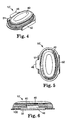
- the second section 40 is effective for covering the opening 39 in the first section 30 when the second section 40 overlaps the first section 30 , thereby rendering the dispenser 10' portable as shown in Figures 4-6.
- a convenient means for releasably securing the second section 40 to the first section 30 with the first major surface 41 of the second section 40 facing the second major surface 32 of the first section 30 is shown in Figures 1 and 3.
- a peripheral bump 37 extends outward from the second major surface 32 of the first section 30 .
- a corresponding peripheral flange 45 projects inward from the first major surface 41 of the second section 40 .
- the second section 40 is releasably secured to the first section 30 when the first section 30 is secured to the central section 20 and the peripheral flange 45 on the second section 40 is forced past the peripheral bump 37 on the first section 30 . This can be accomplished by simply overlapping the sections, with the first major surface 41 of the second section 40 facing the second major surface 32 of the first section 30 , and squeezing the sections together until they "snap" into place.
- a tab 46 is preferrably provided opposite the second living hinge 52 for facilitating opening of the dispenser 10' .
- Table One provides a summary of acceptable and preferred dimensions for the various elements of one embodiment of the dispenser blank 10 effective for accommodating and dispensing commonly available tape strip pads 100 .
- the dispenser blank 10 may be constructed from a number of different suitable materials including specifically, but not exclusively card stock and thermoplastic sheet materials such as polyethylene, polypropylene and polyethylene terephthalate.
- the dispenser blank 10 may be quickly and inexpensively thermoformed from a sheet of recyclable thermoplastic material having a generally uniform thickness of between about 10 to 30 mils.
- the dispenser blank 10 may be quickly assembled into a portable dispenser 10' by sequentially (i) adhering or otherwise attaching a tape strip pad 100 to the first major surface 21 of the central section 20 as shown in Figure 2, (ii) pivoting the first section 30 about the first living hinge 51 into overlapping engagement with the central section 20 with first major surface 31 of the first section 30 facing the first major surface 21 of the central section 20 , (iii) snapping the first section 30 and central section 20 together, (iv) pivoting the second section 40 about the second living hinge 52 into overlapping engagement with the first section 30 with the first major surface 41 of the second section 40 facing the second major surface 32 of the first section 30 , and (v) snapping the first section 30 and second section 40 together.
- a tape strip may be dispensed from the dispenser 10' by sequentially (i) gripping the tab 46 while holding onto the edges of the central 20 and/or first 30 sections and detaching the second section 40 from the first section 30 , (ii) pivoting the second section 40 about the second living hinge 52 away from the first section 30 so as to expose the opening 39 in the first section 30 , (iii) pulling on the free end of the uppermost tape strip extending through the opening 39 until the uppermost tape strip is completely detached from the underlying tape strip, (iv) permitting the free end of the underlying tape strip (now the uppermost tape strip) extending through the opening 39 to fall back into contact with a projection 36 , (v) repeating steps (iii) and (iv) as necessary to dispense the desired number of individual tape strips, (vi) pivoting the second section 40 about the second living hinge 52 back into overlapping engagement with the first section 30 with the first major surface 41 of the second section 40 facing the second major surface 32 of the first section 30 , and (vii) snapping
Description
- x
- Longitudinal Axis of Dispenser Blank
- y
- Latitudinal Axis of Dispenser Blank
- 10'
- Assembled Dispenser
- 11
- First Major Surface
- 12
- Second Major Surface
- 20
- Central Section of Blank
- 21
- First Major Surface of Central Section
- 22
- Second Major Surface of Central Section
- 23
- First Side of Central Section
- 24
- Second Side of Central Section
- 25
- Circumferential Wall
- 26
- Outer Surface of Circumferential Wall
- 27
- Circumferential Bump Projecting Outward from Outer Surface of Circumferential Wall
- 29
- Open Well
- 30
- First Section
- 31
- First Major Surface of First Section
- 32
- Second Major Surface of First Section
- 33
- First Side of First Section
- 34
- Second Side of First Section
- 35
- Circumferential Flange Projecting Inward from First Major Surface of First Section
- 36
- Projections
- 37
- Peripheral Bump Projecting Outward from Second Major Surface of First Section
- 39
- Access Opening
- 39a
- First Longitudinal End of Opening
- 39b
- Second Longitudinal End of Opening
- 40
- Second Section
- 41
- First Major Surface of Second Section
- 42
- Second Major Surface of Second Section
- 43
- First Side of Second Section
- 44
- Second Side of Second Section
- 45
- Peripheral Flange Projecting Inward from First Major Surface of Second Section
- 46
- Tab
- 51
- Living Hinge Connecting First Section to Central Section
- 52
- Living Hinge Connecting Second Section to Central Section
- 60
- Retention Chamber
- 100
- Tape Strip Pad


Claims (9)
- A single-piece dispenser blank (10) of integrally formed construction having opposed first (11) and second (12) surfaces, comprising:(a) a central section (20) having a circumferential wall (25) projecting from the first surface and defining an open well,(b) a first section (30) pivotably connected to the central section and having a first surface (31) defining a cavity, a second surface (32), an access opening (39) and projections (36) extending from the second surface proximate opposite ends of the opening,(c) a means (27, 35) for repeatedly permitting nondestructive attachment and detachment of the first section (30) to the central section (20), with the first surface of the first section in overlapping engagement with the first surface of the central section,(d) a second section (40) pivotably connected to the central section (20) and having a first surface (41) defining a cavity, and(e) a means (37, 45) for repeatedly permitting nondestructive attachment and detachment of the second section (40) to the first section, with the first surface of the second section in overlapping engagement with the second surface of the first section,(f) wherein the sections (20, 30, 40) are configured and arranged relative to one another such that (i) the first surface (21) of the central section (20) and the first surface (31) of the first section (30) cooperatively form a retention chamber when the first surface of the first section is pivoted into overlapping engagement with the first surface of the central section, and (ii) the second section (40) covers the opening in the first section (30) when (A) the first surface (31) of the first section (30) is pivoted into overlapping engagement with the first surface (21) of the central section (20), and (B) the first surface (41) of the second section (40) is pivoted into overlapping engagement with the second surface (32) of the first section (30).
- The dispenser blank of claim 1, further comprising a tape strip pad (100) attached to the first surface of the central section within the open well.
- The dispenser blank of claim 2, wherein the tape strip pad (100) is adhesively attached to the first surface of the central section within the open well.
- The dispenser blank of any of claims 1 to 3, further comprising a tab (46) extending from a side of the second section in diametric opposition to that portion of the second section pivotably attached to the central section.
- The dispenser blank of any of claims 1 to 4, wherein the dispenser blank (10) is constructed from a single sheet of thermoplastic sheet material.
- The dispenser blank of any of claims 1 to 5, wherein:(a) the central section has a longitudinal length of between about 7 to 10 cm and a lateral width of about 3 to 5 cm,(b) the open well has a depth of about 0.2 to 2 cm,(c) the first section has a longitudinal length of between about 7 to 10 cm, a lateral width of about 3 to 5 cm, and a depth of about 0.5 to 2 cm,(d) the opening has a longitudinal length of about 2 to 5 cm and a lateral width of about 1 to 3 cm,(e) the projections have a depth of about 0.2 to 0.5 cm,(f) the second section has a longitudinal length of between about 7 to 10 cm, a lateral width of about 3 to 5 cm, and a depth of about 0.5 to 2 cm, and(g) the retention chamber has a longitudinal length of between about 5 to 10 cm, a lateral width of about 2 to 5 cm and a depth of about 1 to 2 cm.
- The dispenser blank of any of claims 1 to 6, wherein (i) the central section has a first longitudinal end, a second longitudinal end, a first lateral side and a second lateral side, (ii) the first section is pivotably attached to the first lateral side of the central section, and (iii) the second section is pivotably attached to the second lateral side of the central section.
- The dispenser blank of any of claims 1 to 7, wherein the projections are longitudinally aligned.
- The dispenser blank of any of claims 1 to 8, wherein the second section is configured and arranged to cover substantially the entire second surface area of the first section.
Applications Claiming Priority (3)
| Application Number | Priority Date | Filing Date | Title |
|---|---|---|---|
| US126014 | 1998-07-29 | ||
| US09/126,014 US6102247A (en) | 1998-07-29 | 1998-07-29 | Trifold dispenser blank for tape strip pads |
| PCT/US1999/000226 WO2000006465A1 (en) | 1998-07-29 | 1999-01-06 | Trifold dispenser blank for tape strip pads |
Publications (2)
| Publication Number | Publication Date |
|---|---|
| EP1100731A1 EP1100731A1 (en) | 2001-05-23 |
| EP1100731B1 true EP1100731B1 (en) | 2003-11-12 |
Family
ID=22422545
Family Applications (1)
| Application Number | Title | Priority Date | Filing Date |
|---|---|---|---|
| EP99902999A Expired - Lifetime EP1100731B1 (en) | 1998-07-29 | 1999-01-06 | Trifold dispenser blank for tape strip pads |
Country Status (7)
| Country | Link |
|---|---|
| US (1) | US6102247A (en) |
| EP (1) | EP1100731B1 (en) |
| JP (1) | JP2002521284A (en) |
| KR (1) | KR100546543B1 (en) |
| AU (1) | AU2312199A (en) |
| DE (1) | DE69912796T2 (en) |
| WO (1) | WO2000006465A1 (en) |
Families Citing this family (18)
| Publication number | Priority date | Publication date | Assignee | Title |
|---|---|---|---|---|
| US6412634B1 (en) | 2000-05-01 | 2002-07-02 | Unilever Home & Personal Care Usa, Division Of Conopco, Inc. | Refillable towelette dispensing article |
| AU2002325029A1 (en) * | 2001-09-17 | 2003-04-01 | Collins And Aikman Automotive Company Inc. | Vehicle side storage box |
| US20030154931A1 (en) * | 2002-02-19 | 2003-08-21 | Morris Ostrowiecki | Vinyl bag package and storage device therefor |
| US6648173B2 (en) | 2002-03-22 | 2003-11-18 | 3M Innovative Properties Company | Dispenser for tape strip pads |
| EP1638438A1 (en) * | 2003-06-23 | 2006-03-29 | 3M Innovative Properties Company | Sheet dispenser |
| US20050184080A1 (en) * | 2004-01-30 | 2005-08-25 | Moody Brett R. | Mountable note dispenser |
| US7073684B2 (en) * | 2004-03-26 | 2006-07-11 | Kimberly-Clark Wordwide, Inc. | Dispenser for housing a plurality of folded wet wipes |
| US7232040B2 (en) * | 2004-03-26 | 2007-06-19 | Kimberly-Clark Worldwide, Inc. | Dispenser capable of dispensing sheet-like articles |
| US7275658B2 (en) * | 2004-03-26 | 2007-10-02 | Kimberly-Clark Worldwide, Inc. | Dispenser capable of dispensing sheet-like articles |
| US20070235466A1 (en) * | 2006-04-07 | 2007-10-11 | Fulscher Ryan L | Portable dispenser |
| US8033421B2 (en) * | 2007-10-03 | 2011-10-11 | Kimberly-Clark Worldwide, Inc. | Refillable travel dispenser for wet wipes |
| US20100032444A1 (en) * | 2008-08-07 | 2010-02-11 | Wanda Sheffield | Dispenser For An Orally Dissolvable Strip |
| ES2570181T3 (en) * | 2012-07-04 | 2016-05-17 | Cmc Consumer Medical Care Gmbh | Set of a plurality of wet packs in a container container for dispensing to the final consumer |
| US8915358B2 (en) | 2013-03-29 | 2014-12-23 | Kimberly-Clark Worldwide, Inc. | Wet wipes dispenser with lid positioning feature |
| US9625300B2 (en) | 2014-06-23 | 2017-04-18 | Sonoco Development, Inc. | Metering material dispenser |
| US20170150852A1 (en) * | 2015-12-01 | 2017-06-01 | Em Corporation | Water tissue |
| US10766671B2 (en) | 2017-05-23 | 2020-09-08 | Nice-Pak Products, Inc. | Lid assembly for container |
| JP7447729B2 (en) | 2020-08-05 | 2024-03-12 | Toppanホールディングス株式会社 | Shaking container |
Family Cites Families (37)
| Publication number | Priority date | Publication date | Assignee | Title |
|---|---|---|---|---|
| DE2123469A1 (en) * | 1971-05-12 | 1972-11-23 | Schröter & Bake, Werk für moderne Verpackung, 8402 Neutraubling | Dust-tight hinged lid container |
| ZA735886B (en) * | 1972-09-08 | 1974-08-28 | Reckitt & Colmann Prod Ltd | A container end or top piece for a container |
| FR2365998A1 (en) * | 1976-09-29 | 1978-04-28 | Thermo Formage Mediterraneen S | Storage and distribution container for sheets esp. toilet paper - consists of single piece moulded in three folding parts with slotted lid |
| US4781306A (en) * | 1981-02-19 | 1988-11-01 | Minnesota Mining And Manufacturing Company | Stack of sheet material |
| US4416392A (en) * | 1981-02-19 | 1983-11-22 | Minnesota Mining & Manufacturing Company | Dispenser for adhesive coated sheet material |
| US4586629A (en) * | 1984-04-02 | 1986-05-06 | Minnesota Mining And Manufacturing Company | Notepaper dispenser package |
| US4586631A (en) * | 1984-04-02 | 1986-05-06 | Minnesota Mining And Manufacturing Company | Dispensing package for sheets |
| US4562938A (en) * | 1984-04-02 | 1986-01-07 | Minnesota Mining And Manufacturing Company | Sheet dispenser |
| US4653666A (en) * | 1985-06-21 | 1987-03-31 | Minnesota Mining And Manufacturing Company | Package and dispenser for adhesive coated notepaper |
| US4742913A (en) * | 1986-05-12 | 1988-05-10 | Minnesota Mining And Manufacturing Company | Dispenser for predetermined lengths of tape |
| US4650706A (en) * | 1986-05-12 | 1987-03-17 | Minnesota Mining And Manufacturing Company | Tabbed tape pad |
| US4986440A (en) * | 1987-03-23 | 1991-01-22 | Minnesota Mining And Manufacturing Company | Dispenser for a stack of note paper |
| US5080255A (en) * | 1987-03-23 | 1992-01-14 | Minnesota Mining And Manufacturing Company | Dispenser for a stack of note paper |
| US4770320A (en) * | 1987-06-03 | 1988-09-13 | Minnesota Mining And Manufacturing Company | Sheet and dispenser package therefor |
| US4907825A (en) * | 1987-06-03 | 1990-03-13 | Minnesota Mining And Manufacturing Company | Sheet and dispenser package therefor |
| USD306462S (en) | 1988-02-24 | 1990-03-06 | Minnesota Mining And Manufacturing Company | Sheet dispenser |
| US4928864A (en) | 1988-08-22 | 1990-05-29 | Jerry Walker | Hand clasp tape dispenser |
| US4895746A (en) | 1989-03-01 | 1990-01-23 | Minnesota Mining And Manufacturing Company | Stack of pressure sensitive adhesive coated sheets |
| US4993590A (en) * | 1989-05-26 | 1991-02-19 | Minnesota Mining And Manufacturing Company | Sheet dispenser |
| US5050909A (en) * | 1990-06-01 | 1991-09-24 | Minnesota Mining And Manufacturing Company | Stack of sheet assemblies |
| US5086946A (en) * | 1990-12-10 | 1992-02-11 | Minnesota Mining And Manufacturing Company | Sheet stack and dispenser package therefor |
| US5158205A (en) * | 1991-01-11 | 1992-10-27 | Minnesota Mining And Manufacturing Company | Dispenser for a small stack of note paper |
| US5167346A (en) * | 1992-03-20 | 1992-12-01 | Minnesota Mining And Manufacturing Company | Dispenser for a stack of sheets |
| USD348690S (en) | 1992-07-30 | 1994-07-12 | Minnesota Mining And Manufacturing | Tape dispenser |
| USD348484S (en) | 1992-07-30 | 1994-07-05 | Minnesota Mining And Manufacturing | Tape dispenser |
| US5358141A (en) * | 1993-05-18 | 1994-10-25 | Minnesota Mining And Manufacturing Company | Support or attachment means for a sheet dispenser |
| US5299712A (en) * | 1993-05-18 | 1994-04-05 | Minnesota Mining And Manufacturing Company | Sheet dispenser with optional support or attachment means |
| USD359513S (en) | 1993-05-18 | 1995-06-20 | Minnesota Mining And Manufacturing Company | Sheet dispenser |
| US5411168A (en) * | 1993-08-03 | 1995-05-02 | Minnesota Mining And Manufacturing Company | Sheet dispenser and dispenser subassemblies |
| US5397117A (en) * | 1993-10-05 | 1995-03-14 | Minnesota Mining And Manufacturing Company | Sheet dispenser |
| US5769270A (en) * | 1993-11-25 | 1998-06-23 | Minnesota Mining And Manufacturing Company | Tape or sheet dispenser |
| US5518144A (en) * | 1994-06-21 | 1996-05-21 | Minnesota Mining And Manufacturing Company | Dispenser package |
| US5526955A (en) * | 1994-09-14 | 1996-06-18 | Minnesota Mining And Manufacturing Company | Assembly including refillable compact sheet dispenser |
| US5671866A (en) * | 1995-12-27 | 1997-09-30 | Minnesota Mining And Manufacturing Company | Refillable sheet dispenser with storage |
| US5755356A (en) * | 1996-04-15 | 1998-05-26 | Minnesota Mining And Manufacturing Company | Compressible sheet dispenser |
| US5794815A (en) * | 1996-06-19 | 1998-08-18 | Minnesota Mining And Manufacturing Company | Dispensers with optional support or attachment means |
| USD387806S (en) | 1996-06-19 | 1997-12-16 | Minnesota Mining And Manufacturing Company | Sheet dispenser |
-
1998
- 1998-07-29 US US09/126,014 patent/US6102247A/en not_active Expired - Fee Related
-
1999
- 1999-01-06 AU AU23121/99A patent/AU2312199A/en not_active Abandoned
- 1999-01-06 KR KR1020017001135A patent/KR100546543B1/en not_active IP Right Cessation
- 1999-01-06 WO PCT/US1999/000226 patent/WO2000006465A1/en active IP Right Grant
- 1999-01-06 DE DE69912796T patent/DE69912796T2/en not_active Expired - Fee Related
- 1999-01-06 JP JP2000562278A patent/JP2002521284A/en active Pending
- 1999-01-06 EP EP99902999A patent/EP1100731B1/en not_active Expired - Lifetime
Also Published As
| Publication number | Publication date |
|---|---|
| US6102247A (en) | 2000-08-15 |
| KR100546543B1 (en) | 2006-01-26 |
| AU2312199A (en) | 2000-02-21 |
| WO2000006465A1 (en) | 2000-02-10 |
| KR20010074774A (en) | 2001-08-09 |
| DE69912796D1 (en) | 2003-12-18 |
| DE69912796T2 (en) | 2004-09-23 |
| JP2002521284A (en) | 2002-07-16 |
| EP1100731A1 (en) | 2001-05-23 |
Similar Documents
| Publication | Publication Date | Title |
|---|---|---|
| EP1100731B1 (en) | Trifold dispenser blank for tape strip pads | |
| AU672546B2 (en) | Sheet stack and dispenser package therefor | |
| US7185785B2 (en) | Tape sheet pads and dispenser and method of dispensing individual tape sheets from such pads | |
| US6439386B1 (en) | Packaged absorbent paper product, container, and dispensing method | |
| EP0837827B1 (en) | Hanger sheet and tape dispenser combination | |
| US6644498B1 (en) | Continuous roll paper napkin rings | |
| EP0646477B1 (en) | Sheet dispenser | |
| AU718058B2 (en) | Adhesive tape strip and tape flag pads with center tabbed leader strip | |
| AU623671B2 (en) | Concatenation of circular abrasive discs | |
| US6648173B2 (en) | Dispenser for tape strip pads | |
| AU689909B2 (en) | Dispenser package for use in ring binders | |
| WO2003072443A1 (en) | Package with adhesive hanging means | |
| TW461918B (en) | Set of stacks of adhesive coated sheets and dispenser for dispensing sheets from a stack of sheets | |
| US20210122945A1 (en) | Tape strip stack | |
| JPH11503700A (en) | Dispenser package | |
| MXPA01004739A (en) | Heavy duty pre-cut adhesive coated tapes and dispenser |
Legal Events
| Date | Code | Title | Description |
|---|---|---|---|
| PUAI | Public reference made under article 153(3) epc to a published international application that has entered the european phase |
Free format text: ORIGINAL CODE: 0009012 |
|
| 17P | Request for examination filed |
Effective date: 20010221 |
|
| AK | Designated contracting states |
Kind code of ref document: A1 Designated state(s): DE FR GB IT |
|
| 17Q | First examination report despatched |
Effective date: 20020703 |
|
| GRAH | Despatch of communication of intention to grant a patent |
Free format text: ORIGINAL CODE: EPIDOS IGRA |
|
| GRAS | Grant fee paid |
Free format text: ORIGINAL CODE: EPIDOSNIGR3 |
|
| GRAA | (expected) grant |
Free format text: ORIGINAL CODE: 0009210 |
|
| AK | Designated contracting states |
Kind code of ref document: B1 Designated state(s): DE FR GB IT |
|
| REG | Reference to a national code |
Ref country code: GB Ref legal event code: FG4D |
|
| REF | Corresponds to: |
Ref document number: 69912796 Country of ref document: DE Date of ref document: 20031218 Kind code of ref document: P |
|
| ET | Fr: translation filed | ||
| PLBE | No opposition filed within time limit |
Free format text: ORIGINAL CODE: 0009261 |
|
| STAA | Information on the status of an ep patent application or granted ep patent |
Free format text: STATUS: NO OPPOSITION FILED WITHIN TIME LIMIT |
|
| 26N | No opposition filed |
Effective date: 20040813 |
|
| PGFP | Annual fee paid to national office [announced via postgrant information from national office to epo] |
Ref country code: IT Payment date: 20080128 Year of fee payment: 10 Ref country code: GB Payment date: 20080129 Year of fee payment: 10 |
|
| PGFP | Annual fee paid to national office [announced via postgrant information from national office to epo] |
Ref country code: FR Payment date: 20080117 Year of fee payment: 10 Ref country code: DE Payment date: 20080229 Year of fee payment: 10 |
|
| REG | Reference to a national code |
Ref country code: HK Ref legal event code: WD Ref document number: 1038221 Country of ref document: HK |
|
| GBPC | Gb: european patent ceased through non-payment of renewal fee |
Effective date: 20090106 |
|
| PG25 | Lapsed in a contracting state [announced via postgrant information from national office to epo] |
Ref country code: DE Free format text: LAPSE BECAUSE OF NON-PAYMENT OF DUE FEES Effective date: 20090801 |
|
| REG | Reference to a national code |
Ref country code: FR Ref legal event code: ST Effective date: 20091030 |
|
| PG25 | Lapsed in a contracting state [announced via postgrant information from national office to epo] |
Ref country code: GB Free format text: LAPSE BECAUSE OF NON-PAYMENT OF DUE FEES Effective date: 20090106 |
|
| PG25 | Lapsed in a contracting state [announced via postgrant information from national office to epo] |
Ref country code: FR Free format text: LAPSE BECAUSE OF NON-PAYMENT OF DUE FEES Effective date: 20090202 |
|
| PG25 | Lapsed in a contracting state [announced via postgrant information from national office to epo] |
Ref country code: IT Free format text: LAPSE BECAUSE OF NON-PAYMENT OF DUE FEES Effective date: 20090106 |