EP1100648B1 - An apparatus for securing components upon a structural member - Google Patents
An apparatus for securing components upon a structural member Download PDFInfo
- Publication number
- EP1100648B1 EP1100648B1 EP99934888A EP99934888A EP1100648B1 EP 1100648 B1 EP1100648 B1 EP 1100648B1 EP 99934888 A EP99934888 A EP 99934888A EP 99934888 A EP99934888 A EP 99934888A EP 1100648 B1 EP1100648 B1 EP 1100648B1
- Authority
- EP
- European Patent Office
- Prior art keywords
- bladder
- pipe arrangement
- structural member
- fluid pressure
- order
- Prior art date
- Legal status (The legal status is an assumption and is not a legal conclusion. Google has not performed a legal analysis and makes no representation as to the accuracy of the status listed.)
- Expired - Lifetime
Links
- 239000012530 fluid Substances 0.000 claims description 33
- 239000000463 material Substances 0.000 claims description 12
- 239000003550 marker Substances 0.000 claims description 5
- 239000004033 plastic Substances 0.000 claims description 5
- 229920003023 plastic Polymers 0.000 claims description 5
- 229920002635 polyurethane Polymers 0.000 claims description 2
- 239000004814 polyurethane Substances 0.000 claims description 2
- 238000001125 extrusion Methods 0.000 description 6
- 238000004519 manufacturing process Methods 0.000 description 5
- 238000000034 method Methods 0.000 description 5
- 229910000838 Al alloy Inorganic materials 0.000 description 4
- 235000013290 Sagittaria latifolia Nutrition 0.000 description 4
- XAGFODPZIPBFFR-UHFFFAOYSA-N aluminium Chemical compound [Al] XAGFODPZIPBFFR-UHFFFAOYSA-N 0.000 description 4
- 229910052782 aluminium Inorganic materials 0.000 description 4
- 239000004411 aluminium Substances 0.000 description 4
- 235000015246 common arrowhead Nutrition 0.000 description 4
- 230000008878 coupling Effects 0.000 description 4
- 238000010168 coupling process Methods 0.000 description 4
- 238000005859 coupling reaction Methods 0.000 description 4
- 238000005336 cracking Methods 0.000 description 3
- 235000012489 doughnuts Nutrition 0.000 description 3
- 239000002244 precipitate Substances 0.000 description 3
- 230000009467 reduction Effects 0.000 description 3
- 230000008901 benefit Effects 0.000 description 2
- 230000005540 biological transmission Effects 0.000 description 2
- 230000009172 bursting Effects 0.000 description 2
- 230000004044 response Effects 0.000 description 2
- OKTJSMMVPCPJKN-UHFFFAOYSA-N Carbon Chemical compound [C] OKTJSMMVPCPJKN-UHFFFAOYSA-N 0.000 description 1
- CWYNVVGOOAEACU-UHFFFAOYSA-N Fe2+ Chemical compound [Fe+2] CWYNVVGOOAEACU-UHFFFAOYSA-N 0.000 description 1
- 229910000861 Mg alloy Inorganic materials 0.000 description 1
- 229910000831 Steel Inorganic materials 0.000 description 1
- 230000006978 adaptation Effects 0.000 description 1
- 239000000853 adhesive Substances 0.000 description 1
- 238000004026 adhesive bonding Methods 0.000 description 1
- 230000001070 adhesive effect Effects 0.000 description 1
- 230000002411 adverse Effects 0.000 description 1
- 230000004888 barrier function Effects 0.000 description 1
- 229910052799 carbon Inorganic materials 0.000 description 1
- 239000000919 ceramic Substances 0.000 description 1
- 230000006835 compression Effects 0.000 description 1
- 238000007906 compression Methods 0.000 description 1
- 230000007547 defect Effects 0.000 description 1
- 238000004512 die casting Methods 0.000 description 1
- 230000000694 effects Effects 0.000 description 1
- 230000005288 electromagnetic effect Effects 0.000 description 1
- 239000000835 fiber Substances 0.000 description 1
- 230000001939 inductive effect Effects 0.000 description 1
- 239000007788 liquid Substances 0.000 description 1
- 238000003754 machining Methods 0.000 description 1
- 238000005259 measurement Methods 0.000 description 1
- 230000007246 mechanism Effects 0.000 description 1
- 238000000465 moulding Methods 0.000 description 1
- 239000003973 paint Substances 0.000 description 1
- 239000006223 plastic coating Substances 0.000 description 1
- 230000008569 process Effects 0.000 description 1
- 239000011208 reinforced composite material Substances 0.000 description 1
- 239000002990 reinforced plastic Substances 0.000 description 1
- 239000010959 steel Substances 0.000 description 1
- 230000003319 supportive effect Effects 0.000 description 1
- 239000000725 suspension Substances 0.000 description 1
- 238000003466 welding Methods 0.000 description 1
Images


Classifications
-
- B—PERFORMING OPERATIONS; TRANSPORTING
- B62—LAND VEHICLES FOR TRAVELLING OTHERWISE THAN ON RAILS
- B62D—MOTOR VEHICLES; TRAILERS
- B62D27/00—Connections between superstructure or understructure sub-units
- B62D27/02—Connections between superstructure or understructure sub-units rigid
- B62D27/023—Assembly of structural joints
-
- B—PERFORMING OPERATIONS; TRANSPORTING
- B21—MECHANICAL METAL-WORKING WITHOUT ESSENTIALLY REMOVING MATERIAL; PUNCHING METAL
- B21D—WORKING OR PROCESSING OF SHEET METAL OR METAL TUBES, RODS OR PROFILES WITHOUT ESSENTIALLY REMOVING MATERIAL; PUNCHING METAL
- B21D39/00—Application of procedures in order to connect objects or parts, e.g. coating with sheet metal otherwise than by plating; Tube expanders
- B21D39/04—Application of procedures in order to connect objects or parts, e.g. coating with sheet metal otherwise than by plating; Tube expanders of tubes with tubes; of tubes with rods
-
- B—PERFORMING OPERATIONS; TRANSPORTING
- B23—MACHINE TOOLS; METAL-WORKING NOT OTHERWISE PROVIDED FOR
- B23P—METAL-WORKING NOT OTHERWISE PROVIDED FOR; COMBINED OPERATIONS; UNIVERSAL MACHINE TOOLS
- B23P11/00—Connecting or disconnecting metal parts or objects by metal-working techniques not otherwise provided for
- B23P11/005—Connecting or disconnecting metal parts or objects by metal-working techniques not otherwise provided for by expanding or crimping
-
- B—PERFORMING OPERATIONS; TRANSPORTING
- B62—LAND VEHICLES FOR TRAVELLING OTHERWISE THAN ON RAILS
- B62D—MOTOR VEHICLES; TRAILERS
- B62D25/00—Superstructure or monocoque structure sub-units; Parts or details thereof not otherwise provided for
- B62D25/08—Front or rear portions
- B62D25/14—Dashboards as superstructure sub-units
- B62D25/145—Dashboards as superstructure sub-units having a crossbeam incorporated therein
Definitions
- This invention relates to an apparatus for securing components upon a structural member and in particular to a beam for use in a motor vehicle.
- transverse beam for a motor vehicle extending from one side of the motor vehicle to the other side of the motor vehicle behind a dashboard of the motor vehicle in order to support an airbag housing for a passenger of the motor vehicle.
- the transverse beam acting as a structural member able to withstand the forces imposed upon it by an airbag fitted within the airbag housing.
- US 5,752,311 discloses an apparatus with a bladder to expand tubular members.
- the bladder is flexible about its longitudinal axis, with a mandrel inside including a plurality of segments interconnected by ball-and-socket joints.
- an apparatus for securing components upon a hollow structural member comprising a pipe arrangement and a bladder, said pipe arrangement being configured to deliver fluid pressure to said bladder and said bladder being adjustable upon said pipe arrangement to allow entry in use, to a hollow structural member with that member associated with a component thereabout, said bladder being thus arranged to allow location adjacent to said member an d to expand under said fluid pressure to locally deform the hollow structural member into interference fastening with the component, wherein the pipe arrangement comprises a plurality of pipe sections with a bladder In between, wherein at least one of the pipe sections is made up of a flexible tubing in order to facilitate entry of the apparatus into the hollow structural member and the flexible tubing being not or only marginally inflatable.
- the pipe arrangement could include an aperture to allow transfer of fluid pressure to the bladder.
- Each bladder could be made from a bubble of plastics material. Furthermore, in order to maximise radial expansion, lateral expansion of the bladder could be inhibited with retainer discs at either end of the bladder.
- the bladder could normally constrict the tube whilst the tube under fluid pressure is expanded to remove that constriction in order to expand the bladder and so deform the hollow structural member.
- the bladder could include a spigot member in order to penetratively engage the pipe arrangement to facilitate fluid coupling to the bladder and so expansion under fluid pressure.
- the bladder may include a magnetic marker in order to determine its location within the hollow structural member.
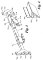
- Figures 1 to 5 illustrate two examples of a structural member and the manner by which components are secured to that member.
- a structural member 10 comprising of an elongate tubular member 9 upon which is engaged a pair of fixing brackets 11, 12, a steering column support bracket 13 and an airbag housing 14.
- these brackets 11, 12, 13 and housing 14 are collectively and singularly known as components.
- the structural member 10 forming a transverse beam assembly for mounting behind a dashboard of a motor vehicle.
- the elongate tubular member 9 is made from thin wall steel tube and has a first fixing bracket 11 secured to one end and a second fixing bracket 12 secured to the opposite end.
- the fixing brackets 11, 12 have apertures 15A, 15B; 16A, 16B formed therein through which bolts may be passed to connect the structural member 10 to part of the structure of the motor vehicle to which the structural member 10 is fitted.
- the fixing brackets 11, 12 are made from an aluminium alloy by an extrusion process such that a long length of extruded aluminium is produced having the correct outer and inner profile to form the fixing brackets. The length of extruded material is then cut into lengths equal to the width of each of the fixing brackets 11, 12. This provides a very cheap and cost effective way of manufacturing the fixing brackets 11, 12.
- the steering column support bracket is made by extrusion from an aluminium alloy and has a number of threaded apertures 17A, 17B, 17C and 17D which are used to attach the steering column of the motor vehicle to which the structural member 10 is fitted.
- the airbag housing 14 is made from an aluminium alloy by extrusion and has a C-shaped cavity 19 therein into which an airbag assembly can be fitted.
- a tubular member 9 is selected having a predetermined length, width, height and wall thickness to provide the desired strength and deflection properties for the structural beam being produced.
- the components to be secured to the tubular member 9 are then located thereon each of the components having an internal aperture 18 corresponding in size and shape to that of the tubular member 9 such that they can fit thereupon with a small clearance.
- the fixing brackets 11, 12, the steering column support bracket 13 and the airbag support housing 14 are then, along with the tubular member 9, placed in a positioning jig to ensure the correct spacing and orientation is achieved.
- tubular member 9 it is caused to plastically deform causing expansion which results in the tubular member 9 becoming an interference fit with the components 11, 12, 13 and 14 fitted thereupon.
- the tubular member 9 will be caused to bulge slightly on either side of each of the components causing them to be both axially and longitudinally secured to the tubular member 9.
- the pressure within the tubular member 9 is then released but because of the plastic deformation that has been caused the tubular member 9 remains in an interference fit condition with respect to the components 11, 12, 13, 14 such that the components are subjected to a slight tension by the inter-engagement and the tubular member 9 is subject to a small compression loading due to the inter-engagement.
- Such deformation by pressurisation is often referred to as hydroforming.
- a structural member 110 which is in many respects the same as the structural member previously described and for which common parts are given the same reference numeral with the addition of 100.
- the structural member 110 comprises of an elongate tubular member 109 upon which is engaged a number of components 111, 114 and 120.
- the components 111, 114 and 120 are secured to the tube in the same way as that previously described that is to say the tubular member 109 is plastically deformed so as to secure the components 111, 114 and 120 to it.
- the first fixing bracket 111 is as previously described and has two fixing holes 115A and 115B used to secure the fixing bracket to part of the body structure of the motor vehicle.
- the airbag housing 114 is identical to that described with reference to Figure 1.
- the second fixing member 112 and the steering column support member 123 are different from that previously described in that they are made as a one piece assembly 120 from a single aluminium extrusion.
- the extrusion is so formed that after machining it can provide not only the steering column support 123 but also the fixing bracket 122 there being a bridging component 124 formed as an integral part thereof.
- the steering column support member 123 has a number of threaded apertures 117A, 117B, 117C and 117D used to secure a steering column to the support member 123 and two apertures 116A and 116B in the fixing bracket 122 used to secure the fixing bracket to part of the body structure of the motor vehicle.
- components made from extruded aluminium it could be used to attach components made from other non-ferrous materials or other materials such as reinforced plastic or be made by a different method.
- components could be made from magnesium alloy or from moulded a carbon fibre reinforced composite material and the tube could be made from an aluminium alloy.
- the airbag housing 14, 114 could be formed as a one piece member with one of the fixing brackets in a similar manner to that in which the steering column member 123 has been formed as a one piece member with the fixing bracket 122.
- cavities 50, 51; 150, 151 depicted in the drawings have at least one thin wall which may be burst due to the pressures presented in the member 9; 109, particularly if there are already existing material defects such as cracks, etc.
- these cavities can be removed or filled such as depicted in the drawings with regard to brackets 12 and 122.
- brackets 12 and 122 normally it will be appreciated that the whole assembly including structural member 10 or 110 will be held within an enveloping tool in order to limit pressure induced deformation and so the potential for bursting/cracking.
- the housing bracket includes a key rail 203 upon which an airbag housing 204 is fixed subsequent to securing the bracket 201 to the member 202.
- the housing 204 is normally slid along the rail 203 and locked in place by a locking pin 205 or adhesive or any other appropriate technique.
- the housing bracket 201 has a much reduced and less complex profile compared to the airbag housing 204.
- the complexity of a supportive and enveloping tool to limit interference fit deformation under pressure is reduced. In such circumstances, it will be easier and cheaper to provide an adequate tool to stop bursting or rupture of the housing bracket 201 and elongate member 202 under pressure.
- the objective of the present apparatus is to secure components upon a hollow structural member. It will be appreciated that a typical technique in order to secure components upon such a hollow member and as referred to as hydroforming, is through inflation of the whole hollow structural member. It will be appreciated that such inflation is inconvenient due to the relatively large volume of liquid to be pressurised and the inability to create localised differentials in the inflation pressure as required for specific components to be secured.
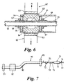
- FIG. 6 a cross-section of a portion of an apparatus in accordance with the present invention is depicted.
- a hollow structural member 61 is secured to a component 62 through an interference fit deformation 63 precipitated by a bladder 64 of the apparatus.
- This bladder 64 may be formed from a hollow polyurethane or similar material bubble.
- the bladder 64 is secured upon a pipe arrangement 65 which presents a fluid pressure internally of that bladder 64 in order to radially expand it in the direction of arrow heads R.
- a pipe arrangement 65 which presents a fluid pressure internally of that bladder 64 in order to radially expand it in the direction of arrow heads R.
- Such radial expansion in the direction of arrow heads R precipitates the deformation and therefore interference fit coupling between the structural member 61 and component 62.
- the pipe 65 is filled with a fluid and this fluid enters a cavity 66 of the bladder 64 in order to inflate that bladder 64.
- retainer discs 67 are located either side of the bladder 64 in order to inhibit lateral deformation of the bladder 64 and maximise radial expansion for fluid pressure.
- the retainer discs 67 are robustly secured to the pipe 64 through appropriate fastening elements such as a screw thread and nut 68.
- a first advantage of the present apparatus is that the volume of fluid necessary in order to create the interference fit deformation for coupling between the member 61 and the components 62 is reduced from the hollow volume of the member 61 to the volume of the pipe 65 and each bladder 64 located thereon. It will be appreciated that typically a plurality of bladders 64 will be secured upon the same pipe arrangement 65 in order to secure several components 62 to the structural member 61 in a single operation.
- the fluid pressurisation mechanism will be located at one end of the pipe arrangement 65 whilst the other end is closed.
- the inherent reduction in fluid pressure along the length of the pipe arrangement 65 i.e. due to fluid compressibility, does not adversely effect the deformation response of each bladder 64.
- adaptation of the fluid pressure presented through the bladder 64 to the member 61 may be adjusted. Such adjustment may be made through allowing varying degrees of lateral deformation by adjusting the retainer discs 67 or through provision of a regulator valve or differences in the bladder 64 constriction in terms of material thickness and time.
- each component 62 which may be secured to the structural member 61 can vary from relatively robust bracketing to more delicate or intricate elements. Excessive deformation of such delicate intricate elements could precipitate cracking which is unacceptable. For example, if a ceramic component 62 were to be secured to the member 61, it will be appreciated that the nature of the material would require careful consideration of the imposed deformation precipitated by the bladder 64.
- the pipe arrangement 65 could include sections which through appropriate pressure of valves into a reservoir section or sections would allow equalisation of pressure along the pipe arrangement 65.
- FIG 7 a schematic pictorial representation of an apparatus 71 in accordance with the present invention is depicted.
- the apparatus 71 comprises a first bladder 72 and a second bladder 73 secured together through a pipe arrangement 74.
- This pipe arrangement 74 comprises pipe sections 75, 76, 77 along with a flexible pipe section 78.
- the apparatus 71 comprises a closed fluid system such that upon presentation of a fluid pressure from an appropriate source, the bladders 72, 73 are radially expansive.
- These bladders 72, 73 operate in a similar manner to that described with regard to bladder 64 in Figure 6 above.
- the apparatus 71 enters a structural member 79 in the direction of arrow head A. Such entry and traversal of a bend 80 in the member 79 is facilitated by inclusion of the flexible section 78. Entry of the apparatus 71 into the members 79 is progressed until respective bladders 72, 73 are located about and substantially below respective components 81, 82. Such location is achieved through consideration of the distance between the bladder 72, 73 in terms of a combination of pipe sections 75, 76 and flexible section 78. A further component 83 is secured to the member 79 through an additional bladder secured to the pipe arrangement 74 but not shown.
- the bladder 72, 73 Upon application of a fluid pressure, the bladder 72, 73 expands in order to locally deform the member 79 into interference engagement with each component 81, 82 such that they are secured to that member 79.
- each bladder could be configured as a closed doughnut about a flexible pipe arrangement 65.
- This doughnut could be filled with a transmission fluid such that pressure applied through the pipe 65 is transferred to the bladder 64 through that transmission fluid.
- this doughnut configuration of the bladder 64 would naturally constrict the pipe arrangement 65 or flexible tube such that upon application of the fluid pressure, this constriction is relieved in order to expand that bladder 64.
- each bladder could include spigot means to precipitate a passage into a pipe arrangement 64. where required.
- a length of pipe 65 would be acquired and passed through a bladder to an appropriate distance equivalent to the location of the desired component upon the member 61 at which point the bladder would be compressed possibly by a percussive force such that a spigot spear member in the bladder would penetrate the pipe 65 and so provide a passage to that bladder.
- the bladder subsequently being further secured at that location upon the pipe 64 through retainer discs and fastener means described previously.
- location of the bladder in accordance with the present apparatus is important in order to ensure localised deformation of the structural member coincides with the component position.
- one manner of achieving such appropriate location for the bladder is through prior measurement of the distance of bladder spacing upon the pipe arrangement 65 from an entry point to the structural member.
- a magnetic or other marker type could be secured to the bladder.
- Such a magnetic marker may be of a permanent type or produce a magnetic field through an electromagnetic effect.
- a further benefit of such a magnetic marker may be that sufficient magnetic attraction may be achieved between the bladder and a magnetically inducible component in order to temporarily locate that component prior to more permanent securing deformation of the structural member into interference engagement with the component.
- the invention also relates to a roll-over cage assembies, struts or suspension tie bars etc.
- the beam could be sleeved in plastic to eliminate the need for separate paint finishes etc.
Landscapes
- Engineering & Computer Science (AREA)
- Mechanical Engineering (AREA)
- Chemical & Material Sciences (AREA)
- Combustion & Propulsion (AREA)
- Transportation (AREA)
- Shaping Metal By Deep-Drawing, Or The Like (AREA)
- Air Bags (AREA)
Description
Claims (8)
- An apparatus (71) for securing components upon a hollow structural member (9; 109), the apparatus (71) comprising a pipe arrangement (65; 74) and a bladder (64; 72, 73), said pipe arrangement (65; 74) being configured to deliver fluid pressure to said bladder (64; 72, 73) and said bladder (64; 72, 73) being adjustable upon said pipe arrangement (65; 74) to allow entry in use, to a hollow structural member (9; 109) with that member associated with a component thereabout, said bladder (64; 72, 73) being thus arranged to allow location adjacent to said member (9; 109) and to expand under said fluid pressure to locally deform the hollow structural member (9; 109) into interference fastening with the component,
wherein the pipe arrangement (65; 74) comprises a plurality of pipe sections with a bladder in between, characterized in that at least one of the pipe sections (78) is made up of a flexible tubing in order to facilitate entry of the apparatus (71) into the hollow structural member (9; 109) and the flexible tubing being not or only marginally inflatable. - An apparatus as claimed in claim 1,
wherein the bladder (64) is associated with retainer discs (67) and fastener means (68) in order to inhibit lateral deformation of the bladder (64) under fluid pressure. - An apparatus as claimed in Claim 1 or 2,
wherein the fluid pressure is delivered from the pipe arrangement (65) to the bladder (64) through an aperture (69) in the pipe arrangement (65) coupled to a cavity in the bladder (64). - An apparatus as claimed in any preceding claim,
wherein the bladder (64) comprises a balloon of plastics material. - An apparatus as claimed in Claim 4,
wherein the plastics material is polyurethane or similar material. - An apparatus as claimed in any preceding claim,
wherein the bladder (64) in a normal state presents a constriction to the pipe arrangement and said constriction is relieved by the fluid pressure in order to expand the bladder (64) and so deform the hollow structural member (9; 109). - An apparatus as claimed in any of Claims 1 to 5,
wherein the bladder (64) includes spigot means arranged to penetrate the pipe arrangement under percussive pressure in order to facilitate delivery of fluid pressure from that pipe arrangement to the bladder (64). - An apparatus as claimed in any preceding claim,
wherein the bladder is associated with a magnetic marker means in order to facilitate location of the bladder within a hollow structural member.
Applications Claiming Priority (3)
| Application Number | Priority Date | Filing Date | Title |
|---|---|---|---|
| GB9816570 | 1998-07-30 | ||
| GB9816570A GB2340058A (en) | 1998-07-30 | 1998-07-30 | An apparatus for securing components upon a structural member |
| PCT/GB1999/002333 WO2000006337A1 (en) | 1998-07-30 | 1999-07-20 | An apparatus for securing components upon a structural member |
Publications (2)
| Publication Number | Publication Date |
|---|---|
| EP1100648A1 EP1100648A1 (en) | 2001-05-23 |
| EP1100648B1 true EP1100648B1 (en) | 2003-09-17 |
Family
ID=10836409
Family Applications (1)
| Application Number | Title | Priority Date | Filing Date |
|---|---|---|---|
| EP99934888A Expired - Lifetime EP1100648B1 (en) | 1998-07-30 | 1999-07-20 | An apparatus for securing components upon a structural member |
Country Status (4)
| Country | Link |
|---|---|
| EP (1) | EP1100648B1 (en) |
| DE (1) | DE69911428T2 (en) |
| GB (1) | GB2340058A (en) |
| WO (1) | WO2000006337A1 (en) |
Families Citing this family (5)
| Publication number | Priority date | Publication date | Assignee | Title |
|---|---|---|---|---|
| JP4339739B2 (en) * | 2004-04-26 | 2009-10-07 | 太陽誘電株式会社 | Multi-layer board with built-in components |
| DE102006001348A1 (en) * | 2006-01-09 | 2007-07-12 | Behr Gmbh & Co. Kg | Hybrid cross beam for motor vehicle, has retainer that is attached at base part of cross beam, where retainer consists of light metal or plastic and is integrally cast on outer side at base part |
| JP7115354B2 (en) | 2019-02-15 | 2022-08-09 | トヨタ自動車株式会社 | Steering support fixing method and fixing device, deformation confirmation method of instrument panel reinforcement main body |
| JP7320431B2 (en) * | 2019-11-15 | 2023-08-03 | 株式会社神戸製鋼所 | Structural body and manufacturing method thereof |
| WO2025155733A2 (en) * | 2024-01-16 | 2025-07-24 | Capstan Medical Inc. | Cardiac implant loading and delivery systems |
Family Cites Families (11)
| Publication number | Priority date | Publication date | Assignee | Title |
|---|---|---|---|---|
| US4159564A (en) * | 1978-04-14 | 1979-07-03 | Westinghouse Electric Corp. | Mandrel for hydraulically expanding a tube into engagement with a tubesheet |
| KR850001846B1 (en) * | 1980-06-05 | 1985-12-28 | 더 뱁콕 앤드 윌콕스 캄패니 | Apparatus for controlling expansion of a tube within a tube sheet |
| US4635333A (en) * | 1980-06-05 | 1987-01-13 | The Babcock & Wilcox Company | Tube expanding method |
| US4513497A (en) * | 1980-06-05 | 1985-04-30 | The Babcock & Wilcox Company | Tube expanding system |
| DE3203144A1 (en) * | 1982-01-30 | 1983-08-11 | Wilfried 4630 Bochum Busse | Method for the pressure-tight fixing of a tube in a tube plate or the like |
| US4724693A (en) * | 1985-12-20 | 1988-02-16 | Combustion Engineering, Inc. | Tube expansion tool |
| DE3720487C1 (en) * | 1987-06-20 | 1988-10-20 | Uni Cardan Ag | Hydraulic expansion device |
| US5479699A (en) * | 1994-02-07 | 1996-01-02 | Westinghouse Electric Corporation | Apparatus for expanding tubular members |
| US5557840A (en) * | 1995-02-13 | 1996-09-24 | J. E. Miller Inc. | Tube sheet locator and tube expander |
| DE19548341C1 (en) * | 1995-12-22 | 1996-12-19 | Daimler Benz Ag | Rigid connection for overlapping motor vehicle body parts |
| DE19618626C2 (en) * | 1996-05-09 | 2001-03-08 | Daimler Chrysler Ag | Inseparable connection and an arrangement for producing the same |
-
1998
- 1998-07-30 GB GB9816570A patent/GB2340058A/en not_active Withdrawn
-
1999
- 1999-07-20 EP EP99934888A patent/EP1100648B1/en not_active Expired - Lifetime
- 1999-07-20 WO PCT/GB1999/002333 patent/WO2000006337A1/en not_active Ceased
- 1999-07-20 DE DE69911428T patent/DE69911428T2/en not_active Expired - Lifetime
Also Published As
| Publication number | Publication date |
|---|---|
| DE69911428T2 (en) | 2004-06-17 |
| GB9816570D0 (en) | 1998-09-30 |
| WO2000006337A1 (en) | 2000-02-10 |
| GB2340058A (en) | 2000-02-16 |
| DE69911428D1 (en) | 2003-10-23 |
| EP1100648A1 (en) | 2001-05-23 |
Similar Documents
| Publication | Publication Date | Title |
|---|---|---|
| US6276740B1 (en) | Method of securing components together and a structural member made by said method | |
| KR100393534B1 (en) | Cradle assembly | |
| CN100465002C (en) | Hydroformed control arms | |
| US5927120A (en) | Apparatus for performing a hydroforming operation | |
| US6585331B2 (en) | Tubular axle beam | |
| JPH0911722A (en) | Manufacture of tubular suspension system element | |
| ES2272348T3 (en) | COMPREHENSIVE HYDROCONFORMATION. | |
| US4951492A (en) | Hydraulic expansion of tubing | |
| CA2753092C (en) | Method of producing tailored tubes | |
| EP3604087B1 (en) | Vehicle structural member and method for producing same | |
| EP1304280A2 (en) | Cast aluminum vehicle subframe with tension/compression struts | |
| EP1100648A1 (en) | An apparatus for securing components upon a structural member | |
| US20140223983A1 (en) | Multi-Stage Tube Hydroforming Process | |
| US6299242B1 (en) | Vehicle frame part in the shape of a hollow profile | |
| HUE025846T2 (en) | Clamping and release mechanism for preformed pipes in a given form | |
| US4397173A (en) | Tube expander | |
| WO1998036203A9 (en) | Tubular end connection using snap ring | |
| JP6990835B2 (en) | Instrument panel hose and its manufacturing method | |
| JP2006264444A (en) | Steering support beam and manufacturing method | |
| US5504995A (en) | Process for fitting at least one metal piece which has at least one cylindrical bore around a metal tube | |
| EP4023356B1 (en) | Structure and method for producing same | |
| PL156835B1 (en) | Method for fixing elements possessing a hole bored in the body and a device for assembling elements possessing a hole bored in the body | |
| US20040146340A1 (en) | Hydroformed tubular structure | |
| EP0632874A1 (en) | Pipeline repair apparatus including expandable forms | |
| US12275457B2 (en) | Vehicle structural member and method for manufacturing same |
Legal Events
| Date | Code | Title | Description |
|---|---|---|---|
| PUAI | Public reference made under article 153(3) epc to a published international application that has entered the european phase |
Free format text: ORIGINAL CODE: 0009012 |
|
| 17P | Request for examination filed |
Effective date: 20001223 |
|
| AK | Designated contracting states |
Kind code of ref document: A1 Designated state(s): AT BE CH CY DE DK ES FI FR GB GR IE IT LI LU MC NL PT SE |
|
| 17Q | First examination report despatched |
Effective date: 20020411 |
|
| GRAH | Despatch of communication of intention to grant a patent |
Free format text: ORIGINAL CODE: EPIDOS IGRA |
|
| GRAH | Despatch of communication of intention to grant a patent |
Free format text: ORIGINAL CODE: EPIDOS IGRA |
|
| GRAA | (expected) grant |
Free format text: ORIGINAL CODE: 0009210 |
|
| AK | Designated contracting states |
Kind code of ref document: B1 Designated state(s): DE FR GB |
|
| REG | Reference to a national code |
Ref country code: GB Ref legal event code: FG4D |
|
| REF | Corresponds to: |
Ref document number: 69911428 Country of ref document: DE Date of ref document: 20031023 Kind code of ref document: P |
|
| REG | Reference to a national code |
Ref country code: IE Ref legal event code: FG4D |
|
| ET | Fr: translation filed | ||
| PLBE | No opposition filed within time limit |
Free format text: ORIGINAL CODE: 0009261 |
|
| STAA | Information on the status of an ep patent application or granted ep patent |
Free format text: STATUS: NO OPPOSITION FILED WITHIN TIME LIMIT |
|
| 26N | No opposition filed |
Effective date: 20040618 |
|
| REG | Reference to a national code |
Ref country code: IE Ref legal event code: MM4A |
|
| REG | Reference to a national code |
Ref country code: FR Ref legal event code: PLFP Year of fee payment: 18 |
|
| PGFP | Annual fee paid to national office [announced via postgrant information from national office to epo] |
Ref country code: DE Payment date: 20160726 Year of fee payment: 18 Ref country code: GB Payment date: 20160722 Year of fee payment: 18 |
|
| PGFP | Annual fee paid to national office [announced via postgrant information from national office to epo] |
Ref country code: FR Payment date: 20160722 Year of fee payment: 18 |
|
| REG | Reference to a national code |
Ref country code: DE Ref legal event code: R119 Ref document number: 69911428 Country of ref document: DE |
|
| GBPC | Gb: european patent ceased through non-payment of renewal fee |
Effective date: 20170720 |
|
| REG | Reference to a national code |
Ref country code: FR Ref legal event code: ST Effective date: 20180330 |
|
| PG25 | Lapsed in a contracting state [announced via postgrant information from national office to epo] |
Ref country code: DE Free format text: LAPSE BECAUSE OF NON-PAYMENT OF DUE FEES Effective date: 20180201 Ref country code: GB Free format text: LAPSE BECAUSE OF NON-PAYMENT OF DUE FEES Effective date: 20170720 |
|
| PG25 | Lapsed in a contracting state [announced via postgrant information from national office to epo] |
Ref country code: FR Free format text: LAPSE BECAUSE OF NON-PAYMENT OF DUE FEES Effective date: 20170731 |