EP1100284A2 - Optical router - Google Patents
Optical router Download PDFInfo
- Publication number
- EP1100284A2 EP1100284A2 EP00309084A EP00309084A EP1100284A2 EP 1100284 A2 EP1100284 A2 EP 1100284A2 EP 00309084 A EP00309084 A EP 00309084A EP 00309084 A EP00309084 A EP 00309084A EP 1100284 A2 EP1100284 A2 EP 1100284A2
- Authority
- EP
- European Patent Office
- Prior art keywords
- input
- free space
- frequency
- space region
- waveguides
- Prior art date
- Legal status (The legal status is an assumption and is not a legal conclusion. Google has not performed a legal analysis and makes no representation as to the accuracy of the status listed.)
- Withdrawn
Links
Images

Classifications
-
- H—ELECTRICITY
- H04—ELECTRIC COMMUNICATION TECHNIQUE
- H04Q—SELECTING
- H04Q11/00—Selecting arrangements for multiplex systems
- H04Q11/0001—Selecting arrangements for multiplex systems using optical switching
- H04Q11/0005—Switch and router aspects
-
- H—ELECTRICITY
- H04—ELECTRIC COMMUNICATION TECHNIQUE
- H04Q—SELECTING
- H04Q11/00—Selecting arrangements for multiplex systems
- H04Q11/0001—Selecting arrangements for multiplex systems using optical switching
- H04Q11/0005—Switch and router aspects
- H04Q2011/0007—Construction
- H04Q2011/0018—Construction using tunable transmitters or receivers
-
- H—ELECTRICITY
- H04—ELECTRIC COMMUNICATION TECHNIQUE
- H04Q—SELECTING
- H04Q11/00—Selecting arrangements for multiplex systems
- H04Q11/0001—Selecting arrangements for multiplex systems using optical switching
- H04Q11/0005—Switch and router aspects
- H04Q2011/0007—Construction
- H04Q2011/0032—Construction using static wavelength routers (e.g. arrayed waveguide grating router [AWGR] )
-
- H—ELECTRICITY
- H04—ELECTRIC COMMUNICATION TECHNIQUE
- H04Q—SELECTING
- H04Q11/00—Selecting arrangements for multiplex systems
- H04Q11/0001—Selecting arrangements for multiplex systems using optical switching
- H04Q11/0005—Switch and router aspects
- H04Q2011/0037—Operation
- H04Q2011/0045—Synchronisation
-
- H—ELECTRICITY
- H04—ELECTRIC COMMUNICATION TECHNIQUE
- H04Q—SELECTING
- H04Q11/00—Selecting arrangements for multiplex systems
- H04Q11/0001—Selecting arrangements for multiplex systems using optical switching
- H04Q11/0005—Switch and router aspects
- H04Q2011/0037—Operation
- H04Q2011/005—Arbitration and scheduling
Definitions
- the present invention relates generally to the field of telecommunications and in particular to an optical router particularly well suited for use in internetworking, e.g, Internet Protocol (IP) networks.
- IP Internet Protocol
- routers - devices which route traffic from network to network as appropriate.
- Routing is performed by determining an intended destination for packets to be routed, appropriately "coloring" the packets in a destination-specific manner, and then transmitting the colored packets through the frequency router wherein it is routed to a desired destination. Unlike prior art routing methods and apparatus, the routing is performed according to color or frequency of the packet, and not by address.
- optical multiplexing, and demultiplexing has been accomplished in the past by using an interconnection apparatus having a number of closely spaced input waveguides communicating with the input of a star coupler.
- the output of the star coupler communicates with an optical grating having a series of optical waveguides, each of these waveguides differing in length with respect to its nearest neighbor by a predetermined fixed amount.
- the grating is further connected to the input of a second star coupler, the outputs of which form the outputs of the switching, multiplexing, and demultiplexing apparatus.
- an example of such an interconnection apparatus is disclosed in United States Patent Numbers 5,002,350 and 5,136,671.
- the geometry of such an apparatus may be such that a number of separate and distinct wavelengths each launched into a separate and distinct input port of the apparatus will all combine and appear on a predetermined one of the output ports.
- the apparatus performs a multiplexing function and may advantageously also perform a demultiplexing function.
- a plurality of input wavelengths is directed to a predetermined one of the input ports of the apparatus.
- Each of the input wavelengths is separated from the others and directed to a predetermined one of the output ports of the apparatus.
- an appropriate selection of input wavelength permits switching between any selected input port to any selected output port. Accordingly, these devices are referred to as frequency routing devices.
- a plurality of output ports 30 extends from the output circle 97 of the free space region 98 and is connected to an optical grating 32.
- the optical grating 32 comprises a plurality of unequal length waveguides 34 connected to the input circle 33 of another free space region 46.
- the various input and output ports are formed from waveguides.
- these frequency routing devices may operate as multiplexers and demultiplexers of optical frequencies. For example, if a signal of amplitude A is applied to input port 2 1 , then signals of amplitudes AT 11 , AT 12 ,...AT 1N are produced at the output ports where T ik is the value of the transmission coefficient for input port 2 i and output port 4 k . Additional details concerning these frequency routing devices are found in the above-referenced patents which are incorporated herein by reference.
- router 200 comprises router body 201 having three (3) input ports 202(1), 202(2) and 202(3) and three output ports 204(1), 204(2) and 204(3).
- optical signals entering router 200 through any of the input ports 202(1)...202(3) are split into their component wavelengths which are then routed to appropriate output port(s) 204(1)...204(3) according to wavelength.
- packets such as internet protocol (IP) 405 packets include a header portion 412 which typically contains both source and destination identifiers, a data portion 414 and a check portion 410.
- IP internet protocol
- the source identifier contained within the header 412 would identify the source or origin of the packet and the destination would identify the intended destination for that packet.
- the data portion 414 of the packet contains data to be conveyed from the source to the destination and the check portion 410 is typically used by the destination to determine whether the packet 405 and the conveyed data was received correctly at that destination.
- the destination of packet 405 (which is contained within header portion 412) is "colored" according to that destination. That is, an appropriate wavelength or color of light is used to transport this packet and hence route it through the frequency router to a specific outport port.
- a tunable transmitter assembly 435 including, for example, a tunable transmitter 420, is tuned to that appropriate color and the data packet 425 is modulated by modulator 430 into a packet signal of that appropriate color.
- this colored packet signal is applied to an input port of our inventive router, it appears at a desired and specific output port of the router.
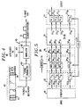
- optical internetwork router 500 comprises an NxN frequency router 501 having N input ports 508(1)...508(N) and N output ports 510(1)...510(N); transmitter array 502 including N individual tunable transmitters 502(1)...502(N); modulator array 504 including N individual modulators 504(1)...504(N); receiver array 512 including N individual receivers 512(1)...512(N); a common clock 520 and a scheduler 540.
- individual transmitters 502(1)...502(N) of the transmitter array 502 are optically connected to respective individual modulators 504(1)...504(N) of the modulator array 504 which are in turn respectively coupled to individual input ports 508(1)...508(N) of frequency router 501.
- individual output ports 510(1)...510(N) of the frequency router 501 are respectively coupled to respective individual receivers 512(1)...512(N) of receiver array 512.
- Common clock 520 provides a common clock signal to the transmitter array 502, the modulator array 504 and the receiver array 512.
- Each of the individual tunable transmitters 502(1)...502(N) of the transmitter array 502 may comprise individual tunable lasers.
- the wavelength output by each of the individual lasers is under the control of central scheduler 540 which tunes individual lasers according to destination address of data or packets of data (not shown in Fig. 5).
- individual data or data packets may be stored in buffer 550 prior to presentation to the optical internetwork router.
- the destination of the data or packet is determinative of the color on which it will be transmitted through the router. Accordingly, once the destination is determined and an appropriate color chosen, the appropriate laser is tuned to that appropriate color and the scheduler 540 controls its modulation by the appropriate modulator.
- the central scheduler may ensure that only one packet of data at a time is presented to the router and subsequently received by the receiver array 512.
- the modulators, tunable lasers and receivers since they are under control of a common clock 520, allow the synchronization of data packets at the receiver array 512.
- the lasers and the modulators are shown as distinct elements of the drawing for clarity. Clearly the lasers may be directly modulated to produce the desired effect and those skilled in the art will recognize this fact.
- frequency routers such as that used in the present invention may exhibit optical crosstalk between neighboring frequencies.
- polarization array 506 including an array of individual controllable polarizers 506(1)...506(N) may appropriately polarize the modulated optical signals prior to being input to frequency router 501.
Landscapes
- Engineering & Computer Science (AREA)
- Computer Networks & Wireless Communication (AREA)
- Optical Communication System (AREA)
- Data Exchanges In Wide-Area Networks (AREA)
- Small-Scale Networks (AREA)
- Optical Modulation, Optical Deflection, Nonlinear Optics, Optical Demodulation, Optical Logic Elements (AREA)
Abstract
Description
Claims (8)
- A routing method comprising the steps of:determining a destination for a packet to be routed;generating a carrier signal having a frequency associated with that destination; andmodulating the carrier signal with the packet to be routed.
- The method according to claim 1 further comprising the step of:applying the modulated carrier signal to a frequency routing device.
- The method according to claim 2 further comprising the steps of:decomposing, by the frequency routing device, the modulated carrier signal into spectral components; anddirecting, at least one of the spectral components to a particular destination within the frequency routing device.
- The method according to claim 3 further comprising the step of:polarizing the modulated carrier signal.
- The method according to claim 4 wherein said frequency routing device includes:at least one input waveguide;a first free space region connected to the at least one input waveguide;a plurality of output waveguides connected to the first free space region;an optical grating connected to the plurality of output waveguides comprising a plurality of unequal length waveguides;a plurality of input waveguides connected to the optical grating;a second free space region connected to the plurality of input waveguides connected to the optical grating; anda plurality of output waveguides connected to the second free space region.
- An optical router comprising:a frequency router having a plurality of input ports and a plurality of output ports;a plurality of transmitters including a plurality of tunable lasers respectively coupled to a plurality of modulators, said transmitters being respectively coupled to the plurality of input ports;a plurality of receivers respectively coupled to the plurality of output ports;a common clock providing a clock signal to the transmitters and receivers; anda scheduler coupled to the transmitter;
wherein data packets having an intended destination are modulated onto a carrier signal having a destination specific frequency and presented to an appropriate input port of the frequency routing device such that the carrier signal appears at an appropriate output port of the frequency routing device. - The router according to claim 6 further comprising:a polarization controller, coupled between the plurality of transmitters and input ports.
- The method according to claim 7 wherein said frequency routing device includes:at least one input waveguide;a first free space region connected to the at least one input waveguide;a plurality of output waveguides connected to the first free space region;an optical grating connected to the plurality of output waveguides comprising a plurality of unequal length waveguides;a plurality of input waveguides connected to the optical grating;a second free space region connected to the plurality of input waveguides connected to the optical grating; anda plurality of output waveguides connected to the second free space region.
Applications Claiming Priority (2)
| Application Number | Priority Date | Filing Date | Title |
|---|---|---|---|
| US430318 | 1982-09-30 | ||
| US09/430,318 US6594049B1 (en) | 1999-10-29 | 1999-10-29 | Optical router |
Publications (2)
| Publication Number | Publication Date |
|---|---|
| EP1100284A2 true EP1100284A2 (en) | 2001-05-16 |
| EP1100284A3 EP1100284A3 (en) | 2001-08-29 |
Family
ID=23707012
Family Applications (1)
| Application Number | Title | Priority Date | Filing Date |
|---|---|---|---|
| EP00309084A Withdrawn EP1100284A3 (en) | 1999-10-29 | 2000-10-16 | Optical router |
Country Status (3)
| Country | Link |
|---|---|
| US (1) | US6594049B1 (en) |
| EP (1) | EP1100284A3 (en) |
| JP (1) | JP3660579B2 (en) |
Cited By (2)
| Publication number | Priority date | Publication date | Assignee | Title |
|---|---|---|---|---|
| WO2003015454A3 (en) * | 2001-08-10 | 2003-05-01 | Bookham Technology Plc | Wavelength router |
| FR2832571A1 (en) * | 2001-11-22 | 2003-05-23 | Cit Alcatel | OPTICAL FIBER TRANSMISSION SYSTEM WITH COMMON CLOCK |
Families Citing this family (11)
| Publication number | Priority date | Publication date | Assignee | Title |
|---|---|---|---|---|
| US7171117B1 (en) * | 2000-08-25 | 2007-01-30 | Lucent Technologies Inc. | Optical router |
| JP3425415B2 (en) | 2000-08-31 | 2003-07-14 | 株式会社東芝 | Optical routing equipment |
| US20020124104A1 (en) * | 2001-03-01 | 2002-09-05 | Yigal Rappaport | Network element and a method for preventing a disorder of a sequence of data packets traversing the network |
| JP4160907B2 (en) * | 2002-01-30 | 2008-10-08 | エリクソン テレコムニカコエス エス.アー | Apparatus, system and method for optical packet switching using frequency header |
| JP3880994B2 (en) * | 2003-03-04 | 2007-02-14 | 富士通株式会社 | Content information distribution method, distribution system, and center station thereof |
| US6931036B2 (en) * | 2003-03-25 | 2005-08-16 | Lucent Technologies Inc. | Digitally tunable laser |
| JP5287993B2 (en) * | 2009-10-07 | 2013-09-11 | 日本電気株式会社 | Optical signal transmitter, optical signal receiver, wavelength division multiplexing optical communication device, and wavelength path system |
| US8744262B2 (en) | 2009-12-08 | 2014-06-03 | Vello Systems, Inc. | Optical subchannel routing, protection switching and security |
| JP2012060577A (en) * | 2010-09-13 | 2012-03-22 | Nippon Telegr & Teleph Corp <Ntt> | Optical matrix switch and communication method |
| US9525490B2 (en) | 2012-07-26 | 2016-12-20 | Aurrion, Inc. | Reconfigurable optical transmitter |
| US9628878B2 (en) | 2012-12-11 | 2017-04-18 | Huawei Technologies Co., Ltd. | System and method for multi-wavelength encoding |
Family Cites Families (16)
| Publication number | Priority date | Publication date | Assignee | Title |
|---|---|---|---|---|
| US5002350A (en) | 1990-02-26 | 1991-03-26 | At&T Bell Laboratories | Optical multiplexer/demultiplexer |
| US5136671A (en) | 1991-08-21 | 1992-08-04 | At&T Bell Laboratories | Optical switch, multiplexer, and demultiplexer |
| US5373517A (en) * | 1993-02-19 | 1994-12-13 | At&T Corp. | Rapidly tunable integrated laser |
| US5339157A (en) * | 1993-02-19 | 1994-08-16 | At&T Bell Laboratories | Rapidly tunable integrated optical filter |
| US5367586A (en) * | 1993-03-26 | 1994-11-22 | At&T Bell Laboratories | Optical delay line |
| DE69434263T2 (en) * | 1993-07-14 | 2006-01-12 | Nippon Telegraph And Telephone Corp. | Photonic coupling field with frequency routing for time division multiplex links |
| US5390200A (en) * | 1993-10-13 | 1995-02-14 | At&T Corp. | High power, single-frequency tunable laser |
| US5483369A (en) * | 1993-11-03 | 1996-01-09 | At&T Corp. | Communication systems using passive RF routing |
| US5600742A (en) * | 1994-09-30 | 1997-02-04 | Lucent Technologies Inc. | Wavelength grating router with output coupler |
| US5867291A (en) * | 1996-10-29 | 1999-02-02 | Chorum Technologies Inc. | Programmable wavelength router |
| US5909522A (en) * | 1997-02-07 | 1999-06-01 | Lucent Technologies Inc. | Chirped waveguide grating router with focal length adjustment |
| US6049404A (en) * | 1997-04-02 | 2000-04-11 | Macro-Vision Communications Inc. | N+M digitally programmable optical routing switch |
| US5889906A (en) * | 1997-05-28 | 1999-03-30 | Lucent Technologies Inc. | Signal router with coupling of multiple waveguide modes for provicing a shaped multi-channel radiation pattern |
| US6330236B1 (en) * | 1998-06-11 | 2001-12-11 | Synchrodyne Networks, Inc. | Packet switching method with time-based routing |
| US6243402B1 (en) * | 1999-08-31 | 2001-06-05 | Agere Systems Optoelectronics Guardian Corp. | Multi-frequency rapidly tunable laser |
| US6359912B1 (en) * | 1999-09-21 | 2002-03-19 | Lucent Technologies, Inc. | Multiple wavelength laser having a reduced number of wavelength controls |
-
1999
- 1999-10-29 US US09/430,318 patent/US6594049B1/en not_active Expired - Fee Related
-
2000
- 2000-10-16 EP EP00309084A patent/EP1100284A3/en not_active Withdrawn
- 2000-10-27 JP JP2000328182A patent/JP3660579B2/en not_active Expired - Fee Related
Cited By (2)
| Publication number | Priority date | Publication date | Assignee | Title |
|---|---|---|---|---|
| WO2003015454A3 (en) * | 2001-08-10 | 2003-05-01 | Bookham Technology Plc | Wavelength router |
| FR2832571A1 (en) * | 2001-11-22 | 2003-05-23 | Cit Alcatel | OPTICAL FIBER TRANSMISSION SYSTEM WITH COMMON CLOCK |
Also Published As
| Publication number | Publication date |
|---|---|
| EP1100284A3 (en) | 2001-08-29 |
| JP3660579B2 (en) | 2005-06-15 |
| JP2001197121A (en) | 2001-07-19 |
| US6594049B1 (en) | 2003-07-15 |
Similar Documents
| Publication | Publication Date | Title |
|---|---|---|
| JP3256419B2 (en) | Optical filter and optical signal transmission system | |
| EP3910820B1 (en) | Reconfigurable optical transmitter | |
| US6594049B1 (en) | Optical router | |
| EP0560824A1 (en) | A method and arrangement for optical switching | |
| US6072612A (en) | WDM transmitter for optical networks using a loop-back spectrally sliced light emitting device | |
| EP0543714B1 (en) | Optical fibre distribution apparatus | |
| Proietti et al. | Elastic optical networking by dynamic optical arbitrary waveform generation and measurement | |
| CN100539734C (en) | Apparatus, system and method for optical packet switching using frequency header | |
| EP1182905B1 (en) | Optical router | |
| US5121381A (en) | Optical switching apparatus for digital signal cross connection and method of interswitch optical transmission of digital signals | |
| JP3593291B2 (en) | WDM network | |
| US7260655B1 (en) | Optical routing using star switching fabric with reduced effective switching time | |
| JP2006515134A (en) | Asymmetric optical network traffic flow control | |
| US6456754B1 (en) | WDM transmitter and receiver | |
| CA1287911C (en) | Multichannel, multihop lightwave communication network | |
| JP2003244100A (en) | WDM ring network | |
| Ben Yoo et al. | Software defined elastic optical networking in temporal, spectral, and spatial domains | |
| US20090245810A1 (en) | Dynamic Signal Equalization in Optical Transmission Systems | |
| US6501575B2 (en) | Routing in a WDM system | |
| WO2022206191A1 (en) | Optical communication system, and optical communication method | |
| EP0733298B1 (en) | A cross-connect for an optical network | |
| HK1050436B (en) | Wdm transmitter and receiver | |
| Riza et al. | Intelligent multi-fiber interface module for high bit-rate interprocessor data transfer | |
| US20020075541A1 (en) | System, device, and method for producing optical data streams in an optical communication network | |
| JPH05167583A (en) | Optical local area network system transmission method and node equipment |
Legal Events
| Date | Code | Title | Description |
|---|---|---|---|
| PUAI | Public reference made under article 153(3) epc to a published international application that has entered the european phase |
Free format text: ORIGINAL CODE: 0009012 |
|
| AK | Designated contracting states |
Kind code of ref document: A2 Designated state(s): AT BE CH CY DE DK ES FI FR GB GR IE IT LI LU MC NL PT SE |
|
| AX | Request for extension of the european patent |
Free format text: AL;LT;LV;MK;RO;SI |
|
| PUAL | Search report despatched |
Free format text: ORIGINAL CODE: 0009013 |
|
| AK | Designated contracting states |
Kind code of ref document: A3 Designated state(s): AT BE CH CY DE DK ES FI FR GB GR IE IT LI LU MC NL PT SE |
|
| AX | Request for extension of the european patent |
Free format text: AL;LT;LV;MK;RO;SI |
|
| 17P | Request for examination filed |
Effective date: 20020216 |
|
| AKX | Designation fees paid |
Free format text: DE FR GB IT |
|
| 17Q | First examination report despatched |
Effective date: 20061011 |
|
| GRAP | Despatch of communication of intention to grant a patent |
Free format text: ORIGINAL CODE: EPIDOSNIGR1 |
|
| STAA | Information on the status of an ep patent application or granted ep patent |
Free format text: STATUS: THE APPLICATION IS DEEMED TO BE WITHDRAWN |
|
| 18D | Application deemed to be withdrawn |
Effective date: 20090218 |