EP0733298B1 - A cross-connect for an optical network - Google Patents
A cross-connect for an optical network Download PDFInfo
- Publication number
- EP0733298B1 EP0733298B1 EP94930310A EP94930310A EP0733298B1 EP 0733298 B1 EP0733298 B1 EP 0733298B1 EP 94930310 A EP94930310 A EP 94930310A EP 94930310 A EP94930310 A EP 94930310A EP 0733298 B1 EP0733298 B1 EP 0733298B1
- Authority
- EP
- European Patent Office
- Prior art keywords
- signals
- optical
- input
- output
- connect according
- Prior art date
- Legal status (The legal status is an assumption and is not a legal conclusion. Google has not performed a legal analysis and makes no representation as to the accuracy of the status listed.)
- Expired - Lifetime
Links
Images


Definitions
- This invention relates to a cross-connect for an optical network.
- Wavelength-Division-Multiplexing (WDM) techniques have been proposed, which permit the transmission capacity of a fibre link to be upgraded to the multi-Gbit/s range.
- Each of the fibres 1-3 carries four WDM wavelength channels, which are connected to the output fibres 4-6 by means of space switches X 1 -X 4 .
- the space switches are 4X4 matrices which thus have four inputs a-d and four outputs e-h that are optically interconnectable and are controlled by applied electrical signals (not shown).
- Such space switches are well known and include electrically controllable elements of variable refractive index to produce selective switching between the inputs and outputs.
- each input fibre 1-3 The four optical channels of each input fibre 1-3 are applied to an input of each of the space switches X 1 -X 4 and each is separately selected by means of a respective tunable filter F1 1 , F2 1 , F3 1 , F4 1 .
- the various wavelength channels from fibres 2 and 3 are applied to respective inputs of the space switches through filters F1 2 -F4 2 , F1 3 -F4 3 .
- the fourth input of each space switch X 1 -X 4 is connected to tunable optical transmitter units 7 which produce optical signals of a single frequency in response to digital electrical signal streams from the lower electrical layer of the network, to allow electrical signals to be added into the optical network for transmission in the optical layer.
- the electrical signals may be SDH, PDH, ATM, X25 or any other suitable format, since the optical network can transmit the bit stream transparently in the optical domain.
- the outputs h of each of the space switches X 1 -X 4 are connected to receiver units 8 that include photodetectors for producing electrical signals, so that digital data streams can be dropped out of the optical network into the lower, electrical layer.
- the outputs e-g of the space switches X 1 -X 4 are respectively connected to the inputs to the fibres 4, 5 and 6 by means of combiners 9, 10, 11.
- the ultimate size of the OXC is limited by the size of the space switches.
- these are made in LiNbO 3 or InP and are limited for practical purposes to 8X8.
- for polarisation independent operation they typically require high switching voltages of the order of +/- 100 V and have long rise times > 100 ns.
- the devices are not at present hermetically sealed, and the material thereof tends to exhibit drift characteristics, so as to alter the performance with time.
- a node configuration as shown in Figure 1 produces a loss of approximately 30 dB and the main contributor to the loss is the switch array.
- optical fibre amplifiers such as erbium doped fibre amplifiers need to be used to provide amplification.
- the node architecture exhibits blocking characteristics. It is not possible for the same wavelength channel from two of the input fibres to leave on the same output fibre.
- EP-A-0 548 453 Another known switching arrangement is disclosed in EP-A-0 548 453. This describes a cross-connect having a plurality of switching mechanisms forming the coupling means for coupling a plurality of inputs and a plurality of outputs, whereby every signal applied to an input can be optionally switched to each output.
- the disclosed cross-connect includes signal splitters at the inputs for deriving individual signals at given frequencies from a group of input signals and signal combiners at the outputs for recombining signals at different frequencies from the plurality of coupling means.
- the non-modular topology of the disclosed cross-connect is such that, if it were desired to upgrade the line capacity of the cross-connect, all the splitters and combiners would need to be replaced and extra couplers would need to be included.
- an optical cross-connect comprising a plurality of input means each for receiving a respective group of input signals and deriving in response to each signal of the group an individual optical signal of a respective given wavelength, a plurality of output means each including a plurality of receptors selectively responsive to respective ones of the wavelengths of said optical signals to provide an output signal for the output means, and a plurality of coupling means each for coupling a respective one of said optical signals, each of a different wavelength, from each of the input means, to a receptor of each of the output means characterised in that the input means are arranged in a plurality of modules each for receiving a group (k) of said input signals, said output means are arranged in a plurality of modules, and said modules are selectively connectible to the coupling means.
- the plurality of coupling means comprises a plurality of star couplers, and in another form comprises a plurality of optical bus lines to which the input and output means may be selectively added and removed as modules.
- the input signals may be electrical or optical and the plurality of input means may be configured to process optical and electrical signals, to allow electrical signals to be added into the optical signal traffic. Similarly, at least one of the output means may produce electrical output signals to allow optical signals to be dropped to an electrical network.
- an improved non-blocking arrangement in which a plurality of the input means are each operative to receive a respective group (k) of input signals and derive in response to each signal of the group an individual optical signal of a respective given wavelength, the individual output signals being provided on selected ones of a plurality of output channels greater than k, a plurality of the output means each including a plurality of receptors greater in number than k, are selectively responsive to respective ones of the wavelengths of said optical signals to provide an output signal for the output means, and a plurality of the coupling means greater in number than k, are each operative to couple a respective one of said optical signals, each of a different wavelength, from each of the input means, to a respective receptor of each of the output means.
- the OXC in accordance with the invention is configured for use at a node in a WDM hierarchical telecommunication system that includes an optical layer overlying various electronic layers.
- the OXC includes a number of input means in the form of input modules 10 1 -10 n to which optical fibres 11 1 -11 n are connected, the optical fibres carrying k channel WDM signals.
- the OXC also receives inputs from the electronic layer that are applied to input modules 12 1 -12 n ' .
- Each input module 12 receives k electrical lines 13 carrying electrical input digital signals.
- signals corresponding to the k channels of each electrical and optical input are connected by means of k star couplers 14 1 -14 k to a plurality of output means in the form of optical output modules 15 1 -15 n and electronic output modules 16 1 -16 n '.
- the output modules 15 1 -15 n provide k channel WDM optical signals on output fibres 17 1 -17 n .
- the output modules 16 provide electrical outputs that can be dropped down to the electronic layer of the network on lines 18 1 -18 n '.
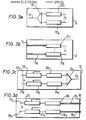
- the structure of a first example of input module 10 is shown in Figure 3A and consists of a demultiplexer 19 which demultiplexes k channel WDM signals on input fibre 11 onto k parallel channels, each of which includes a wavelength converter 20 1 -20 k .
- the wavelength converters each produce a respective different wavelength in response to the input signal applied thereto so that the device shown in Figure 3A provides one of N different output wavelengths to be coupled to the star couplers 14 as will be described hereinafter, where N corresponds to the total number of input or output modules (n+n').
- the wavelength converters may comprise all-optical devices or may include an opto-electrical detector that drives a tunable laser.
- each input module 12 receives k parallel electrical lines 13 1 -13 k that are connected to respective lasers that are tunable over the N different output wavelengths.
- the lasers which are typically laser diodes, produce output modulated signals at k different wavelengths, for the k input electrical signal channels.
- Specific examples of commercially available tunable lasers suitable for the system are listed on page 17 of the EFOC & N '93 paper, supra.
- the star couplers 14 1 -14 k each include N optical inputs and N optical outputs.
- the N inputs of each star coupler 14 are connected to receive individual different frequency outputs from each of the input modules.
- star coupler 14 1 has inputs connected to receive a respective different wavelength signal train from each of the input modules 10 1 -10 n and 12 1 -12 n '. In order to simplify the drawing, only the connections from input module 10 1 and 12 n ' are shown.
- connections from input module 10 1 and 12 n ' are shown with the other connections being omitted to simplify the drawing.
- the connections to star couplers 14 2 -14 k-1 have also been omitted for simplicity.
- the inputs are so arranged that each receives an individual wavelength from the groups of different wavelengths produced by each of the input modules 10 and 12.
- Each star coupler 14 operates in a manner well known per se so as to mix all the input signal trains and feed them to all of its outputs.
- a mixture of all of its inputs is applied to N outputs, namely to each of the output modules 15 1 -15 n , 16 1 -16 n '.
- each optical output module 15 consists of k inputs 22 1 -22 k which are individually connected to one output of each of the star couplers 14 1 -14 k .
- Each input 22 is connected to a receptor in the form of a tunable filter 23 1 -23 k which is individually tunable in order to select individual wavelengths from the mixture of signals applied to each input 22.
- tunable filters are described in detail on page 17 of the EFOC & N '93 paper, supra, and may comprise electro-mechanically tuned filters (e.g. Fabry-Perot etalon), acousto-optical or semiconductor filters.
- each star coupler connected to a corresponding one of the inputs 22, supplies a mixture of signals of different wavelengths selected from one of the outputs of each of the input modules 10, 12.
- each tunable filter 23 1 -23 k can be used to select an individual signal from one of the input modules on the basis of a wavelength selection.
- the tunable filters may be tuned individually by the application of an external control voltage from a control system (not shown).
- the output of each filter 23 1 -23 k is applied to a corresponding wavelength converter 24 1 -24 k .
- the wavelength converters produce signals that are combined by means of a passive combiner 25 to produce a k channel WDM signal on output fibre 17.
- selection of individual signals can be achieved for each output fibre 17 so that a selective cross-connection can be achieved between the input fibres 11 and output fibres 17.
- electrical signals applied to input modules 12 can be added into the k channel WDM signals produced at output fibres 17, thus lifting the electrical signal from the electronic layer of the network to the optical layer.
- FIG. 3D shows a structure for each electrical module 16, which allows optical signal trains to drop down from the optical layer to the electrical layer of the network.
- Each output module 16 consists of k input lines 26 1 -26 k which are applied to tunable filters 27 1 -27 k that function in a similar manner to the tunable filters 23 so as to select individual signal wavelengths.
- the outputs of the tunable filters 27 are applied to corresponding receivers 28 1 -28 k , typically in the form of photodiodes, which produce electrical signals corresponding to the signals of selected wavelength.
- the resulting k digital signal trains are applied to k output lines, which make up each output 18.
- signals of particular wavelengths are selected by the tunable filters 27 and are dropped down to electrical signals for use in the electronic layer of the network.
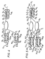
- FIG. 4 is an enlarged, partial illustration of the configuration of Figure 2, Figure 3A and Figure 3B, showing input modules 10 1 , 10 2 , star coupler 14 1 and output module 15 1 , the other components having been omitted to simplify the drawing.
- the input WDM signal is demultiplexed by demultiplexer 19 1 to provide k signals of wavelength ⁇ 1 - ⁇ k which are applied to respective wavelength converters 20 11 -20 1k .
- the wavelength converters produce respective outputs ⁇ i - ⁇ m .
- a similar set of signals is produced by input module 10 2 , comprising wavelengths ⁇ j - ⁇ n as shown in Figure 4.
- input module 10 2 comprising wavelengths ⁇ j - ⁇ n as shown in Figure 4.
- Each of the other input modules (not shown) produce similar outputs.
- each of its N inputs receives a signal from the first wavelength converter 20 11 -20 21 , etc. and the arrangement is set up so that each of the input wavelengths is different.
- N separate wavelengths are applied to the star coupler.
- ⁇ i ⁇ j the resulting mix of signals produced by star coupler 14 1 is applied to a single input of each of the output modules 15 1 -15 n , 16 1 -16 n '.
- the output module 15 1 as shown in Figure 4, it is not possible to select wavelength ⁇ i and ⁇ j from the input modules 10 1 , 10 2 simultaneously at the output module 15 1 since both of the signals are applied simultaneously to one of the filters 23. In Figure 4 this is shown as input filter 23 1 .
- the filter 23 1 can select only one of the wavelengths ⁇ i , ⁇ j and therefore, signal blocking of one of the wavelengths will occur.
- this shows an alternative configuration in which the star couplers of Figure 2 are replaced by a back plane bus.
- the individual input modules 10 1 -10 n , 12 1 -12 n have their k outputs connected individually to k parallel optical fibres 32 which form a fibre back plane.
- the output modules 15 1 -15 n and 16 1 -16 n have their respective k inputs selectively connected to the k fibres of the back plane.
- This arrangement is particularly suited to use with input modules of the form shown in Figure 5 since individual signal trains can be programmably applied to individual ones of the back plane fibres 32 and then selectively received by the output modules 15, 16 under the control of tunable filters 23, 27.
- This arrangement has the advantage that the individual modules can be arranged as units that can be plugged onto the back plane for example by using optical D-couplers.
- the described examples of the invention have the advantage that the number of elements that need to be controlled is much smaller as compared with the configuration shown in Figure 1.
- the component count is set out in the following table: Fig. 1 Fig. 2 Number of tunable filters 12 16 Number of tunable sources 4 4 Number of crosspoints 112 - Number of wavelength converters - 24 Total 128 44
- the wavelength converters in the input modules can be permanently set such that the output wavelength of a converter is always the same, the number of elements requiring control can be reduced to 36.
- optical star couplers of Figure 2 and the back plane bus of Figure 6 are inexpensive components as compared with the space switches shown in Figure 1.
- Packaged optical star couplers which are wavelength insensitive between 1300-1600 nm and as large as 144 x 144 have been reported and are thus suited to implement the invention. Since the optical star couplers are themselves inexpensive compared to the input and output modules shown in Figure 2, it is envisaged that not all the input and output modules need be attached at the time of commissioning the system so that the system can readily be upgraded in terms of its capacity thereafter.
- the described input and output modules both include wavelength converters, with the advantage that if a signal inversion occurs at the wavelength converter, two inversions occur, so that no signal inversion will occur in the final output of the cross-connect.
- each of the input optical fibres 11 carries k optical multiplex channels, but each input module 10, instead of providing k parallel channels, provides Q channels where: Q > 2k - 1
- the input modules 12 provide Q parallel channels and Q star couplers 14 are provided.
- Each of the output modules 15, 16 is provided with Q parallel channels.
- each input module 10 is similar to that shown in Figure 5 but with Q channels, and consists of an input fibre 11 that carries k input multiplexed channels, connected to a passive splitter 19 that has Q outputs coupled to Q tunable filters 31 1 - 31 Q which are respectively connected to wavelength converters 20 1 - 20 Q , in order to provide Q parallel outputs. From the foregoing, it will be seen that the channel redundancy of (Q - k) and the tunable nature of the various channels Q allows a strictly non-blocking configuration to be provided.
- FIG 8b which shows the input module 12, the arrangement has Q input channels connected to respective tunable lasers 21 1 - 21 Q .
- the remaining input channels Q - k
- the configuration of the output modules 15, 16 shown in Figures 8c, d is the same as that shown in Figures 3c, d except for the provision of Q parallel channels rather than k. It will be seen that by appropriate selection of the wavelength of operation of tunable filters 31 and 23, 27, a fully non-blocking architecture is provided by virtue of the (Q - k) channel redundancy.
- each optical cross-connect in accordance with the invention provides a decoupling between adjacent sections of the network.
- the separation of the N wavelengths used in the optical cross-connect need not be the same as the separation of the wavelengths ⁇ 1 - ⁇ k used on the link.
- the link wavelengths ⁇ 1 - ⁇ k may each be separated by 2 nm whereas the wavelengths ⁇ i , ⁇ n can be separated by 1nm, 2nm, 3nm or any other suitable spacing.
- the set of wavelengths used in the optical cross-connect is independent of the network and the number of trunk lines and the number of channels k used in the network itself.
- N can be chosen independently of k.
Description
- This invention relates to a cross-connect for an optical network.
- In order to cope with the increasing demand for subscriber services on telecommunication networks, digital optical transmission networks are being introduced in which local access networks, which typically route electrical signals, are interconnected by a fibre optic network. This has been facilitated by the introduction of the Synchronous Digital Hierarchy (SDH) standard that deals with the formatting of signals in Synchronous Transfer Modules (STM) which will allow a unified telecommunication infrastructure and provides improved flexibility by permitting electrical digital signals from the local access networks to be converted into optical signals and transmitted through the optical network.
- In order to upgrade the capacity of the optical network, Wavelength-Division-Multiplexing (WDM) techniques have been proposed, which permit the transmission capacity of a fibre link to be upgraded to the multi-Gbit/s range.
- Thus, it has been proposed to provide a multi-Gbit/s WDM network superimposed on the top level of a SDH network. For a fuller discussion, reference is directed to I. Hawker, "Evolution of Digital Optical Transmission Networks", BT Technol. J., Vol. 9, No. 4, October 1991, pp 43-56. It is proposed to include nodes in the WDM network to allow dynamic re-routing of WDM data streams. It is proposed that each node should include access ports to allow optical streams to be dropped to and added from lower levels of the network. It has been proposed that routing of the high bit rate streams is directly performed in the optical layer whereas processing of any of the streams is achieved in the electronic domain by dropping it to a lower layer of the network. Network management and administration is proposed to be achieved from a management unit which configures an optical cross-connect at each node according to traffic requirements. Thus, optical cross-connects (OXC's) constitute the routing nodes of the WDM transport network.
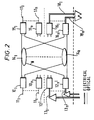
- A number of prior proposals have been made for the node architecture of the OXC and an example is given in Figure 1.
- Three input fibres 1, 2, 3 are connected at the node to output
fibres 4, 5, 6. Each of the fibres 1-3 carries four WDM wavelength channels, which are connected to the output fibres 4-6 by means of space switches X1-X4. In this example, the space switches are 4X4 matrices which thus have four inputs a-d and four outputs e-h that are optically interconnectable and are controlled by applied electrical signals (not shown). Such space switches are well known and include electrically controllable elements of variable refractive index to produce selective switching between the inputs and outputs. - The four optical channels of each input fibre 1-3 are applied to an input of each of the space switches X1-X4 and each is separately selected by means of a respective tunable filter F11, F21, F31, F41. Similarly, the various wavelength channels from fibres 2 and 3 are applied to respective inputs of the space switches through filters F12-F42, F13-F43. The fourth input of each space switch X1-X4 is connected to tunable
optical transmitter units 7 which produce optical signals of a single frequency in response to digital electrical signal streams from the lower electrical layer of the network, to allow electrical signals to be added into the optical network for transmission in the optical layer. The electrical signals may be SDH, PDH, ATM, X25 or any other suitable format, since the optical network can transmit the bit stream transparently in the optical domain. Similarly, the outputs h of each of the space switches X1-X4 are connected toreceiver units 8 that include photodetectors for producing electrical signals, so that digital data streams can be dropped out of the optical network into the lower, electrical layer. The outputs e-g of the space switches X1-X4 are respectively connected to the inputs to thefibres 4, 5 and 6 by means ofcombiners receivers - Firstly, the ultimate size of the OXC is limited by the size of the space switches. Currently, these are made in LiNbO3 or InP and are limited for practical purposes to 8X8. Also, for polarisation independent operation they typically require high switching voltages of the order of +/- 100 V and have long rise times > 100 ns. Furthermore, the devices are not at present hermetically sealed, and the material thereof tends to exhibit drift characteristics, so as to alter the performance with time.
- Secondly, a node configuration as shown in Figure 1 produces a loss of approximately 30 dB and the main contributor to the loss is the switch array. In order to overcome this problem, optical fibre amplifiers such as erbium doped fibre amplifiers need to be used to provide amplification.
- Thirdly, the node architecture exhibits blocking characteristics. It is not possible for the same wavelength channel from two of the input fibres to leave on the same output fibre.
- Another known switching arrangement is disclosed in EP-A-0 548 453. This describes a cross-connect having a plurality of switching mechanisms forming the coupling means for coupling a plurality of inputs and a plurality of outputs, whereby every signal applied to an input can be optionally switched to each output.
- The disclosed cross-connect includes signal splitters at the inputs for deriving individual signals at given frequencies from a group of input signals and signal combiners at the outputs for recombining signals at different frequencies from the plurality of coupling means.
- The non-modular topology of the disclosed cross-connect is such that, if it were desired to upgrade the line capacity of the cross-connect, all the splitters and combiners would need to be replaced and extra couplers would need to be included.
- The present invention provides an improved cross-connect, suitable for an optical network, which may overcome at least some of these problems. In accordance with the invention there is provided an optical cross-connect comprising a plurality of input means each for receiving a respective group of input signals and deriving in response to each signal of the group an individual optical signal of a respective given wavelength, a plurality of output means each including a plurality of receptors selectively responsive to respective ones of the wavelengths of said optical signals to provide an output signal for the output means, and a plurality of coupling means each for coupling a respective one of said optical signals, each of a different wavelength, from each of the input means, to a receptor of each of the output means characterised in that the input means are arranged in a plurality of modules each for receiving a group (k) of said input signals, said output means are arranged in a plurality of modules, and said modules are selectively connectible to the coupling means.
- In accordance with the invention, it is possible to route signals of the same wavelength from different input means to a particular one of the output means. Furthermore, the losses involved may be substantially reduced.
- In one form, the plurality of coupling means comprises a plurality of star couplers, and in another form comprises a plurality of optical bus lines to which the input and output means may be selectively added and removed as modules.
- The input signals may be electrical or optical and the plurality of input means may be configured to process optical and electrical signals, to allow electrical signals to be added into the optical signal traffic. Similarly, at least one of the output means may produce electrical output signals to allow optical signals to be dropped to an electrical network.
- Furthermore, an improved non-blocking arrangement may be provided, in which a plurality of the input means are each operative to receive a respective group (k) of input signals and derive in response to each signal of the group an individual optical signal of a respective given wavelength, the individual output signals being provided on selected ones of a plurality of output channels greater than k, a plurality of the output means each including a plurality of receptors greater in number than k, are selectively responsive to respective ones of the wavelengths of said optical signals to provide an output signal for the output means, and a plurality of the coupling means greater in number than k, are each operative to couple a respective one of said optical signals, each of a different wavelength, from each of the input means, to a respective receptor of each of the output means.
- In order that the invention may be more fully understood an embodiment thereof will now be described by way of example, reference being had to the accompanying drawings in which:
- Figure 1 is a schematic block diagram of a prior OXC, described hereinbefore;
- Figure 2 is a schematic block diagram of an optical cross-connect in accordance with the invention;
- Figure 3 illustrates schematically input and output modules of the cross-connect shown in Figure 2;
- Figure 4 illustrates signal blocking in the arrangement of Figures 2 and 3;
- Figure 5 is a schematic block diagram of the cross-connect with an alternative form of input module which avoids signal blocking;
- Figure 6 is a schematic block diagram of an alternative form of cross-connect in accordance with the invention, which utilises a back plane bus;
- Figure 7 illustrates a further optical cross-connect in accordance with the invention; and
- Figure 8 illustrates schematically input and output modules of the cross-connect shown in Figure 7.
-
- Referring to Figure 2, the OXC in accordance with the invention is configured for use at a node in a WDM hierarchical telecommunication system that includes an optical layer overlying various electronic layers.
- The OXC includes a number of input means in the form of input modules 101-10n to which optical fibres 111-11n are connected, the optical fibres carrying k channel WDM signals. The OXC also receives inputs from the electronic layer that are applied to input modules 121-12n' . Each
input module 12 receives kelectrical lines 13 carrying electrical input digital signals. - As will be explained in more detail hereinafter, signals corresponding to the k channels of each electrical and optical input, are connected by means of k star couplers 141-14k to a plurality of output means in the form of optical output modules 151-15n and electronic output modules 161-16n'. The output modules 151-15n provide k channel WDM optical signals on output fibres 171-17n. The
output modules 16 provide electrical outputs that can be dropped down to the electronic layer of the network on lines 181-18n'. - The structure of a first example of
input module 10 is shown in Figure 3A and consists of ademultiplexer 19 which demultiplexes k channel WDM signals on input fibre 11 onto k parallel channels, each of which includes a wavelength converter 201-20k. The wavelength converters each produce a respective different wavelength in response to the input signal applied thereto so that the device shown in Figure 3A provides one of N different output wavelengths to be coupled to thestar couplers 14 as will be described hereinafter, where N corresponds to the total number of input or output modules (n+n'). The wavelength converters may comprise all-optical devices or may include an opto-electrical detector that drives a tunable laser. Examples of specific wavelength converters currently available are listed in "Photonic terabit/s networks and their key components" H.R. van As, IBM Research Div (Rüschlikon) 11th Annual Conference on European Fibre Optic Communications and Networks (EFOC & N '93) June 30 - July 1993 pp 13-20, and in particular onpage 18. - The structure of each
input module 12 for electrical signals is shown in more detail in Figure 3B. Eachinput module 12 receives k parallel electrical lines 131-13k that are connected to respective lasers that are tunable over the N different output wavelengths. Thus the lasers, which are typically laser diodes, produce output modulated signals at k different wavelengths, for the k input electrical signal channels. Specific examples of commercially available tunable lasers suitable for the system are listed onpage 17 of the EFOC & N '93 paper, supra. - Referring to Figure 1, the star couplers 141-14k each include N optical inputs and N optical outputs. The N inputs of each
star coupler 14 are connected to receive individual different frequency outputs from each of the input modules. Thus, referring to Figure 2,star coupler 141 has inputs connected to receive a respective different wavelength signal train from each of the input modules 101-10n and 121-12n'. In order to simplify the drawing, only the connections frominput module 101 and 12n' are shown. Similarly, for thestar coupler 14k, connections frominput module 101 and 12n' are shown with the other connections being omitted to simplify the drawing. The connections to star couplers 142-14k-1 have also been omitted for simplicity. For each of thestar couplers 14, the inputs are so arranged that each receives an individual wavelength from the groups of different wavelengths produced by each of theinput modules - Each
star coupler 14 operates in a manner well known per se so as to mix all the input signal trains and feed them to all of its outputs. Thus, considering forexample star coupler 141, a mixture of all of its inputs is applied to N outputs, namely to each of the output modules 151-15n, 161-16n'. - The nature of each of the output modules will now be described with reference to Figure 3. Referring to Figure 3C, the structure of each
optical output module 15 is shown. The module consists of k inputs 221-22k which are individually connected to one output of each of the star couplers 141-14k. Each input 22 is connected to a receptor in the form of a tunable filter 231-23k which is individually tunable in order to select individual wavelengths from the mixture of signals applied to each input 22. Commercially available tunable filters are described in detail onpage 17 of the EFOC & N '93 paper, supra, and may comprise electro-mechanically tuned filters (e.g. Fabry-Perot etalon), acousto-optical or semiconductor filters. - It will be recalled that each star coupler, connected to a corresponding one of the inputs 22, supplies a mixture of signals of different wavelengths selected from one of the outputs of each of the
input modules passive combiner 25 to produce a k channel WDM signal onoutput fibre 17. - Thus, by suitable selection of the pass frequencies of the
filters 23, selection of individual signals can be achieved for eachoutput fibre 17 so that a selective cross-connection can be achieved between the input fibres 11 andoutput fibres 17. Moreover, electrical signals applied to inputmodules 12 can be added into the k channel WDM signals produced atoutput fibres 17, thus lifting the electrical signal from the electronic layer of the network to the optical layer. - Figure 3D shows a structure for each
electrical module 16, which allows optical signal trains to drop down from the optical layer to the electrical layer of the network. Eachoutput module 16 consists of k input lines 261-26k which are applied to tunable filters 271-27k that function in a similar manner to thetunable filters 23 so as to select individual signal wavelengths. The outputs of the tunable filters 27 are applied to corresponding receivers 281-28k, typically in the form of photodiodes, which produce electrical signals corresponding to the signals of selected wavelength. The resulting k digital signal trains are applied to k output lines, which make up eachoutput 18. Thus, signals of particular wavelengths are selected by the tunable filters 27 and are dropped down to electrical signals for use in the electronic layer of the network. - A problem with the configuration described so far is that signal blocking can occur at some of the
outputs 17. This can be understood from Figure 4 which is an enlarged, partial illustration of the configuration of Figure 2, Figure 3A and Figure 3B, showinginput modules star coupler 141 andoutput module 151, the other components having been omitted to simplify the drawing. - Referring to input
module 101, the input WDM signal is demultiplexed bydemultiplexer 191 to provide k signals of wavelength λ1-λk which are applied to respective wavelength converters 2011-201k. The wavelength converters produce respective outputs λi-λm. - A similar set of signals is produced by
input module 102, comprising wavelengths λj-λn as shown in Figure 4. Each of the other input modules (not shown) produce similar outputs. - Considering now the
star coupler 141, each of its N inputs receives a signal from the first wavelength converter 2011-2021, etc. and the arrangement is set up so that each of the input wavelengths is different. Thus N separate wavelengths are applied to the star coupler. Accordingly, referring to Figure 4, λi≠λj. As previously explained, the resulting mix of signals produced bystar coupler 141 is applied to a single input of each of the output modules 151-15n, 161-16n'. Thus, considering theoutput module 151 as shown in Figure 4, it is not possible to select wavelength λi and λj from theinput modules output module 151 since both of the signals are applied simultaneously to one of thefilters 23. In Figure 4 this is shown asinput filter 231. Thefilter 231 can select only one of the wavelengths λi, λj and therefore, signal blocking of one of the wavelengths will occur. - This problem is overcome by the configuration shown in Figure 5, in which a different form of the input module 10' is provided. Referring to input module 10'1 the input WDM signals applied on input fibre 111 are fed to a beam splitter 301 that provides k parallel channel outputs each of which is fed to a tunable filter 3111-311k that in turn are connected to individual wavelength converters 2011-201k. Thus, by tuning the individual filters 3111-311k, the different input signals λ1-λk can be applied to different ones of the k channels selectively. The wavelength converters 2011-201k then produce appropriate signals for the inputs of the
star couplers 14. In Figure 5, the first twostar couplers output module 151 that contains wavelength λi from input module 10'1 and λj from input module 10'2, if, as previously described with reference to Figure 4, these signals were applied to the inputs of a single one of the star couplers, blocking would occur. However, as shown in Figure 5, the tunable filter 3122 is adjusted such that wavelength converter 2022 (rather than converter 2021) produces the output wavelength λj. Consequently, the signal of wavelength λj is applied to starcouplers 142 and hence to the second input of theoutput module 151. Thus, the signals of wavelength λi and λj can be selected by thetunable filters output module 151. In this way, signal blocking is avoided. - Referring to Figure 6, this shows an alternative configuration in which the star couplers of Figure 2 are replaced by a back plane bus. Thus, the individual input modules 101-10n, 121-12n have their k outputs connected individually to k parallel
optical fibres 32 which form a fibre back plane. The output modules 151-15n and 161-16n have their respective k inputs selectively connected to the k fibres of the back plane. This arrangement is particularly suited to use with input modules of the form shown in Figure 5 since individual signal trains can be programmably applied to individual ones of theback plane fibres 32 and then selectively received by theoutput modules tunable filters 23, 27. This arrangement has the advantage that the individual modules can be arranged as units that can be plugged onto the back plane for example by using optical D-couplers. - The described examples of the invention have the advantage that the number of elements that need to be controlled is much smaller as compared with the configuration shown in Figure 1. Considering an example of the OXC of Figure 2, when compared with that of Figure 1, when the number of wavelengths k = 4 and the number of input and output optical lines is 3, the component count is set out in the following table:
Fig. 1 Fig. 2 Number of tunable filters 12 16 Number of tunable sources 4 4 Number of crosspoints 112 - Number of wavelength converters - 24 Total 128 44 - Furthermore, since the wavelength converters in the input modules can be permanently set such that the output wavelength of a converter is always the same, the number of elements requiring control can be reduced to 36.
- The optical star couplers of Figure 2 and the back plane bus of Figure 6 are inexpensive components as compared with the space switches shown in Figure 1. Packaged optical star couplers which are wavelength insensitive between 1300-1600 nm and as large as 144 x 144 have been reported and are thus suited to implement the invention. Since the optical star couplers are themselves inexpensive compared to the input and output modules shown in Figure 2, it is envisaged that not all the input and output modules need be attached at the time of commissioning the system so that the system can readily be upgraded in terms of its capacity thereafter. The described input and output modules both include wavelength converters, with the advantage that if a signal inversion occurs at the wavelength converter, two inversions occur, so that no signal inversion will occur in the final output of the cross-connect.
- An embodiment of the invention will now be described in which an alternative way of avoiding channel blocking is achieved. Referring to Figure 7, the structure is generally similar to that shown in Figure 2 and like parts are given the same reference numbers. Each of the input optical fibres 11 carries k optical multiplex channels, but each
input module 10, instead of providing k parallel channels, provides Q channels where: - Similarly, the
input modules 12 provide Q parallel channels andQ star couplers 14 are provided. Each of theoutput modules - The various input and
output modules input module 10 is similar to that shown in Figure 5 but with Q channels, and consists of an input fibre 11 that carries k input multiplexed channels, connected to apassive splitter 19 that has Q outputs coupled to Q tunable filters 311 - 31Q which are respectively connected to wavelength converters 201 - 20Q, in order to provide Q parallel outputs. From the foregoing, it will be seen that the channel redundancy of (Q - k) and the tunable nature of the various channels Q allows a strictly non-blocking configuration to be provided. - Referring now to Figure 8b which shows the
input module 12, the arrangement has Q input channels connected to respective tunable lasers 211 - 21Q. For a system which provides k input channels, the remaining input channels (Q - k) can be used to provide test signals. The configuration of theoutput modules tunable filters 31 and 23, 27, a fully non-blocking architecture is provided by virtue of the (Q - k) channel redundancy. Whilst this non-blocking arrangement has been described for use with thestar couplers 14, it will be appreciated that it can also be used in connection with a back plane bus as shown in Figure 6, but utilising Q back plane channels. Thus the various modules of Figure 8, could be used with a Q channel back plane bus. - Since the wavelengths used in the cross-connect according to the invention are selected independently of the wavelengths used in the optical network itself, it is not necessary to control the preciseness of wavelength throughout the entire network but only on a link-by-link basis, since each optical cross-connect in accordance with the invention provides a decoupling between adjacent sections of the network.
- Also, the separation of the N wavelengths used in the optical cross-connect need not be the same as the separation of the wavelengths λ1-λk used on the link. For example, the link wavelengths λ1-λk may each be separated by 2 nm whereas the wavelengths λi, λn can be separated by 1nm, 2nm, 3nm or any other suitable spacing.
- Thus, the set of wavelengths used in the optical cross-connect is independent of the network and the number of trunk lines and the number of channels k used in the network itself. Thus, N can be chosen independently of k.
Claims (20)
- An optical cross-connect comprising:a plurality of input means (10, 12) each for receiving a respective group of input signals (11, 13) and deriving in response to each signal of the group an individual optical signal (λi) of a respective given wavelength,a plurality of output means (15, 16) each including a plurality of receptors (23, 27) selectively responsive to respective ones of the wavelengths of said optical signals to provide an output signal for the output means, anda plurality of coupling means (14, 32) each for coupling a respective one of said optical signals, each of a different wavelength, from each of the input means, to a respective receptor of each of the output means
characterised in that
the input means (10, 12) are arranged in a plurality (N) of modules each for receiving a group (k) of said input signals,
said output means (15, 16) are arranged in a plurality of modules, and
said modules are selectively connectible to the coupling means. - An optical cross-connect according to claim 1 wherein said input signals comprise multiplexed optical signals and at least some of said input means (10) include means responsive to the multiplexed optical signals to produce said individual optical signals of respective given wavelengths.
- An optical cross-connect according to claim 2 wherein said multiplexed optical signals comprise WDM signals.
- An optical cross-connect according to claim 3 wherein the input means comprises a WDM demultiplexer (19) for demultiplexing the input WDM signals, and a plurality of wavelength converters (20) responsive respectively to the demultiplexed signals for producing said individual optical signals.
- An optical cross-connect according to claim 3 including means (30, 31) for selectively controlling which of said individual optical signals from the respective input means are coupled to a particular one of the coupling means.
- An optical cross-connect according to claim 5 wherein at least some of said input means includes beam splitting means (30) for splitting the input optical signals into a plurality of paths, and tunable filters (31) associated with the paths for selecting the individual WDM signals respectively.
- An optical cross-connect according to claim 6 including wavelength converters (20) connected to the outputs of the tunable filters (31) respectively.
- An optical cross-connect according to any one of claims 2 to 6 wherein at least some of the output means include a respective means (25) for combining the outputs of the receptors to provide the output signal.
- An optical cross-connect according to claim 8 including wavelength converters (24) connected to the outputs of the outputs of the receptors (23).
- An optical cross-connect according to any preceding claim wherein at least one group of said input signals comprise electrical signals and the input means (12) that receives the electrical signals includes a plurality of tunable lasers (21) operative to generate corresponding optical signals at said different wavelengths.
- An optical cross-connect according to any preceding claim wherein at least one of the output means includes photodetectors (28) connected to the receptors (27) thereof for producing a plurality of output electrical signals.
- An optical cross-connect according to any preceding claim wherein the receptors comprise tunable filters.
- An optical cross-connect according to any preceding claim wherein said plurality of coupling means comprises a plurality of star couplers (14).
- An optical cross-connect according to any preceding claim wherein said plurality of coupling means comprises a plurality of bus lines (32), with the optical signals of different wavelength from each input means being coupled to the bus lines, and the receptors of each output means being coupled to the bus lines.
- An optical cross-connect according to claim 14 wherein said modules of said input means and said output means (10, 12, 15, 16) are selectively addable to and removable from connection from the bus lines.
- An optical cross-connect according to any preceding claim wherein the wavelengths of the individual optical signals are selectable independently of the wavelengths of the input signals.
- An optical cross-connect according to any preceding claim wherein a plurality of the input means (10,12) are each operative to receive a respective group (k) of input signals and derive in response to each signal of the group an individual optical signal of a respective given wavelength the individual output signals being provided on selected ones of a plurality of output channels greater than k, a plurality of the output means (15, 16) each including a plurality of receptors greater in number than k, are selectively responsive to respective ones of the wavelengths of said optical signals to provide an output signal for the output means, and a plurality of the coupling means (14, 32) greater in number than k, are each operative to couple a respective one of said optical signals, each of a different wavelength, from each of the input means, to a respective receptor of each of the output means.
- An optical cross-connect according to claim 17 wherein the input means (10, 12) each include Q channels where
- An optical cross-connect according to claim 18 including Q of said coupling means (14, 32).
- An optical cross-connect according to claim 17 or 18 including Q of said receptors (23, 27) for each of said output means (15, 16).
Priority Applications (1)
| Application Number | Priority Date | Filing Date | Title |
|---|---|---|---|
| EP94930310A EP0733298B1 (en) | 1993-11-08 | 1994-10-24 | A cross-connect for an optical network |
Applications Claiming Priority (6)
| Application Number | Priority Date | Filing Date | Title |
|---|---|---|---|
| EP93308884 | 1993-11-08 | ||
| EP93308884 | 1993-11-08 | ||
| GB9406208A GB9406208D0 (en) | 1994-03-29 | 1994-03-29 | A cross-connect for an optical network |
| GB9406208 | 1994-03-29 | ||
| EP94930310A EP0733298B1 (en) | 1993-11-08 | 1994-10-24 | A cross-connect for an optical network |
| PCT/GB1994/002330 WO1995013687A1 (en) | 1993-11-08 | 1994-10-24 | A cross-connect for an optical network |
Publications (2)
| Publication Number | Publication Date |
|---|---|
| EP0733298A1 EP0733298A1 (en) | 1996-09-25 |
| EP0733298B1 true EP0733298B1 (en) | 2000-05-03 |
Family
ID=27235514
Family Applications (1)
| Application Number | Title | Priority Date | Filing Date |
|---|---|---|---|
| EP94930310A Expired - Lifetime EP0733298B1 (en) | 1993-11-08 | 1994-10-24 | A cross-connect for an optical network |
Country Status (1)
| Country | Link |
|---|---|
| EP (1) | EP0733298B1 (en) |
-
1994
- 1994-10-24 EP EP94930310A patent/EP0733298B1/en not_active Expired - Lifetime
Also Published As
| Publication number | Publication date |
|---|---|
| EP0733298A1 (en) | 1996-09-25 |
Similar Documents
| Publication | Publication Date | Title |
|---|---|---|
| US5889600A (en) | Cross-connect for an optical network | |
| US6542268B1 (en) | Optical channel cross connect for telecommunication systems in wdm technology (wavelength division multiplexing) having a double spatial switching structure of optical flows strictly not blocking and interposed functional units operating on single channels | |
| US10338320B2 (en) | Scalable optical switches and switching modules | |
| US5712932A (en) | Dynamically reconfigurable WDM optical communication systems with optical routing systems | |
| KR100375276B1 (en) | Modular optical bridge-connection structure with optical wavelength switching | |
| US6519060B1 (en) | Synchronous optical network in frequency domain | |
| AU626985B2 (en) | Communication network | |
| US5550818A (en) | System for wavelength division multiplexing/asynchronous transfer mode switching for network communication | |
| US6333799B1 (en) | Hybrid wavelength-interchanging cross-connect | |
| US6690848B2 (en) | Metropolitan photonic switch | |
| US4821255A (en) | Cross-connection of wavelength-division-multiplexed high speed optical channels | |
| CA2285128C (en) | Switch for optical signals | |
| US5739935A (en) | Modular optical cross-connect architecture with optical wavelength switching | |
| US5623356A (en) | Combined wavelength router and switch apparatus for use in a wavelength division multiplexed optical communication system | |
| Kuznetsov et al. | A next-generation optical regional access network | |
| CA2241106A1 (en) | System and method for photonic facility and line protection switching | |
| Stern | Linear lightwave networks: How far can they go? | |
| Gerstel | On the future of wavelength routing networks | |
| Nooruzzaman et al. | Low-cost hybrid ROADM architectures for scalable C/DWDM metro networks | |
| US6429955B1 (en) | Optical network | |
| JP3574754B2 (en) | Optical path cross connect device | |
| US5694499A (en) | Optical crossconnect | |
| US20040258411A1 (en) | Node for an optical network | |
| EP0733298B1 (en) | A cross-connect for an optical network | |
| EP1017243A2 (en) | Optical switch and optical switched network |
Legal Events
| Date | Code | Title | Description |
|---|---|---|---|
| PUAI | Public reference made under article 153(3) epc to a published international application that has entered the european phase |
Free format text: ORIGINAL CODE: 0009012 |
|
| 17P | Request for examination filed |
Effective date: 19960328 |
|
| AK | Designated contracting states |
Kind code of ref document: A1 Designated state(s): BE CH DE DK ES FR GB IT LI NL SE |
|
| 17Q | First examination report despatched |
Effective date: 19971218 |
|
| GRAG | Despatch of communication of intention to grant |
Free format text: ORIGINAL CODE: EPIDOS AGRA |
|
| GRAG | Despatch of communication of intention to grant |
Free format text: ORIGINAL CODE: EPIDOS AGRA |
|
| GRAH | Despatch of communication of intention to grant a patent |
Free format text: ORIGINAL CODE: EPIDOS IGRA |
|
| GRAH | Despatch of communication of intention to grant a patent |
Free format text: ORIGINAL CODE: EPIDOS IGRA |
|
| GRAA | (expected) grant |
Free format text: ORIGINAL CODE: 0009210 |
|
| AK | Designated contracting states |
Kind code of ref document: B1 Designated state(s): BE CH DE DK ES FR GB IT LI NL SE |
|
| PG25 | Lapsed in a contracting state [announced via postgrant information from national office to epo] |
Ref country code: NL Free format text: LAPSE BECAUSE OF FAILURE TO SUBMIT A TRANSLATION OF THE DESCRIPTION OR TO PAY THE FEE WITHIN THE PRESCRIBED TIME-LIMIT Effective date: 20000503 Ref country code: LI Free format text: LAPSE BECAUSE OF FAILURE TO SUBMIT A TRANSLATION OF THE DESCRIPTION OR TO PAY THE FEE WITHIN THE PRESCRIBED TIME-LIMIT Effective date: 20000503 Ref country code: CH Free format text: LAPSE BECAUSE OF FAILURE TO SUBMIT A TRANSLATION OF THE DESCRIPTION OR TO PAY THE FEE WITHIN THE PRESCRIBED TIME-LIMIT Effective date: 20000503 |
|
| REG | Reference to a national code |
Ref country code: CH Ref legal event code: EP |
|
| REF | Corresponds to: |
Ref document number: 69424311 Country of ref document: DE Date of ref document: 20000608 |
|
| REG | Reference to a national code |
Ref country code: GB Ref legal event code: 732E |
|
| REG | Reference to a national code |
Ref country code: ES Ref legal event code: FG2A Ref document number: 2145846 Country of ref document: ES Kind code of ref document: T3 |
|
| ITF | It: translation for a ep patent filed |
Owner name: JACOBACCI & PERANI S.P.A. |
|
| PG25 | Lapsed in a contracting state [announced via postgrant information from national office to epo] |
Ref country code: SE Free format text: LAPSE BECAUSE OF FAILURE TO SUBMIT A TRANSLATION OF THE DESCRIPTION OR TO PAY THE FEE WITHIN THE PRESCRIBED TIME-LIMIT Effective date: 20000803 Ref country code: DK Free format text: LAPSE BECAUSE OF FAILURE TO SUBMIT A TRANSLATION OF THE DESCRIPTION OR TO PAY THE FEE WITHIN THE PRESCRIBED TIME-LIMIT Effective date: 20000803 |
|
| ET | Fr: translation filed | ||
| NLV1 | Nl: lapsed or annulled due to failure to fulfill the requirements of art. 29p and 29m of the patents act | ||
| REG | Reference to a national code |
Ref country code: CH Ref legal event code: PL |
|
| PLBE | No opposition filed within time limit |
Free format text: ORIGINAL CODE: 0009261 |
|
| STAA | Information on the status of an ep patent application or granted ep patent |
Free format text: STATUS: NO OPPOSITION FILED WITHIN TIME LIMIT |
|
| 26N | No opposition filed | ||
| PGFP | Annual fee paid to national office [announced via postgrant information from national office to epo] |
Ref country code: BE Payment date: 20011004 Year of fee payment: 8 |
|
| PGFP | Annual fee paid to national office [announced via postgrant information from national office to epo] |
Ref country code: ES Payment date: 20011010 Year of fee payment: 8 |
|
| REG | Reference to a national code |
Ref country code: GB Ref legal event code: IF02 |
|
| PG25 | Lapsed in a contracting state [announced via postgrant information from national office to epo] |
Ref country code: ES Free format text: LAPSE BECAUSE OF NON-PAYMENT OF DUE FEES Effective date: 20021025 |
|
| PG25 | Lapsed in a contracting state [announced via postgrant information from national office to epo] |
Ref country code: BE Free format text: LAPSE BECAUSE OF NON-PAYMENT OF DUE FEES Effective date: 20021031 |
|
| BERE | Be: lapsed |
Owner name: BRITISH *TELECOMMUNICATIONS P.L.C. Effective date: 20021031 |
|
| REG | Reference to a national code |
Ref country code: ES Ref legal event code: FD2A Effective date: 20031112 |
|
| PG25 | Lapsed in a contracting state [announced via postgrant information from national office to epo] |
Ref country code: IT Free format text: LAPSE BECAUSE OF NON-PAYMENT OF DUE FEES Effective date: 20051024 |
|
| PGFP | Annual fee paid to national office [announced via postgrant information from national office to epo] |
Ref country code: FR Payment date: 20080922 Year of fee payment: 15 |
|
| PGFP | Annual fee paid to national office [announced via postgrant information from national office to epo] |
Ref country code: GB Payment date: 20080919 Year of fee payment: 15 |
|
| PGFP | Annual fee paid to national office [announced via postgrant information from national office to epo] |
Ref country code: DE Payment date: 20080923 Year of fee payment: 15 |
|
| REG | Reference to a national code |
Ref country code: FR Ref legal event code: ST Effective date: 20100630 |
|
| PG25 | Lapsed in a contracting state [announced via postgrant information from national office to epo] |
Ref country code: FR Free format text: LAPSE BECAUSE OF NON-PAYMENT OF DUE FEES Effective date: 20091102 Ref country code: DE Free format text: LAPSE BECAUSE OF NON-PAYMENT OF DUE FEES Effective date: 20100501 |
|
| PG25 | Lapsed in a contracting state [announced via postgrant information from national office to epo] |
Ref country code: GB Free format text: LAPSE BECAUSE OF NON-PAYMENT OF DUE FEES Effective date: 20091024 |