EP1100234A2 - ATM service disruption measurement - Google Patents
ATM service disruption measurement Download PDFInfo
- Publication number
- EP1100234A2 EP1100234A2 EP00309671A EP00309671A EP1100234A2 EP 1100234 A2 EP1100234 A2 EP 1100234A2 EP 00309671 A EP00309671 A EP 00309671A EP 00309671 A EP00309671 A EP 00309671A EP 1100234 A2 EP1100234 A2 EP 1100234A2
- Authority
- EP
- European Patent Office
- Prior art keywords
- data
- time
- guard
- timer
- cells
- Prior art date
- Legal status (The legal status is an assumption and is not a legal conclusion. Google has not performed a legal analysis and makes no representation as to the accuracy of the status listed.)
- Granted
Links
Images


Classifications
-
- H—ELECTRICITY
- H04—ELECTRIC COMMUNICATION TECHNIQUE
- H04Q—SELECTING
- H04Q11/00—Selecting arrangements for multiplex systems
- H04Q11/04—Selecting arrangements for multiplex systems for time-division multiplexing
- H04Q11/0428—Integrated services digital network, i.e. systems for transmission of different types of digitised signals, e.g. speech, data, telecentral, television signals
- H04Q11/0478—Provisions for broadband connections
-
- H—ELECTRICITY
- H04—ELECTRIC COMMUNICATION TECHNIQUE
- H04L—TRANSMISSION OF DIGITAL INFORMATION, e.g. TELEGRAPHIC COMMUNICATION
- H04L12/00—Data switching networks
- H04L12/54—Store-and-forward switching systems
- H04L12/56—Packet switching systems
- H04L12/5601—Transfer mode dependent, e.g. ATM
- H04L2012/5625—Operations, administration and maintenance [OAM]
- H04L2012/5627—Fault tolerance and recovery
-
- H—ELECTRICITY
- H04—ELECTRIC COMMUNICATION TECHNIQUE
- H04L—TRANSMISSION OF DIGITAL INFORMATION, e.g. TELEGRAPHIC COMMUNICATION
- H04L12/00—Data switching networks
- H04L12/54—Store-and-forward switching systems
- H04L12/56—Packet switching systems
- H04L12/5601—Transfer mode dependent, e.g. ATM
- H04L2012/5628—Testing
Definitions
- the present invention relates to the measurement of a time interval during which asynchronous transfer mode (ATM) transmission of data in a data transmission channel is disrupted.
- ATM asynchronous transfer mode
- a process called "protection switching” is used in linear and ring Synchronous Digital Hierarchy (SDH) networks, sometimes called Synchronous Optical Networks (SONET), in order to re-establish asynchronous transfer mode (ATM) transmission of data when the performance of a data transmission channel is degraded, the channel is cut, or otherwise disrupted. This can happen because of a cut to an optical fibre, or equipment failure at end points or switching points in the network. Such service disruption events can lead to an unrecoverable loss of data, and so it is important to be able to quantify the possible loss up until the time protection switching re-establishes error-free transmission of data. Such testing is often done when an SDH network or part of a network is installed and commissioned.
- SDH Synchronous Digital Hierarchy
- SONET Synchronous Optical Networks
- ATM data transmission consists of identifiable data cells transmitted in a defined order along an ATM Virtual Channel, i.e. a group of ATM data cells each having the same header. More than one such ATM virtual channel may undergo protection switching in a service disruption event.
- a service disruption event can be simulated in testing by transmitting ATM data along one or more virtual channels, the data having a data transmission rate comparable to the expected utilisation of the virtual channels, and then by disconnecting or breaking a fibre or by disabling equipment using the virtual channels, such as an ATM switch.
- the so-called "physical layer" the fibres and connecting equipment, can be reconfigured very quickly to establish new virtual channels, the data cell stream may suffer impairments, such as erroneous detected data in a cell, lost cells, or misinserted cells where the ordering of received cells is incorrect.
- One simple way of estimating if the protection switching is within the recommended limits is to count the number of lost or errored cells, and then divide this number by the cell transmission rate. If 100 cells are lost or errored at a transmission rate of 100,000 cells per second, then the duration of the service disruption event can be estimated as 10 ms. It has been found, however, that this simple way of estimating the extent of a service disruption event, overestimates the effectiveness of protection switching in reestablishing data transmission in an ATM network.
- a protection switching event will often include a period of increased error rate for data in cells, for example due to impaired signal-to-noise levels, or increased timing jitter, prior to a complete loss of cells. Some cells can be lost completely, and others can be in the wrong order or misinserted when the data cells are received. In all of these cases, the data cells have become corrupted.
- the data analyzer may therefore characterise corrupted data cells according to whether cells have been errored, for example, comprising data which is in error according to a cyclic redundancy check (CRC), or lost or misinserted.
- CRC cyclic redundancy check
- the service disruption event therefore lasts at least from the last uncorrupted data cells prior to the switching event up until the time when data cells are again consistently uncorrupted.
- the guard timer therefore accommodates the observed performance of switching events, in which isolated uncorrupted cells or groups of consecutive uncorrupted cells can be transmitted, so that the duration of the service disruption event is measured by the disruption timer as continuing even when some correct data cells are being transmitted.
- the predetermined guard time can then be selected empirically according to the performance of typical protection switching events.
- the duration of the service disruption event may be a time measured from a start time prior to detection by the data analyzer of the first corrupted data cell until an end time at or following the consistent resumption of uncorrupted data cells.
- the end time may be at a time prior to the time at which the guard timer has reached a time at least as great as the guard time in step g).
- Including a proportion of an appropriate predetermined guard time in the measured disruption time, whether at the beginning and/or the end of the measured period, provides the benefit that the measurement does not underestimate the performance of the switching event in comparison with the performance recommended under international standards.
- the start time may be a time no later than the last uncorrupted data cell before the service disruption event, and in a preferred embodiment of the invention, the start time may be in advance of this time, for example being a time which precedes said last uncorrupted data cell by no more than the guard time.
- the guard time then serves the purpose of providing a conservative measure of both the start and the end of the service disruption event.
- the start time may be a time that may precede said last uncorrupted data cell by more than the guard time when there is a gap in the stream of data cells following the last uncorrupted data cell greater than the guard time.
- step e) said subsequent data cell may be the second consecutive data cell that is not corrupted as detected by the data analyzer.
- the guard time is timed starting from the detection of the last corrupted data cell, rather than, for example, the arrival of the next and first uncorrupted data cell towards the end of the protection switching event.
- step b) is performed using the ITU-T Recommendation 0.191.
- a data analyzer system for measuring the duration of a service disruption event in an asynchronous transfer mode (ATM) data transmission channel carrying an ATM stream of identifiable data cells in a defined order, the data analyzer system comprising error detection means for determining whether or not any of the data cells have been corrupted in transmission through the data transmission channel when the transmission is disrupted, and a disruption timer for timing the service disruption event starting when a first corrupted data cell is detected by the error detection means, characterised in that the data analyzer system has a guard timer for timing a guard time interval when uncorrupted data cells are detected by the error detection means, and control means for controlling the operation of the disruption timer and guard timer in response to the determination by the error detection means of whether or not any data cells have been corrupted, wherein the disruption timer is operable to time a service disruption event from the start of the disruption event until the guard timer has timed a predetermined guard time, and the guard timer is operable to time the guard time interval when corrupt
- ATM asynchronous transfer mode
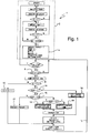
- Figure 1 is a flow diagram 1 taken from the standard ITU-T Recommendation 0.191. This is used to detect errors in an ATM data channel during a protection switching event.
- the diagram 1 is well understood by those skilled in the art and so will be described briefly.
- a protection switching test of ATM network equipment is normally done when the equipment is out of service.
- a test stream of ATM data cells therefore needs to be provided, and it is best if this test stream matches closely the expected data traffic when the equipment is in service.
- the test stream consists of data cells that have consecutively incremented header serial numbers (SN).
- SNRef The expected serial number of a data cell arriving at the test equipment.
- the values Ndiff and Odiff are defined by:
- S is a cyclic redundancy check (CRC) on data in the data cell.
- CRC cyclic redundancy check
- the flow diagram 1 initialises 4 these and other terms, and if a data cell arrives within an expected time 6, the results of the synchronisation are analyzed, starting at step 8, which checks if the CRC has detected a data error in a cell. If so, then in step 10 an error counter value E1 is incremented by one. The test sequence then loops back 12 to await the next data cell. If this has no errors detected by the CRC, then the next check at step 14 is whether the sequence number was found to be correct. If so, then the algorithm proceeds to step 16 where it produces as an output the number of detected error cells, which is here just the non-zero value of E1.
- step 15 Either the sequence number is unexpected and not consecutive with the previous sequence number, in which case in step 17 a cell sequence error counter is incremented, or the sequence number although unexpected is consecutive with the previous cell sequence number. In this latter case, although cells have previously been either lost or misinserted, the cell stream has settled down with at least two consecutive data cells with no CRC errors and with consecutive sequence numbers. It is then possible to determine whether or not cells have been either lost and/or errored, or alternatively misinserted. The number of such lost/errored or misinserted cells is then generated as alternative outputs in steps 18 and 19.
- this flow diagram 1 does provide a measure of the type and number of such detected data cell errors, it does not provide a good measure of the effective time during which a protection switching event has caused errors. It is therefore difficult to use the ITU-T 0.191 algorithm to test whether or not a protection switching event is in conformance with other standards, such as the standards ITU-T Recommendations G.783 and G.841
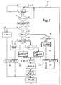
- Figure 2 shows how the flow diagram 1 can be modified to provide more useful information in the form of error decisions.
- the same reference numerals as before are used in Figure 2 for corresponding steps of the decision flow diagram 20.
- decision points 21,22,23,24 (or optionally those numbered 21,22,25) have been introduced that generate as outputs a value E d , that is either zero if no errors have been detected, or one, if there has been a detected error.
- Two other decision points 23 and 24 are on the paths in the flow diagram leading from the tests in steps 8 and 15 that found respectively either a CRC error or an unspecified sequence error in the present data cell.
- Figure 3 shows a disruption measurement flow diagram 30 that uses the error decision outputs E d from the decision flow diagram of Figure 2.
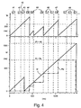
- Figures 4 and 5 show the results of the disruption measurement for two simplified example streams of cell data 40,50, each of which contains a header 60 with a sequence number followed by data 61. Data cells for which the sequence number is as expected, and the data is error-free are marked by ticks, and data cells that have an unexpected sequence number or erroneous data are marked by crosses.
- the first step in the disruption measurement flow diagram 30 is an initialisation step 31 in which certain values are initialised to zero, namely, a provisional disruption time value R p , the decision value E d , an error flag value E f , a time value output from a guard timer t g , and a time value output from a disruption timer t d .
- the guard timer value t g and disruption timer value t d are then set to run, while the disruption measurement flow diagram 30 awaits in step 32 an error decision point 21-25 to be reached in the decision flow diagram 20.
- first data cell 41,51 is correct, and in Figure 4 this is followed by two other correct data cells 42,43, before a first errored data cell 44.
- Figure 5 there is just one correct data cell 51, followed after an extended interval 54 by an errored data cell 52.
- the first errored data cell is followed by alternating correct and errored data cells, ending with a continuous stream of correct data cells 49,59.
- a test 34 is made as to whether or not the error flag value E f is zero.
- error flag is always zero, whether or not the first data cell 41,51 is correct, and so the path branches to test in step 34 whether or not the guard time value tg is greater than a predetermined guard time t i AND the error decision value E d is zero (i.e. no error).
- the path then loops back to step 32 awaiting the next decision.
- both the guard timer value tg and disruption timer value t d each continue to advance.
- the test 38 will branch to a step 39, in which the guard timer is reset and the provisional disruption time value R p is loaded with the current disruption time t d , and on other passes in which no error is detected, the test 38 branches to a step 45 in which a test is made as to whether or not the guard timer value t g has reached or exceeded the predetermined guard time t j . If the guard time value t g is less than the guard time t i , then the path loops back to await 32 the next error decision.
- the guard time t i is comparable to a few intervals between data cells, then it may be desired to load the output disruption time result R with the final disruption timer value t d . This would give a more conservative measure of the total disruption time. Either way, the duration of the service disruption event is determined from the disruption timer when the guard timer has timed the predetermined guard time.
- the arrangement of correct and errored data cells in Figure 5 is broadly similar to that of Figure 4. The difference is that the first correct data cell 51 is followed after an extended interval 54 by a first errored data cell 52.
- the result in the disruption measurement flow diagram 30 is that the disruption timer value t d is not reset in step 36 prior to the first errored cell 52. Therefore, the disruption timer value t d continues to increment even through the extended interval 54 is longer than the guard time t i . This however, gives a safe measure of the duration of a service disruption event, as in many cases it is likely that several data cells will be lost at the start of the disruption, for example when a data transmission fibre is cut.
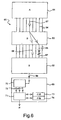
- FIG. 6 shows a simplified schematic diagram of apparatus 60 embodying the invention.
- An ATM network comprises a data source (A) 61 that is connected to a data receiver (B) 62 via a network switch (S) 63.
- a number of possible virtual channels 64,65 connect the switch to the data source 61 and data receiver 62.
- the data receiver 62 provides an output 66 of a particular data stream received from the source 61. If one of the virtual channels 67 carrying that particular data stream becomes cut or degraded, then protection switching will create a new virtual channel 68.
- a data analyzer 69 connected to the data output 66 can then be configured to perform the method of the invention.
- error detection means such as a microprocessor or application specific devices 70 can be programmed or configured to carry out the steps in the flow diagram of Figure 2 to generate error decision outputs 72.
- a separate or integral controlling processor 71 receiving the error decision can then perform the steps of the flow diagram of Figure 3.
- On-board or separate timers 73,74 can then be controlled by one of the processors 70,71 to produce the guard timer value t g and disruption timer t d value.
- the data analyzer 69 can generate a disruption time result R as described above.
- the invention therefore provides a convenient method and apparatus for measuring the duration of a service disruption event in an asynchronous transfer mode network.
Landscapes
- Engineering & Computer Science (AREA)
- Computer Networks & Wireless Communication (AREA)
- Data Exchanges In Wide-Area Networks (AREA)
- Time-Division Multiplex Systems (AREA)
Abstract
Description
- e) then using the guard timer to time a guard time interval when a subsequent data cell that is not corrupted is detected by the data analyzer whilst continuing to use the disruption timer to time the service disruption event; and then either
- f) resetting the guard timer if the data analyzer has detected a further corrupted data cell prior to the guard timer timing a predetermined guard time; or
- g) determining the duration of the service disruption event from the disruption timer when the guard timer has timed the predetermined guard time.
Claims (11)
- A method of measuring the duration of a service disruption event in an asynchronous transfer mode (ATM) data transmission channel, using a data analyzer that has both a disruption timer and a guard timer, the method comprising the steps of:characterised in that the method then comprises the steps of:a) providing an ATM stream of data into the data transmission channel, the data comprising a stream of identifiable data cells in a defined order;b) detecting with a data analyzer the stream of data after transmission through the data transmission channel in order to determine whether or not any of the data cells have been corrupted in transmission through the data transmission channel;c) disrupting the transmission of the stream of data through the data transmission channel so that at least some of the cells are corrupted;d) using the disruption timer to time the service disruption event when a first corrupted data cell is detected by the data analyzer;e) then using the guard timer to time a guard time interval when a subsequent data cell that is not corrupted is detected by the data analyzer whilst continuing to use the disruption timer to time the service disruption event; and then eitherf) resetting the guard timer if the data analyzer has detected a further corrupted data cell prior to the guard timer timing a predetermined guard time; org) determining the duration of the service disruption event from the disruption timer when the guard timer has timed the predetermined guard time.
- A method as claimed in Claim 1, in which in step e) said subsequent data cell is the second consecutive data cell that is not corrupted as detected by the data analyzer.
- A method as claimed in Claim 1 or 2, in which in step e) the guard time is timed starting from the detection of the last corrupted data cell.
- A method as claimed in any preceding claim, in which in step g) the duration of the service disruption event is a time measured from a start time prior to detection by the data analyzer of the first corrupted data cell until an end time at or following the consistent resumption of uncorrupted data cells.
- A method as claimed in Claim 4, in which the end time is at a time prior to the time at which the guard timer has reached a time at least as great as the guard time in step g).
- A method as claimed in Claim 4 or Claim 5, in which the start time is a time no later than the last uncorrupted data cell before the service disruption event.
- A method as claimed in Claim 6, in which the start time is a time which precedes said last uncorrupted data cell by no more than the guard time.
- A method as claimed in Claim 6, in which the start time is a time that may precede said last uncorrupted data cell by more than the guard time when there is a gap in the stream of data cells following the last uncorrupted data cell greater than the guard time.
- A method as claimed in any preceding claim, in which step b) is performed using the ITU-T Recommendation 0.191.
- A method as claimed in any preceding claim, in which the data analyzer characterises corrupted data cells according to whether cells have been errored, lost or misinserted.
- A data analyzer system for measuring the duration of a service disruption event in an asynchronous transfer mode (ATM) data transmission channel carrying an ATM stream of identifiable data cells in a defined order, the data analyzer system comprising error detection means for determining whether or not any of the data cells have been corrupted in transmission through the data transmission channel when the transmission is disrupted, and a disruption timer for timing the service disruption event starting when a first corrupted data cell is detected by the error detection means, characterised in that the data analyzer system has a guard timer for timing a guard time interval when uncorrupted data cells are detected by the error detection means, and control means for controlling the operation of the disruption timer and guard timer in response to the determination by the error detection means of whether or not any data cells have been corrupted, wherein the disruption timer is operable to time a service disruption event from the start of the disruption event until the guard timer has timed a predetermined guard time, and the guard timer is operable to time the guard time interval when corrupted data cells are followed by a resumption of uncorrupted data cells.
Applications Claiming Priority (2)
| Application Number | Priority Date | Filing Date | Title |
|---|---|---|---|
| GBGB9926884.9A GB9926884D0 (en) | 1999-11-12 | 1999-11-12 | ATM service disruption measurement |
| GB9926884 | 1999-11-12 |
Publications (3)
| Publication Number | Publication Date |
|---|---|
| EP1100234A2 true EP1100234A2 (en) | 2001-05-16 |
| EP1100234A3 EP1100234A3 (en) | 2003-06-11 |
| EP1100234B1 EP1100234B1 (en) | 2005-02-09 |
Family
ID=10864469
Family Applications (1)
| Application Number | Title | Priority Date | Filing Date |
|---|---|---|---|
| EP00309671A Expired - Lifetime EP1100234B1 (en) | 1999-11-12 | 2000-11-01 | ATM service disruption measurement |
Country Status (5)
| Country | Link |
|---|---|
| US (1) | US6765874B1 (en) |
| EP (1) | EP1100234B1 (en) |
| JP (1) | JP2001177541A (en) |
| DE (1) | DE60018016T2 (en) |
| GB (1) | GB9926884D0 (en) |
Cited By (2)
| Publication number | Priority date | Publication date | Assignee | Title |
|---|---|---|---|---|
| GB2406995A (en) * | 2003-09-16 | 2005-04-13 | Agilent Technologies Inc | Measuring service disruption |
| GB2410394A (en) * | 2004-01-22 | 2005-07-27 | Agilent Technologies Inc | Service disruption time determination in packet switched networks |
Families Citing this family (4)
| Publication number | Priority date | Publication date | Assignee | Title |
|---|---|---|---|---|
| US7002909B2 (en) * | 2001-07-25 | 2006-02-21 | Dorsal Networks, Inc. | Zero data loss network protection |
| US7362712B1 (en) * | 2003-12-29 | 2008-04-22 | At&T Corp. | SONET network outage impact measurement |
| US7899158B2 (en) * | 2006-08-22 | 2011-03-01 | Verizon Services Organization Inc. | Method and apparatus for measurement of service disruption interval |
| US12555001B2 (en) * | 2022-08-30 | 2026-02-17 | Ncr Atleos Corporation | Terminal power supply degradation detection |
Family Cites Families (12)
| Publication number | Priority date | Publication date | Assignee | Title |
|---|---|---|---|---|
| JP2999342B2 (en) * | 1993-03-19 | 2000-01-17 | 富士通株式会社 | Path route test method in ATM transmission system |
| JPH0897820A (en) * | 1994-09-29 | 1996-04-12 | Hitachi Ltd | UPC circuit and performance monitoring cell processing circuit |
| US5838924A (en) * | 1996-08-06 | 1998-11-17 | Lucent Technologies Inc | Asynchronous transfer mode (ATM) connection protection switching apparatus and method |
| CA2197263A1 (en) * | 1997-02-11 | 1998-08-11 | Dan Burke | Method of detecting signal degradation fault conditions within sonet and sdh signals |
| EP1010346B1 (en) * | 1997-08-22 | 2003-10-15 | Nortel Networks Limited | Protection switching trigger generation |
| JPH11145988A (en) * | 1997-11-11 | 1999-05-28 | Anritsu Corp | ATM line evaluation equipment |
| EP0917119A3 (en) * | 1997-11-12 | 2001-01-10 | Citicorp Development Center, Inc. | Distributed network based electronic wallet |
| EP0924891A1 (en) | 1997-12-15 | 1999-06-23 | Hewlett-Packard Company | Identification of framing symbols in a test signal |
| IT1297362B1 (en) * | 1997-12-31 | 1999-09-01 | Cit Alcatel | SYSTEM FOR DETECTION AND / OR MEASUREMENT OF THE DURATION OF MIXING IN TELECOMMUNICATIONS NETWORKS |
| JPH11225131A (en) * | 1998-02-04 | 1999-08-17 | Hitachi Commun Syst Inc | Errored seconds counting method for ATM transmission system |
| US6545976B1 (en) * | 1998-09-24 | 2003-04-08 | King Of Fans, Inc. | Measurement of network protection switch time |
| US6301254B1 (en) * | 1999-03-15 | 2001-10-09 | Tellabs Operations, Inc. | Virtual path ring protection method and apparatus |
-
1999
- 1999-11-12 GB GBGB9926884.9A patent/GB9926884D0/en not_active Ceased
-
2000
- 2000-11-01 DE DE60018016T patent/DE60018016T2/en not_active Expired - Fee Related
- 2000-11-01 EP EP00309671A patent/EP1100234B1/en not_active Expired - Lifetime
- 2000-11-13 JP JP2000345186A patent/JP2001177541A/en active Pending
- 2000-11-13 US US09/709,395 patent/US6765874B1/en not_active Expired - Lifetime
Cited By (4)
| Publication number | Priority date | Publication date | Assignee | Title |
|---|---|---|---|---|
| GB2406995A (en) * | 2003-09-16 | 2005-04-13 | Agilent Technologies Inc | Measuring service disruption |
| GB2406995B (en) * | 2003-09-16 | 2006-02-08 | Agilent Technologies Inc | Methods and apparatus for measuring service disruption |
| GB2410394A (en) * | 2004-01-22 | 2005-07-27 | Agilent Technologies Inc | Service disruption time determination in packet switched networks |
| GB2410394B (en) * | 2004-01-22 | 2007-04-04 | Agilent Technologies Inc | Service disruption time determination apparatus and method therefor |
Also Published As
| Publication number | Publication date |
|---|---|
| DE60018016T2 (en) | 2006-01-05 |
| GB9926884D0 (en) | 2000-01-12 |
| US6765874B1 (en) | 2004-07-20 |
| DE60018016D1 (en) | 2005-03-17 |
| EP1100234B1 (en) | 2005-02-09 |
| EP1100234A3 (en) | 2003-06-11 |
| JP2001177541A (en) | 2001-06-29 |
Similar Documents
| Publication | Publication Date | Title |
|---|---|---|
| US6154448A (en) | Next hop loopback | |
| US6654923B1 (en) | ATM group protection switching method and apparatus | |
| US6049530A (en) | Segment performance monitoring | |
| US6771908B2 (en) | Fast protection switching by snooping on downstream signals in an optical network | |
| US6778781B2 (en) | Health check algorithm for protection circuit in optical network | |
| EP0696111A2 (en) | A hitless path switching apparatus and method | |
| US6557112B1 (en) | QOS protection system | |
| US20030037297A1 (en) | Frame synchronization device and frame synchronization method | |
| US5440565A (en) | Test method and apparatus capable of testing reception of a desired cell through a virtual path | |
| US5627837A (en) | Apparatus and method for suppressing protection switching in a digital communication system in the event of an error burst | |
| EP1100234B1 (en) | ATM service disruption measurement | |
| US20050163053A1 (en) | Service disruption time determination apparatus and method therefor | |
| US6898177B1 (en) | ATM protection switching method and apparatus | |
| US6885632B1 (en) | Method and system for signal degrade (SD) information passthrough in T-Mux systems | |
| JPH04230143A (en) | Transmission quality evaluation apparatus | |
| US6545976B1 (en) | Measurement of network protection switch time | |
| JPH08181697A (en) | Uninterrupted transmission equipment | |
| KR100777874B1 (en) | How to Eliminate AP Receive Error in Optical Transmission System | |
| Matsunaga et al. | Virtual path test function and its mechanism for ATM transport networks | |
| JPH05344145A (en) | ATM test method | |
| JP2001308814A (en) | Frame configuration automatic identification communication device | |
| JPH05300171A (en) | Line quality measuring system for atm | |
| WO2000003558A1 (en) | Measurement of network protection switch time | |
| Kawase et al. | Hitless frame switching scheme for SDH networks | |
| JPH08307421A (en) | Continuity test method |
Legal Events
| Date | Code | Title | Description |
|---|---|---|---|
| PUAI | Public reference made under article 153(3) epc to a published international application that has entered the european phase |
Free format text: ORIGINAL CODE: 0009012 |
|
| AK | Designated contracting states |
Kind code of ref document: A2 Designated state(s): AT BE CH CY DE DK ES FI FR GB GR IE IT LI LU MC NL PT SE TR |
|
| AX | Request for extension of the european patent |
Free format text: AL;LT;LV;MK;RO;SI |
|
| RAP1 | Party data changed (applicant data changed or rights of an application transferred) |
Owner name: AGILENT TECHNOLOGIES INC. |
|
| RAP1 | Party data changed (applicant data changed or rights of an application transferred) |
Owner name: AGILENT TECHNOLOGIES INC. A DELAWARE CORPORATION |
|
| RAP1 | Party data changed (applicant data changed or rights of an application transferred) |
Owner name: AGILENT TECHNOLOGIES, INC. (A DELAWARE CORPORATION |
|
| PUAL | Search report despatched |
Free format text: ORIGINAL CODE: 0009013 |
|
| AK | Designated contracting states |
Designated state(s): AT BE CH CY DE DK ES FI FR GB GR IE IT LI LU MC NL PT SE TR |
|
| AX | Request for extension of the european patent |
Extension state: AL LT LV MK RO SI |
|
| 17P | Request for examination filed |
Effective date: 20031211 |
|
| AKX | Designation fees paid |
Designated state(s): DE FR GB |
|
| GRAP | Despatch of communication of intention to grant a patent |
Free format text: ORIGINAL CODE: EPIDOSNIGR1 |
|
| GRAS | Grant fee paid |
Free format text: ORIGINAL CODE: EPIDOSNIGR3 |
|
| GRAA | (expected) grant |
Free format text: ORIGINAL CODE: 0009210 |
|
| AK | Designated contracting states |
Kind code of ref document: B1 Designated state(s): DE FR GB |
|
| REG | Reference to a national code |
Ref country code: GB Ref legal event code: FG4D |
|
| REG | Reference to a national code |
Ref country code: IE Ref legal event code: FG4D |
|
| REF | Corresponds to: |
Ref document number: 60018016 Country of ref document: DE Date of ref document: 20050317 Kind code of ref document: P |
|
| PLBE | No opposition filed within time limit |
Free format text: ORIGINAL CODE: 0009261 |
|
| STAA | Information on the status of an ep patent application or granted ep patent |
Free format text: STATUS: NO OPPOSITION FILED WITHIN TIME LIMIT |
|
| ET | Fr: translation filed | ||
| 26N | No opposition filed |
Effective date: 20051110 |
|
| PGFP | Annual fee paid to national office [announced via postgrant information from national office to epo] |
Ref country code: FR Payment date: 20061117 Year of fee payment: 7 |
|
| PGFP | Annual fee paid to national office [announced via postgrant information from national office to epo] |
Ref country code: GB Payment date: 20061122 Year of fee payment: 7 |
|
| PGFP | Annual fee paid to national office [announced via postgrant information from national office to epo] |
Ref country code: DE Payment date: 20070102 Year of fee payment: 7 |
|
| GBPC | Gb: european patent ceased through non-payment of renewal fee |
Effective date: 20071101 |
|
| PG25 | Lapsed in a contracting state [announced via postgrant information from national office to epo] |
Ref country code: DE Free format text: LAPSE BECAUSE OF NON-PAYMENT OF DUE FEES Effective date: 20080603 |
|
| REG | Reference to a national code |
Ref country code: FR Ref legal event code: ST Effective date: 20080930 |
|
| PG25 | Lapsed in a contracting state [announced via postgrant information from national office to epo] |
Ref country code: GB Free format text: LAPSE BECAUSE OF NON-PAYMENT OF DUE FEES Effective date: 20071101 |
|
| PG25 | Lapsed in a contracting state [announced via postgrant information from national office to epo] |
Ref country code: FR Free format text: LAPSE BECAUSE OF NON-PAYMENT OF DUE FEES Effective date: 20071130 |