EP1100188A2 - Electric machine with permanent magnet poles and controllable rotor flux - Google Patents
Electric machine with permanent magnet poles and controllable rotor flux Download PDFInfo
- Publication number
- EP1100188A2 EP1100188A2 EP00309310A EP00309310A EP1100188A2 EP 1100188 A2 EP1100188 A2 EP 1100188A2 EP 00309310 A EP00309310 A EP 00309310A EP 00309310 A EP00309310 A EP 00309310A EP 1100188 A2 EP1100188 A2 EP 1100188A2
- Authority
- EP
- European Patent Office
- Prior art keywords
- rotor
- electric machine
- housing
- selectively
- magnetic flux
- Prior art date
- Legal status (The legal status is an assumption and is not a legal conclusion. Google has not performed a legal analysis and makes no representation as to the accuracy of the status listed.)
- Withdrawn
Links
- 230000004907 flux Effects 0.000 title claims description 29
- 230000005294 ferromagnetic effect Effects 0.000 claims abstract description 10
- 230000000712 assembly Effects 0.000 claims abstract description 7
- 238000000429 assembly Methods 0.000 claims abstract description 7
- 230000005291 magnetic effect Effects 0.000 claims description 28
- 238000004804 winding Methods 0.000 claims description 26
- 238000000034 method Methods 0.000 claims description 4
- 239000011810 insulating material Substances 0.000 claims description 2
- XEEYBQQBJWHFJM-UHFFFAOYSA-N Iron Chemical compound [Fe] XEEYBQQBJWHFJM-UHFFFAOYSA-N 0.000 description 8
- 230000001965 increasing effect Effects 0.000 description 4
- 229910052742 iron Inorganic materials 0.000 description 4
- 239000000696 magnetic material Substances 0.000 description 4
- 238000005520 cutting process Methods 0.000 description 3
- 229910000831 Steel Inorganic materials 0.000 description 2
- 230000008878 coupling Effects 0.000 description 2
- 238000010168 coupling process Methods 0.000 description 2
- 238000005859 coupling reaction Methods 0.000 description 2
- 239000003302 ferromagnetic material Substances 0.000 description 2
- 239000000463 material Substances 0.000 description 2
- 239000007858 starting material Substances 0.000 description 2
- 239000010959 steel Substances 0.000 description 2
- 230000015572 biosynthetic process Effects 0.000 description 1
- 230000001419 dependent effect Effects 0.000 description 1
- 230000003292 diminished effect Effects 0.000 description 1
- 230000005684 electric field Effects 0.000 description 1
- 230000001939 inductive effect Effects 0.000 description 1
- 238000012358 sourcing Methods 0.000 description 1
- 238000005728 strengthening Methods 0.000 description 1
- 230000003313 weakening effect Effects 0.000 description 1
Images

Classifications
-
- H—ELECTRICITY
- H02—GENERATION; CONVERSION OR DISTRIBUTION OF ELECTRIC POWER
- H02K—DYNAMO-ELECTRIC MACHINES
- H02K21/00—Synchronous motors having permanent magnets; Synchronous generators having permanent magnets
- H02K21/12—Synchronous motors having permanent magnets; Synchronous generators having permanent magnets with stationary armatures and rotating magnets
- H02K21/24—Synchronous motors having permanent magnets; Synchronous generators having permanent magnets with stationary armatures and rotating magnets with magnets axially facing the armatures, e.g. hub-type cycle dynamos
-
- H—ELECTRICITY
- H02—GENERATION; CONVERSION OR DISTRIBUTION OF ELECTRIC POWER
- H02K—DYNAMO-ELECTRIC MACHINES
- H02K1/00—Details of the magnetic circuit
- H02K1/06—Details of the magnetic circuit characterised by the shape, form or construction
- H02K1/22—Rotating parts of the magnetic circuit
- H02K1/27—Rotor cores with permanent magnets
- H02K1/2793—Rotors axially facing stators
- H02K1/2795—Rotors axially facing stators the rotor consisting of two or more circumferentially positioned magnets
- H02K1/2796—Rotors axially facing stators the rotor consisting of two or more circumferentially positioned magnets where both axial sides of the rotor face a stator
Definitions
- This invention relates to an electric machine, and more particularly, to a hybrid electric machine which generates flux by way of a plurality of permanent magnet poles, a plurality of consequent poles, and a selectively controllable field current, and which provides a relatively constant output power or voltage over a relatively wide range of operating speeds.
- Electric machines such as generators and motors generally utilise a plurality of rotating magnets and/or rotating magnetic members in order to generate electrical power and/or torque.
- One common type of electric machine known as an electromagnetic motor or generator, generally includes a rotor having a plurality of pole fingers in the form of north and south ferromagnetic members or consequent poles and one or more electric "field coils" which are selectively and electrically energised, thereby selectively producing a flux within the rotating members or "poles" of the rotor.
- electric power is supplied to the rotating field coils by way of one or more brushes, slip rings, and/or other devices.
- the output of these electromagnetic machines e.g., the output torque, power, and/or voltage
- these types of electric machines provide a relatively consistent output voltage, torque, or power over a relatively wide range of operating speeds and temperatures. While these electromagnetic machines are effective to generate a relatively consistent output voltage, torque, or power, they suffer from some drawbacks.
- the brushes, slip rings, and/or other devices which are required within these machines to provide an electrical connection to the rotating field coils, undesirably add to the cost, complexity, and size of the machines, and undesirably "wear” or degrade over time, thereby resulting in diminished performance and/or failure of the machine.
- a second type of electric machine known as a permanent magnet motor or generator, generally includes a rotor having a plurality of permanent magnets which form or create poles and selectively produce a flux within the machine. Due to the presence of permanent magnets within the rotor, these types of machines do not typically require field coils to produce magnetic flux. Therefore, these systems do not require the brushes, slip rings or other devices which are necessary in the previously described electromagnetic machines. As such, these permanent magnet machines are typically smaller, less complex, more efficient, and less costly than the previously described electromagnetic machines. These permanent magnet type machines do, however, suffer from some other drawbacks.
- the flux generated within these electric machines is provided by permanent magnets, the flux remains substantially constant and is relatively difficult to substantially alter or vary by the use of electric field coils.
- the output of these machines e.g., the output power or voltage
- these machines are only able provide a relatively consistent or constant output voltage, torque, or power over a relatively narrow and limited range of operating speeds. Therefore, these electric machines cannot be utilised in applications where the operating speed is provided by a relatively "variable" or fluctuating source, such as the engine of a vehicle.
- an electric machine includes a generally cylindrical ferromagnetic housing; first and second stator assemblies which are fixedly disposed within the housing and which each include a plurality of pole portions and a winding; a rotor which is rotatably disposed between the first and the second stator assemblies, the rotor having a plurality of permanent magnet poles which collectively generate a first magnetic flux and a plurality of consequent poles which co-operatively generate a second magnetic flux; and a coil which is fixedly coupled to the housing and is disposed in relative close proximity to the rotor. The coil is selectively energisable, and effective to controllably vary the second magnetic flux.
- a method for providing an electric machine having a controllable output voltage includes the steps of providing a ferromagnetic housing; providing a rotor having a plurality of permanent magnet poles which selectively generate a first magnetic flux and a plurality of consequent poles which selectively generate a second magnetic flux; disposing the rotor within the housing; providing a stator having winding; disposing the stator within the housing and in relative close proximity to the rotor; providing a field coil; fixedly disposing the field coil in relative close proximity to the rotor; selectively energising the winding effective to produce torque between the rotor and the stator, the torque having a magnitude; and selectively energising the field coil, effective to vary the second magnetic flux, thereby controlling the magnitude of the torque.
- the rotor includes poles generated from both permanent magnets and "soft" magnetic members.
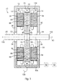
- assembly 10 includes a generally cylindrical housing or member 12, two substantially identical and opposed stator assemblies or members 14, 16 which are fixedly coupled to and/or are mounted within member 12, a generally disc-shaped rotor 18 which is disposed between and in relative close proximity to stator members 14 and 16 and which is coupled to a rotatable shaft 20, and a generally circular and stationary field coil 22, which is fixedly mounted within member 12.
- member 12 is formed and/or manufactured from a "soft" magnetic or ferromagnetic material such as iron.
- Member 12 includes a pair of substantially identical apertures 24, 26 which are respectively and integrally formed within sides 28, 30 of member 12.
- a pair of conventional bushing or bearing members 32, 34 are respectively and operatively housed within apertures 24, 26, and rotatably engage shaft 20, thereby allowing shaft 20 to rotate about the longitudinal axis 40 of shaft 20 while concomitantly and substantially maintaining the position of axis 40 within apertures 24, 26.
- Stator members 14, 16 are substantially identical in structure and function and are each respectively “ring” shaped.
- Members 14, 16 each include a centrally disposed aperture 44, a core portion 36, and a conventional stator coil or winding 38, which may comprise a conventional polyphase winding.
- winding 38 comprises three mutually independent windings which give rise to a conventional "three-phase" alternating current.
- cores 36 each respectively have four substantially identical raised or "pole” portions 46, which are separated by four substantially identical "channels” or recessed portions 48.
- stator members 14, 16 include a different number or quantity of raised portions 46 and a corresponding different number or quantity of channels or recessed portions 48.
- the number or quantity of raised portions 46 and recessed portions 48 are each equal to a multiple of three (3) .
- Winding 38 is wound around pole portions 46 in a conventional manner and is electrically, physically, and communicatively coupled to a switching and/or controller assembly 52 which may include a microprocessor/controller and a plurality of electrical and/or electromechanical switching and frequency converting components or devices, such as and without limitation transistors, diodes, relays, transformers, and other electrical components.
- Controller assembly 52 is electrically coupled to a conventional power supply or battery 53.
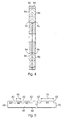
- stator cores 36 are each respectively manufactured from an amount or quantity of magnetic tape or "band” material 58, such as steel tape which is spirally wound or “coiled” from an initial or interior radius 54 to an exterior radius 56, as illustrated in Figure 1.
- Member 58 is preferably made of a soft magnetic material and is coated with a relatively thin layer of insulating material 60, which in one non-limiting embodiment comprises an oxide or an organic film.
- Member 58 includes a plurality of substantially identical recessed portions or "notches” 62, which collectively and cooperatively create and/or form channels 48 when core 36 is wound. In the preferred embodiment of the invention, notches 62 are cut, punched, or otherwise machined into member 58 in a conventional manner.
- Each notch 62 is separated by a raised portion 64 having a length which varies over the length of member 58 from the "beginning" or “inner” end 68 of member 58 to the “terminating" or “outer” end 70 of member 58.
- Portions 64 collectively and cooperatively create and/or form raised portions when core 36 is wound.
- the length 66 of each raised portion 64 (e.g., the distance between notches 62) is increased by a predetermined distance or amount for each portion 64 beginning at point or end 68 of core 36/member 58 and continuing through to the point or end 70 of core 36/member 58.
- this length 66 is increased to compensate for the radius of the core 36 which increases during the formation of core 36, as the core 36 is spirally “wrapped” or coiled, thereby producing larger circumferences and circumferential segments.
- the length of raised portion 64 i.e., length 66 which is illustrated in Figure 5
- the length of raised portion 64 is approximately equal to the length of curved or circumferential segment 72, which is illustrated in Figure 2
- the length of raised portion 64 i.e., length 74 which is illustrated in Figure 5
- member 58 will substantially conform to the desired structure of core 36 which is illustrated in Figure 2 when it is spirally wound or "wrapped”.
- member 58 is "fed” through and/or placed within a conventional stamping or tooling machine, which operates under stored program control, and which stamps or cuts notches 62 into member 58.
- each notch 62 is cut or stamped after a certain length of member 58 is fed through the machine, the distance or length between each notch 62 is increased as previously described.
- the distance between each notch 62 is calculated by the machine or by the stored program using the values of the inner radius 54 of the core 36, the outer radius 56 of core 36, and the "thickness" of member 58.
- Rotor 18 is manufactured from a ferromagnetic or "soft" magnetic material, such as iron or steel, and includes two disk shaped pole pieces or “halves" 80, 82 which are joined together in a conventional manner and which are collectively and conventionally coupled to rotor shaft 20.
- Each pole piece 80, 82 respectively includes a plurality of peripherally disposed permanent magnets or magnet members 84, 86, and 88, 90, which are made from a permanent magnet material. While the non-limiting embodiment illustrated in Figures 3 and 4 employs four magnets (i.e., magnets 84 - 90), other alternate embodiments employ different numbers or quantities of magnets.
- magnets 84 - 90 are semi-circular or "wedge-shaped" and have a trapezoidal-shaped cross section, as best shown in Figures 1 and 4.
- the magnets 84 - 90 are inserted into slots 92 - 98 which are respectively and integrally formed within pole pieces 80 and 82, and which also have "trapezoidal" cross sections which co-operate with the trapezoidal shape of magnets 84 - 90 to abuttingly engage and secure magnets 84 - 90 within pole pieces 80, 82, thereby substantially preventing magnets 84 - 90 from moving or becoming dislodged during operation of assembly 10.
- Magnets 84, 86 are respectively and abuttingly engaged with magnets 88, 90 as shown in Figures 1 and 4, with the south poles of magnets 88, 90 respectively abutting the north poles of magnets 84, 86.
- Each pole piece 80, 82 further respectively includes a plurality of peripherally disposed soft magnetic or ferromagnetic magnetic portions or "consequent poles" 108, 110 and 112, 114, which are respectively disposed “between” magnet members 84, 86, and 88, 90, or in an "alternating" relationship with members 84, 86 and 88, 90.
- Portions 108 - 114 are made from a soft magnetic or ferromagnetic material such as iron, and are capable of being temporarily magnetised in the presence of a field current.
- Alternate embodiments or rotor 18 having different or additional numbers of permanent magnets will have a corresponding different or additional number of consequent poles disposed in an alternating relationship with the permanent magnets (e.g., "between” the permanent magnets).
- the number of permanent magnets and consequent poles and the "pole pitch” of the permanent magnets and consequent poles will respectively correspond with and/or substantially equal the number of raised or pole portions 48 within stator core 36 and the "pitch" of pole portions 48.
- the number or quantity of raised portions 48 within stator core 36 will preferably be equal to a multiple of the total number or quantity of permanent magnets and consequent poles used (e.g., a multiple of three for a three-phase winding), and the pitch of pole portions 48 will preferably be equal to a fraction of the pitch of the magnets and consequent poles used (e.g., one third for a three-phase winding).
- Shaft 20 is generally cylindrical and includes a pair of ends 100, 102 which allow rotor 18 to be operatively coupled to a pulley, drive belt, or other device (not shown), which provides torque to rotor 18 and/or which receives torque from rotor 18.
- Field coil 22 is generally circular in shape and is mounted on a bobbin 21 which is fixedly and circumferentially coupled to the interior surface 104 of member 12. Coil 22 is disposed between stators 14, 16, in relative close proximity to rotor 18, and substantially encircles rotor 18. Coil 22 is electrically, physically, and communicatively coupled to switching and/or controller assembly 52 which selectively and operatively sources or provides electrical power to coil 22, from power supply 53 in a conventional manner.
- assembly 10 is coupled by way of one or both of ends 100, 102 to a device (not shown) which provides and/or receives torque to/from shaft 20.
- assembly 10 can be used as a motor to provide torque and power to other devices or apparatuses through shaft 20.
- controller 52 selectively sources or provides power from supply or battery 53 to field coil 22 and/or windings 38, thereby energising windings 38 and/or coil 22 effective to create a varying magnetic field or flux such as field 106, illustrated in Figure 1.
- the presence of the varying magnetic field or flux causes torque to develop between the rotor 18 and stators 14, 16, thereby causing rotor 18 to rotate about axis 40, and providing a rotational force or torque which is selectively transferable to other apparatuses or devices by way of shaft 20.
- field coil 22 is selectively activated by way of controller 52. Particularly, if the rotational speed of rotor 18 is less than or greater than the speed required to achieve a desired torque or power, controller 52 selectively activates and/or energises field coil 22. For example and without limitation, in order to increase the generated output torque or power, controller 52 sources power from battery 53 to field coil 22, thereby generating a field current within coil 22 in the direction of arrow 108.
- the generated field current causes the "soft" magnetic portions or sections 108 - 114 to act as poles which strengthen the overall flux magnitude of field 106.
- controller 52 selectively causes sections 108 - 114 to selectively provide the necessary additional flux needed to maintain a substantially consistent output torque or power.
- controller 52 selectively and controllably sources electrical power through coil 22 in the direction opposite arrow 108 (e.g., provides an inverted voltage), thereby causing sections 108 - 114 to act as poles which diminish or "weaken" the strength and/or magnitude of field 106 (e.g., causing sections 108 - 114 to generate a magnetic field/flux in the opposite direction as field 106), thereby reducing the overall torque and/or power provided by assembly 10.
- Assembly 10 may also be used as a "generator” or an “alternator” by coupling shaft 20 to a torque providing apparatus, such as a vehicle engine (not shown), by way of one or more pulleys, gears and/or other devices.
- a torque providing apparatus such as a vehicle engine (not shown)
- rotor 18 begins to rotate about axis 40.
- a varying magnetic field or flux such as field 106, is generated which passes through windings 38, thereby inducing a voltage and/or current within windings 38.
- field coil 22 is selectively activated by way of controller 52. Particularly, if the rotational speed of rotor 18 is less than or greater than the speed required to achieve a desired voltage, controller 52 selectively activates and/or energises field coil 22, as previously described. By varying the direction and/or magnitude of the field current within coil 22, controller 52 selectively causes sections 108 - 114 to selectively provide the necessary field "weakening" or “strengthening" flux needed or required to maintain a substantially consistent output voltage/current.
- assembly 10 selectively and controllably provides and maintains a substantially consistent output torque, power, and/or voltage over a relatively wide range of operational or rotational speeds.
- Assembly 10 provides this consistent output torque, power, and/or voltage over a relatively wide range of speeds without the use of brushes or slip rings, and with all of the other advantages associated with permanent magnet machines, such as a compact design and a relatively high efficiency.
- shaft 20 is coupled to the crankshaft of a vehicle engine and is used as both a motor (e.g., a "starter”) and an alternator, or a "starter-alternator”.
- assembly 10 may controllably and selectively cause the vehicle's engine to crank, thereby obviating the need for a separate vehicle starter.
- controller 52 can be used to selectively source power from battery 53 to coil 22 and/or windings 38, thereby providing a rotational torque through shaft 20 for turning/cranking the vehicle's engine.
- the coupling of the crankshaft of the vehicle's engine to shaft 20 provides the input torque and operating speed required to generate electrical power within assembly 10 as described above.
Landscapes
- Engineering & Computer Science (AREA)
- Power Engineering (AREA)
- Permanent Magnet Type Synchronous Machine (AREA)
- Dynamo-Electric Clutches, Dynamo-Electric Brakes (AREA)
Abstract
Description
Claims (10)
- An electric machine comprising:a generally cylindrical ferromagnetic housing (12);first and second stator assemblies (14,16) which are fixedly disposed within said housing (12) and which each include a plurality of pole portions (46) and a winding (38) ;a rotor (18) which is rotatably disposed between said first and said second stator assemblies (14,16), said rotor (18) having a plurality of permanent magnets (84,86,88,90) which collectively generate a first magnetic flux and a plurality of consequent poles which collectively generate a second magnetic flux; anda selectively energisable coil (22) fixedly coupled to said housing (12) and disposed in relative close proximity to said rotor (18), said selective energisation of said coil (22) being effective to controllably vary said second magnetic flux.
- An electric machine as claimed in claim 1 further including a controller which is operatively coupled to said coil and which is effective to cause said coil to become energised.
- An electric machine as claimed in claim 1 or claim 2, wherein said winding of said first stator and said winding of said second stator assembly each comprises a three-phase winding.
- An electric machine as claimed in any one of claims 1 to 3, wherein said first and second stator assemblies are each manufactured from a certain amount of spirally coiled ferromagnetic tape.
- An electric machine as claimed in claim 4, wherein said ferromagnetic tape is laminated with an insulating material.
- An electric machine as claimed in any one of the preceding claims, wherein each of said first and said second stator assembly each includes a plurality of channels wherein a portion of said winding is operatively disposed.
- An electric machine as claimed in any one of the preceding claims, wherein said rotor further comprises a plurality of slots in which said plurality permanent magnets is disposed.
- An electric machine as claimed in claim 7, wherein each of said plurality of magnets has a generally trapezoidal cross section which co-operates with said slots to secure each of said plurality of magnets within said rotor.
- An electric machine comprising:a housing;a pair of stators which are fixedly disposed within said housing and which each include a core and a winding;a first rotor which is rotatably mounted to a shaft and which is disposed between said pair of stators, said rotor having a first plurality of permanent magnets, a first plurality of consequent poles, a second plurality of permanent magnets which co-operate with said first plurality of permanent magnets to selectively generate a first magnetic flux, and a second plurality of consequent poles which co-operate with said first plurality of consequent poles to selectively generate a second magnetic flux; anda field coil, said field coil being fixedly and circumferentially mounted within said housing; anda controller which is operatively coupled to said field coil and which selectively provides power to said field coil, thereby causing said field coil to selectively vary said second magnetic flux.
- A method for providing an electric machine having a controllable output voltage, said method comprising the steps of:providing a ferromagnetic housing;providing a rotor having a plurality of permanent magnet poles which selectively generate a first magnetic flux and a plurality of consequent poles which selectively generate a second magnetic flux;disposing said rotor within said housing;providing a stator having winding;disposing said stator within said housing and in relative close proximity to said rotor;providing a field coil;fixedly disposing said field coil in relative close proximity to said rotor;selectively energising said winding effective to produce torque between said rotor and said stator, said torque having a magnitude; andselectively energising said field coil, effective to vary said second magnetic flux, thereby controlling said magnitude of said torque.
Applications Claiming Priority (2)
| Application Number | Priority Date | Filing Date | Title |
|---|---|---|---|
| US09/438,744 US6373162B1 (en) | 1999-11-11 | 1999-11-11 | Permanent magnet electric machine with flux control |
| US438744 | 1999-11-11 |
Publications (2)
| Publication Number | Publication Date |
|---|---|
| EP1100188A2 true EP1100188A2 (en) | 2001-05-16 |
| EP1100188A3 EP1100188A3 (en) | 2003-09-17 |
Family
ID=23741839
Family Applications (1)
| Application Number | Title | Priority Date | Filing Date |
|---|---|---|---|
| EP00309310A Withdrawn EP1100188A3 (en) | 1999-11-11 | 2000-10-23 | Electric machine with permanent magnet poles and controllable rotor flux |
Country Status (2)
| Country | Link |
|---|---|
| US (1) | US6373162B1 (en) |
| EP (1) | EP1100188A3 (en) |
Cited By (5)
| Publication number | Priority date | Publication date | Assignee | Title |
|---|---|---|---|---|
| EP1501174A4 (en) * | 2002-05-01 | 2005-10-05 | Makoto Ogoshi | Power generator and torque amplifier |
| WO2010037647A1 (en) * | 2008-10-01 | 2010-04-08 | Universität Bremen | Device for simulating the force effect of one or more mechanical drive elements on at least one drive component of a drive train |
| WO2015193562A1 (en) * | 2014-06-20 | 2015-12-23 | Whylot Sas | Electromagnetic synchronous motor with combined axial and radial magnetic fluxes |
| WO2015193563A1 (en) | 2014-06-20 | 2015-12-23 | Whylot Sas | Electromagnetic synchronous motor with combined axial and radial magnetic fluxes with double excitation |
| RU176105U1 (en) * | 2017-05-22 | 2018-01-09 | Закрытое Акционерное Общество "Научно-Исследовательский Институт Механотронных Технологий - Альфа - Научный Центр" | Non-contact dc motor |
Families Citing this family (93)
| Publication number | Priority date | Publication date | Assignee | Title |
|---|---|---|---|---|
| JP4061835B2 (en) * | 2000-11-06 | 2008-03-19 | 株式会社日立製作所 | Electric motor |
| US6605883B2 (en) * | 2001-04-20 | 2003-08-12 | Japan Servo Co., Ltd. | Multi-phase flat-type PM stepping motor and driving circuit thereof |
| US6740163B1 (en) * | 2001-06-15 | 2004-05-25 | Seagate Technology Llc | Photoresist recirculation and viscosity control for dip coating applications |
| DE10131428A1 (en) * | 2001-06-29 | 2003-01-16 | Bosch Gmbh Robert | Switched reluctance motor with radial and transverse flow |
| US6664689B2 (en) * | 2001-08-06 | 2003-12-16 | Mitchell Rose | Ring-shaped motor core with toroidally-wound coils |
| US6717324B2 (en) * | 2001-10-15 | 2004-04-06 | Ming Yan Chen | Magnet motor device |
| US6724110B2 (en) * | 2001-12-31 | 2004-04-20 | Visteon Global Technologies, Inc. | Reluctance generator for an eddy current braking system |
| JP3690355B2 (en) * | 2002-02-12 | 2005-08-31 | 日産自動車株式会社 | Stator support structure for rotating electrical machines |
| US7105979B1 (en) * | 2002-07-08 | 2006-09-12 | Gabrys Christopher W | Compact heteropolar hybrid alternator-motor |
| WO2004027961A1 (en) * | 2002-09-18 | 2004-04-01 | Neg Micon Control Systems A/S | An electrical motor/generator having a number of stator pole cores being larger than a number of rotor pole shoes |
| US7268454B2 (en) * | 2003-01-17 | 2007-09-11 | Magnetic Torque International, Ltd. | Power generating systems |
| US7233088B2 (en) | 2003-01-17 | 2007-06-19 | Magnetic Torque International, Ltd. | Torque converter and system using the same |
| JP4305649B2 (en) * | 2003-02-26 | 2009-07-29 | 株式会社富士通ゼネラル | Axial gap type electric motor |
| US6920023B2 (en) * | 2003-03-21 | 2005-07-19 | Pratt & Whitney Canada Corp. | Current limiting means for a generator |
| US7119467B2 (en) | 2003-03-21 | 2006-10-10 | Pratt & Whitney Canada Corp. | Current limiting means for a generator |
| US6965183B2 (en) * | 2003-05-27 | 2005-11-15 | Pratt & Whitney Canada Corp. | Architecture for electric machine |
| US7262539B2 (en) * | 2004-11-26 | 2007-08-28 | Pratt & Whitney Canada Corp. | Saturation control of electric machine |
| US7583063B2 (en) | 2003-05-27 | 2009-09-01 | Pratt & Whitney Canada Corp. | Architecture for electric machine |
| US7545056B2 (en) * | 2003-05-27 | 2009-06-09 | Pratt & Whitney Canada Corp. | Saturation control of electric machine |
| US7253548B2 (en) | 2003-06-16 | 2007-08-07 | Pratt & Whitney Canada Corp. | Method and apparatus for controlling an electric machine |
| TW200506241A (en) * | 2003-08-08 | 2005-02-16 | Yong-Han Liu | Non-contact wheel-type transmitting device |
| JP4349089B2 (en) * | 2003-11-10 | 2009-10-21 | 株式会社エクォス・リサーチ | Axial gap rotating electric machine |
| JP2005151725A (en) * | 2003-11-17 | 2005-06-09 | Equos Research Co Ltd | Axial gap rotating electric machine |
| US7112907B2 (en) | 2003-12-12 | 2006-09-26 | Siemens Vdo Automotive Inc. | Flux modifier for a permanent magnet brush-type motor using wound field coils combined with permanent magnets |
| US7045983B2 (en) * | 2004-02-17 | 2006-05-16 | Ford Motor Company | System for controlling motor speed by altering magnetic field of the motor |
| US7086838B2 (en) * | 2004-02-17 | 2006-08-08 | Ford Motor Company | Fuel system with a field modification module for controlling fuel flow |
| JP2005245079A (en) * | 2004-02-25 | 2005-09-08 | Kohei Minato | Magnetism rotation-type motor-generator |
| US7187098B2 (en) * | 2004-03-03 | 2007-03-06 | Kabushikikaisha Equos Research | Axial gap rotating electrical machine |
| US7081696B2 (en) | 2004-08-12 | 2006-07-25 | Exro Technologies Inc. | Polyphasic multi-coil generator |
| US20060087187A1 (en) * | 2004-10-27 | 2006-04-27 | Magnetic Torque International, Ltd. | Multivariable generator and method of using the same |
| US7808142B2 (en) * | 2004-10-27 | 2010-10-05 | E3 Solutions, Llc | Multivariable generator and method of using the same |
| US7332881B2 (en) * | 2004-10-28 | 2008-02-19 | Textron Inc. | AC drive system for electrically operated vehicle |
| US20060111191A1 (en) * | 2004-11-19 | 2006-05-25 | Magnetic Torque International | Torque transfer system and method of using the same |
| JP4904736B2 (en) * | 2005-07-21 | 2012-03-28 | 日産自動車株式会社 | Rotating electric machine stator |
| JP4680708B2 (en) * | 2005-07-28 | 2011-05-11 | 住友電気工業株式会社 | Axial type motor |
| US7608965B2 (en) * | 2005-09-01 | 2009-10-27 | Wisconsin Alumni Research Foundation | Field controlled axial flux permanent magnet electrical machine |
| US7525230B1 (en) * | 2005-10-20 | 2009-04-28 | Revolution Electric Motor Company | Air core motor-generator |
| GB0526023D0 (en) * | 2005-12-21 | 2006-02-01 | Em Digital Ltd | Electromagnetic actuator |
| US7288923B1 (en) | 2006-04-21 | 2007-10-30 | Pratt & Whitney Canada Corp. | Voltage-limited electric machine |
| US7385328B2 (en) * | 2006-05-23 | 2008-06-10 | Reliance Electric Technologies, Llc | Cogging reduction in permanent magnet machines |
| US8030816B2 (en) * | 2006-06-06 | 2011-10-04 | Honda Motor Co., Ltd. | Motor and motor control device |
| CA2654462A1 (en) | 2006-06-08 | 2007-12-13 | Exro Technologies Inc. | Poly-phasic multi-coil generator |
| JP4169055B2 (en) * | 2006-07-14 | 2008-10-22 | ダイキン工業株式会社 | Rotating electric machine |
| US7557482B2 (en) * | 2006-07-31 | 2009-07-07 | Caterpillar Inc. | Axial-flux electric machine |
| JP4709711B2 (en) * | 2006-08-04 | 2011-06-22 | 本田技研工業株式会社 | Magnetic power transmission device |
| JP4576406B2 (en) * | 2006-08-09 | 2010-11-10 | 本田技研工業株式会社 | Electric motor |
| WO2008068977A1 (en) * | 2006-12-06 | 2008-06-12 | Honda Motor Co., Ltd. | Axial gap motor |
| US20080164106A1 (en) * | 2007-01-04 | 2008-07-10 | Textron Inc. | Electric Brake for Utility Vehicles |
| US7898135B2 (en) * | 2007-03-07 | 2011-03-01 | Qm Power, Inc. | Hybrid permanent magnet motor |
| JP2008271640A (en) * | 2007-04-17 | 2008-11-06 | Honda Motor Co Ltd | Axial gap type motor |
| US8598761B2 (en) | 2007-05-03 | 2013-12-03 | In Motion Technologies Pty., Ltd. | Rotor magnet positioning device |
| US7800276B2 (en) * | 2007-05-17 | 2010-09-21 | Kurz-Kasch, Inc. | Rotor assembly |
| JP4707696B2 (en) * | 2007-06-26 | 2011-06-22 | 本田技研工業株式会社 | Axial gap type motor |
| JP4961302B2 (en) * | 2007-08-29 | 2012-06-27 | 本田技研工業株式会社 | Axial gap type motor |
| JP4729551B2 (en) | 2007-10-04 | 2011-07-20 | 本田技研工業株式会社 | Axial gap type motor |
| US7977843B2 (en) * | 2007-10-04 | 2011-07-12 | Honda Motor Co., Ltd. | Axial gap type motor |
| US7926889B2 (en) * | 2007-10-29 | 2011-04-19 | Textron Innovations Inc. | Hill hold for an electric vehicle |
| GB0800225D0 (en) * | 2008-01-07 | 2008-02-13 | Evo Electric Ltd | A rotor for an electrical machine |
| US8049389B2 (en) * | 2008-06-02 | 2011-11-01 | Honda Motor Co., Ltd. | Axial gap motor |
| US7906883B2 (en) * | 2008-06-02 | 2011-03-15 | Honda Motor Co., Ltd. | Axial gap motor |
| JP4678549B2 (en) * | 2008-10-09 | 2011-04-27 | 本田技研工業株式会社 | Axial gap type motor |
| JP4403253B1 (en) * | 2009-01-14 | 2010-01-27 | 有限会社クラ技術研究所 | Magnetic flux amount variable axial gap rotating electrical machine system |
| US9287739B2 (en) * | 2009-07-30 | 2016-03-15 | Bison Gear & Engineering Corp. | Axial flux stator and method of manufacture thereof |
| TW201108564A (en) * | 2009-08-19 | 2011-03-01 | Wen-Hong Huang | Magnetic double electric motor |
| SG190413A1 (en) | 2010-12-08 | 2013-06-28 | Prototus Ltd | Electromagnetic generator and method of using same |
| US9461508B2 (en) | 2012-05-30 | 2016-10-04 | Prototus, Ltd. | Electromagnetic generator transformer |
| TWI483514B (en) * | 2012-11-09 | 2015-05-01 | Ind Tech Res Inst | Axial-flux halbach rotor |
| GB2520516B (en) * | 2013-11-21 | 2021-08-25 | Time To Act Ltd | Direct drive generator for renewable energy applications |
| JP6282479B2 (en) * | 2014-02-14 | 2018-02-21 | ダイキン工業株式会社 | Axial gap type motor |
| JP6260994B2 (en) * | 2014-02-14 | 2018-01-17 | ダイキン工業株式会社 | Axial gap type motor |
| JP6260995B2 (en) * | 2014-02-14 | 2018-01-17 | ダイキン工業株式会社 | Axial gap type motor |
| CN105610288B (en) * | 2016-01-26 | 2018-02-27 | 江苏大学 | A kind of permanent-magnet torque and reluctance torque divergence type motor and optimum efficiency control method |
| JP6700596B2 (en) * | 2016-06-21 | 2020-05-27 | 株式会社デンソー | Rotor for axial gap motor and axial gap motor |
| JP2020521418A (en) | 2017-05-23 | 2020-07-16 | ディーピーエム テクノロジーズ インク. | Variable coil connection system |
| JP6676014B2 (en) * | 2017-08-07 | 2020-04-08 | 三菱重工業株式会社 | Axial gap motor and rotor manufacturing method |
| WO2020047663A1 (en) | 2018-09-05 | 2020-03-12 | Dpm Technologies Inc. | Systems and methods for intelligent energy storage and provisioning using an energy storage control system |
| US11171526B2 (en) * | 2018-09-24 | 2021-11-09 | The Board Of Trustees Of The University Of Alabama | Energy efficient permanent magnet synchronous motor |
| US11264877B2 (en) * | 2018-10-02 | 2022-03-01 | The University Of Akron | Axial flux machine |
| US10848014B2 (en) | 2019-04-12 | 2020-11-24 | Jacobi Motors LLC | Variable-flux memory motor and methods of controlling a variable-flux motor |
| WO2020215154A1 (en) | 2019-04-23 | 2020-10-29 | Dpm Technologies Inc. | Fault tolerant rotating electric machine |
| KR102868717B1 (en) | 2019-09-05 | 2025-10-02 | 마툴 홀딩스, 인크. | Systems and methods for magnetic rotating coupling devices |
| CN110707845A (en) * | 2019-09-18 | 2020-01-17 | 广州通达汽车电气股份有限公司 | Rotor structure and motor |
| US11522436B2 (en) | 2019-10-15 | 2022-12-06 | Darrell Schmidt Enterprises, Inc. | Permanently magnetized enhanced generator |
| WO2021076428A1 (en) | 2019-10-15 | 2021-04-22 | Darrell Schmidt Enterprises, Inc. | Magnetic coupler |
| EP4049361B1 (en) | 2019-10-25 | 2026-05-13 | Jacobi Motors LLC. | Methods of modifying the magnetization state and controlling a variable-flux memory motor |
| CN111211630B (en) * | 2020-01-21 | 2021-02-19 | 杭州中豪电动科技有限公司 | Disk type motor rotor |
| US11936256B2 (en) | 2020-04-24 | 2024-03-19 | Jacobi Motors, Llc | Flux-mnemonic permanent magnet synchronous machine and magnetizing a flux-mnemonic permanent magnet synchronous machine |
| FR3110641B1 (en) * | 2020-05-19 | 2023-05-26 | Inst Nat Polytechnique Toulouse | Magnetic circuit for creating a magnetic field in a main annular channel for ionization and acceleration of a Hall effect plasma thruster. |
| WO2022232904A1 (en) | 2021-05-04 | 2022-11-10 | Exro Technologies Inc. | Battery control systems and methods |
| CN117337545A (en) | 2021-05-13 | 2024-01-02 | Exro技术公司 | Method and device for driving coils of polyphase motors |
| US12620920B2 (en) | 2022-10-26 | 2026-05-05 | Jacobi Motors, Llc | System and method for shifting operation modes of variable flux memory motors |
| US12558980B2 (en) | 2023-11-09 | 2026-02-24 | Jacobi Motors, Llc | Integrated variable flux memory motor charger |
| US12614998B2 (en) | 2024-03-04 | 2026-04-28 | Jacobi Motors, Llc | System for multi-variable flux memory motor configuration |
Family Cites Families (24)
| Publication number | Priority date | Publication date | Assignee | Title |
|---|---|---|---|---|
| US2356972A (en) * | 1941-03-14 | 1944-08-29 | Ford Motor Co | Electrical apparatus |
| FR1541654A (en) | 1967-02-08 | 1968-10-11 | Electromagnetic turbine motor drive with electronic control | |
| US4363988A (en) * | 1978-06-12 | 1982-12-14 | General Electric Company | Induction disk motor with metal tape components |
| US4207483A (en) * | 1978-09-01 | 1980-06-10 | Warner Electric Brake & Clutch Co. | Step motor with circumferential stators on opposite sides of disc-like rotor |
| SE431275B (en) | 1983-04-07 | 1984-01-23 | Vnii Elektromash | ELECTRICAL MACHINE |
| US4559461A (en) * | 1983-06-23 | 1985-12-17 | Jeco Company Limited | Stepping motor |
| US4747288A (en) | 1985-03-28 | 1988-05-31 | General Electric Company | Method of forming an edgewise wound core |
| JPS6260451A (en) * | 1985-09-06 | 1987-03-17 | Nissan Motor Co Ltd | Permanent-magnet field disk type synchronous machine |
| US4656379A (en) | 1985-12-18 | 1987-04-07 | The Garrett Corporation | Hybrid excited generator with flux control of consequent-pole rotor |
| JPS63268459A (en) | 1987-04-24 | 1988-11-07 | Hitachi Ltd | motor |
| US4845424A (en) * | 1987-11-16 | 1989-07-04 | Gamble John G | Rotary displacement motor |
| US4996457A (en) * | 1990-03-28 | 1991-02-26 | The United States Of America As Represented By The United States Department Of Energy | Ultra-high speed permanent magnet axial gap alternator with multiple stators |
| US5152141A (en) * | 1991-04-08 | 1992-10-06 | Avco Corporation | Management of electrically driven engine accessories |
| GB2255452A (en) * | 1991-05-01 | 1992-11-04 | Pal Adam | Electric machines with iron-cored disc armature |
| DE4205926A1 (en) * | 1992-02-26 | 1993-09-16 | Magnet Motor Gmbh | ELECTRIC PUMP |
| JPH06351206A (en) * | 1993-04-14 | 1994-12-22 | Meidensha Corp | Hybrid excitation-type permanent-magnet synchronous rotating machine |
| US6037696A (en) * | 1993-12-29 | 2000-03-14 | Samot Engineering (1992) Ltd. | Permanent magnet axial air gap electric machine |
| US5530307A (en) * | 1994-03-28 | 1996-06-25 | Emerson Electric Co. | Flux controlled permanent magnet dynamo-electric machine |
| JPH08331784A (en) * | 1995-03-24 | 1996-12-13 | Hitachi Metals Ltd | Permanent magnet field type rotary machine |
| JP3530911B2 (en) * | 1995-03-29 | 2004-05-24 | 正 深尾 | Variable speed generator motor |
| US5925965A (en) * | 1996-09-06 | 1999-07-20 | Emerson Electric Co. | Axial flux reluctance machine with two stators driving a rotor |
| US6133662A (en) * | 1996-09-13 | 2000-10-17 | Hitachi, Ltd. | Permanent magnet dynamoelectric rotating machine and electric vehicle equipped with the same |
| US5982070A (en) * | 1996-12-27 | 1999-11-09 | Light Engineering Corporation | Electric motor or generator having amorphous core pieces being individually accomodated in a dielectric housing |
| EP0990094A1 (en) * | 1998-04-20 | 2000-04-05 | Robert Bosch Gmbh | Starting and driving unit for an internal combustion engine of a motor vehicle |
-
1999
- 1999-11-11 US US09/438,744 patent/US6373162B1/en not_active Expired - Lifetime
-
2000
- 2000-10-23 EP EP00309310A patent/EP1100188A3/en not_active Withdrawn
Cited By (7)
| Publication number | Priority date | Publication date | Assignee | Title |
|---|---|---|---|---|
| EP1501174A4 (en) * | 2002-05-01 | 2005-10-05 | Makoto Ogoshi | Power generator and torque amplifier |
| WO2010037647A1 (en) * | 2008-10-01 | 2010-04-08 | Universität Bremen | Device for simulating the force effect of one or more mechanical drive elements on at least one drive component of a drive train |
| WO2015193562A1 (en) * | 2014-06-20 | 2015-12-23 | Whylot Sas | Electromagnetic synchronous motor with combined axial and radial magnetic fluxes |
| WO2015193563A1 (en) | 2014-06-20 | 2015-12-23 | Whylot Sas | Electromagnetic synchronous motor with combined axial and radial magnetic fluxes with double excitation |
| FR3022706A1 (en) * | 2014-06-20 | 2015-12-25 | Whylot | ELECTROMAGNETIC SYNCHRONOUS MOTOR WITH MAGNETIC FLOWS COMBINED AXIAL AND RADIAL. |
| FR3022707A1 (en) * | 2014-06-20 | 2015-12-25 | Whylot | ELECTROMAGNETIC SYNCHRONOUS MOTOR WITH MAGNETIC FLOWS COMBINED AXIAL AND RADIAL WITH DOUBLE EXCITATION. |
| RU176105U1 (en) * | 2017-05-22 | 2018-01-09 | Закрытое Акционерное Общество "Научно-Исследовательский Институт Механотронных Технологий - Альфа - Научный Центр" | Non-contact dc motor |
Also Published As
| Publication number | Publication date |
|---|---|
| US6373162B1 (en) | 2002-04-16 |
| EP1100188A3 (en) | 2003-09-17 |
Similar Documents
| Publication | Publication Date | Title |
|---|---|---|
| US6373162B1 (en) | Permanent magnet electric machine with flux control | |
| US6531799B1 (en) | Hybrid electric machine with two rotors, permanent magnet poles and controllable field current | |
| EP0289292B1 (en) | Variable reluctance motor | |
| US8847464B2 (en) | Electrical machine with improved stator flux pattern across a rotor that permits higher torque density | |
| US5130595A (en) | Multiple magnetic paths machine | |
| KR100595076B1 (en) | An electrical machine with dual excitation, especially a motor vehicle alternator | |
| US7701104B2 (en) | Double-excitation rotating electrical machine for adjustable defluxing | |
| US7973444B2 (en) | Electric machine and rotor for the same | |
| US8294321B2 (en) | Brushless machine having ferromagnetic side plates and side magnets | |
| US9935532B2 (en) | Double-rotor type electrical rotating machines | |
| JP6723490B1 (en) | Rotating machine rotor | |
| EP0261953A2 (en) | Full flux reversal variable reluctance machine | |
| CN110663158B (en) | Dual magnetic phase material ring for AC motor | |
| EP3001549B1 (en) | Rotating electric machine | |
| EP3410574B1 (en) | Hybrid synchronous machines | |
| KR20130089142A (en) | Rotating electric machine in particular for a motor vehicle starter | |
| EP3163726B1 (en) | Flux control of permanent magnet electric machine | |
| JP2003134762A (en) | Rotating electric machine | |
| EP1037365A1 (en) | Motor generator developing high torque | |
| US6388356B1 (en) | Methods and apparatus for controlling electromagnetic flux in dynamoelectric machines | |
| US3293469A (en) | Electrical alternator | |
| US7646130B2 (en) | Stator segment and method of assembly | |
| CN110417156B (en) | Rotary electric machine | |
| US10536045B2 (en) | Rotor for rotating electric machine | |
| CN110417187A (en) | Rotating electric machine |
Legal Events
| Date | Code | Title | Description |
|---|---|---|---|
| PUAI | Public reference made under article 153(3) epc to a published international application that has entered the european phase |
Free format text: ORIGINAL CODE: 0009012 |
|
| AK | Designated contracting states |
Kind code of ref document: A2 Designated state(s): AT BE CH CY DE DK ES FI FR GB GR IE IT LI LU MC NL PT SE |
|
| AX | Request for extension of the european patent |
Free format text: AL;LT;LV;MK;RO;SI |
|
| PUAL | Search report despatched |
Free format text: ORIGINAL CODE: 0009013 |
|
| AK | Designated contracting states |
Kind code of ref document: A3 Designated state(s): AT BE CH CY DE DK ES FI FR GB GR IE IT LI LU MC NL PT SE |
|
| AX | Request for extension of the european patent |
Extension state: AL LT LV MK RO SI |
|
| RIC1 | Information provided on ipc code assigned before grant |
Ipc: 7H 02K 21/04 B Ipc: 7H 02K 21/14 A |
|
| 17P | Request for examination filed |
Effective date: 20040210 |
|
| 17Q | First examination report despatched |
Effective date: 20040423 |
|
| AKX | Designation fees paid |
Designated state(s): DE GB SE |
|
| 17Q | First examination report despatched |
Effective date: 20040423 |
|
| STAA | Information on the status of an ep patent application or granted ep patent |
Free format text: STATUS: THE APPLICATION IS DEEMED TO BE WITHDRAWN |
|
| 18D | Application deemed to be withdrawn |
Effective date: 20070110 |