EP1099989A2 - Hologram forming apparatus and method, and hologram - Google Patents
Hologram forming apparatus and method, and hologram Download PDFInfo
- Publication number
- EP1099989A2 EP1099989A2 EP00309878A EP00309878A EP1099989A2 EP 1099989 A2 EP1099989 A2 EP 1099989A2 EP 00309878 A EP00309878 A EP 00309878A EP 00309878 A EP00309878 A EP 00309878A EP 1099989 A2 EP1099989 A2 EP 1099989A2
- Authority
- EP
- European Patent Office
- Prior art keywords
- image
- train
- produced
- parallax
- hologram
- Prior art date
- Legal status (The legal status is an assumption and is not a legal conclusion. Google has not performed a legal analysis and makes no representation as to the accuracy of the status listed.)
- Withdrawn
Links
Images


Classifications
-
- G—PHYSICS
- G03—PHOTOGRAPHY; CINEMATOGRAPHY; ANALOGOUS TECHNIQUES USING WAVES OTHER THAN OPTICAL WAVES; ELECTROGRAPHY; HOLOGRAPHY
- G03H—HOLOGRAPHIC PROCESSES OR APPARATUS
- G03H1/00—Holographic processes or apparatus using light, infrared or ultraviolet waves for obtaining holograms or for obtaining an image from them; Details peculiar thereto
- G03H1/26—Processes or apparatus specially adapted to produce multiple sub- holograms or to obtain images from them, e.g. multicolour technique
- G03H1/30—Processes or apparatus specially adapted to produce multiple sub- holograms or to obtain images from them, e.g. multicolour technique discrete holograms only
-
- G—PHYSICS
- G03—PHOTOGRAPHY; CINEMATOGRAPHY; ANALOGOUS TECHNIQUES USING WAVES OTHER THAN OPTICAL WAVES; ELECTROGRAPHY; HOLOGRAPHY
- G03H—HOLOGRAPHIC PROCESSES OR APPARATUS
- G03H1/00—Holographic processes or apparatus using light, infrared or ultraviolet waves for obtaining holograms or for obtaining an image from them; Details peculiar thereto
- G03H1/02—Details of features involved during the holographic process; Replication of holograms without interference recording
-
- G—PHYSICS
- G03—PHOTOGRAPHY; CINEMATOGRAPHY; ANALOGOUS TECHNIQUES USING WAVES OTHER THAN OPTICAL WAVES; ELECTROGRAPHY; HOLOGRAPHY
- G03H—HOLOGRAPHIC PROCESSES OR APPARATUS
- G03H1/00—Holographic processes or apparatus using light, infrared or ultraviolet waves for obtaining holograms or for obtaining an image from them; Details peculiar thereto
- G03H1/26—Processes or apparatus specially adapted to produce multiple sub- holograms or to obtain images from them, e.g. multicolour technique
- G03H1/268—Holographic stereogram
-
- G—PHYSICS
- G03—PHOTOGRAPHY; CINEMATOGRAPHY; ANALOGOUS TECHNIQUES USING WAVES OTHER THAN OPTICAL WAVES; ELECTROGRAPHY; HOLOGRAPHY
- G03H—HOLOGRAPHIC PROCESSES OR APPARATUS
- G03H1/00—Holographic processes or apparatus using light, infrared or ultraviolet waves for obtaining holograms or for obtaining an image from them; Details peculiar thereto
- G03H1/02—Details of features involved during the holographic process; Replication of holograms without interference recording
- G03H2001/0204—Object characteristics
-
- G—PHYSICS
- G03—PHOTOGRAPHY; CINEMATOGRAPHY; ANALOGOUS TECHNIQUES USING WAVES OTHER THAN OPTICAL WAVES; ELECTROGRAPHY; HOLOGRAPHY
- G03H—HOLOGRAPHIC PROCESSES OR APPARATUS
- G03H2210/00—Object characteristics
- G03H2210/40—Synthetic representation, i.e. digital or optical object decomposition
- G03H2210/44—Digital representation
- G03H2210/441—Numerical processing applied to the object data other than numerical propagation
-
- G—PHYSICS
- G03—PHOTOGRAPHY; CINEMATOGRAPHY; ANALOGOUS TECHNIQUES USING WAVES OTHER THAN OPTICAL WAVES; ELECTROGRAPHY; HOLOGRAPHY
- G03H—HOLOGRAPHIC PROCESSES OR APPARATUS
- G03H2210/00—Object characteristics
- G03H2210/40—Synthetic representation, i.e. digital or optical object decomposition
- G03H2210/45—Representation of the decomposed object
- G03H2210/454—Representation of the decomposed object into planes
Definitions
- the present invention relates to a hologram forming apparatus and method. and also to a hologram formed by the apparatus and method.
- a holographic stereogram is produced by sequentially recording many images formed by sequentially photographing an object from different points of view, as rectangular or dot-like element holograms on a single hologram recording medium.
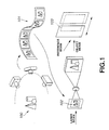
- FIG. 1 there is shown a conventional method for producing holographic stereogram.
- a holographic stereogram having parallax information only in the horizontal direction first an object 100 is photographed sequentially from different points of view to provide a sequence of parallax images 101 formed from a plurality of images having the parallax information in the horizontal direction. Then, images 102 in the sequence of parallax images 101 are sequentially recorded as rectangular element holograms in a hologram recording medium 103 so that the parallax images will be in succession in the horizontal direction.
- a holographic stereogram having the parallax information in the horizontal direction is provided.
- the information of the plurality of images 102 obtained by sequentially photographing the object from different horizontal points of view are sequentially recorded as rectangular element holograms so that they are in succession in the horizontal direction. So, when the holographic stereogram is viewed by the viewer with his or her both eyes, different two-dimensional images will be incident upon the right and left eyes, respectively. Thus, the viewer will feel a parallax and a three-dimensional image will be reconstructed from the different two-dimensional images. Namely, it has been proposed to record only a three-dimensional image in the hologram recording medium.
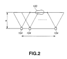
- the parallax image trains from which the holographic stereogram is produced can be formed by moving a camera 104 in parallel to an object 100 for example as shown in FIG. 2 with the camera 104 directed towards the object 100 and kept constantly so directed, thereby taking many pictures of the object 100 from different positions. More specifically, the camera 104 directed towards the object 100 is moved in parallel to the object 100 from a beginning position of a photographic range of the camera 104 to an end position where the object 100 is out of the photographic range, and thus, while moving the camera 104 kept constantly directed as in the above within the photographic range, many pictures of the object 100 are taken from different angles of viewing. Thus parallax images from which a holographic stereogram is produced can be obtained. Note that this method for taking many pictures of the object 100 from different positions by moving the camera 104 in parallel to the object 100 with the camera 104 kept constantly directed as in the above is called "straight track" system.
- original 3D image data are produced from pictures taken of an object using a special imaging method such as parallel or rotational movement of the camera.
- the original 3D image data can be produced by the computer graphics (CG).
- the present invention has an object to address the above-mentioned drawbacks of the prior art by providing a hologram forming apparatus and method, capable of holographically printing an image photographed using no special imaging method as a stereo image.
- the present invention has as another object to provide in at least preferred embodiments a holographic stereogram formed by artificially acquiring image information which would have to be in a great amount from a very small number of 2D image information.
- a hologram having recorded therein a parallax image train produced from an image synthesized by pasting a separately produced image on a stereo image model showing at least a part of a three-dimensional object previously prepared.
- a hologram having recorded therein a parallax image train produced from an image synthesized by pasting a train of separately produced images on a train of three-dimensional object images containing a stereo image model in at least a part thereof.
- the total construction of the holographic stereogram forming system will be described herebelow.
- a film-like hologram recording medium having recorded thereon an interference fringe resulted from an interference between object and reference beams is outputted directly as a holographic stereogram.
- the holographic stereogram having the fringe of interference between the object and reference beams recorded directly in the hologram recording medium is generally called "one-step holographic stereogram". That is, the holographic stereogram forming system which will be described in detail below is one example of the systems for forming such a one-step holographic stereogram.
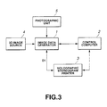
- the holographic stereogram forming system includes an image data generator 1 to produce data on images which are to be recorded in a holographic stereogram, a control computer 2 to control the entire system, and a holographic stereogram printer 3 having an optical system intended to form a holographic stereogram.
- the image data generator 1 produces data on a plurality of images corresponding to a plurality of element holograms which are to be recorded in a holographic stereogram (namely, data on parallax image train). Note that the production of image data by the image data generator 1 will further be described later. Briefly, separately captured images are combined with a stereo image model being at least a part of a three-dimensional object previously prepared to produce a synthetic image from which a parallax image train is produced. The three-dimensional object previously prepared and the stereo image model which is the part of the three-dimensional object are supplied from a 3D image source 4 to the image data generator 1. Also, the image data generator 1 is supplied with a two-dimensional image separately produced by a photographic unit 5 such as a digital camera or the like.
- a photographic unit 5 such as a digital camera or the like.
- the image data generator 1 When recording an image in a holograph recording medium, the image data generator 1 sends produced image data D1 for one image to the holographic stereogram printer 3 in an order of recording to the hologram recording medium, and sends to the control computer 2 a timing system indicating that the image data D 1 has been sent, each time the image data D 1 for one image is sent to the holographic stereogram printer 3.
- the control computer 2 drives the holographic stereogram printer 3 to sequentially record in a hologram recording medium set inside the holographic stereogram printer 3 an image based on the image data D 1 produced by the image data generator 1 as a rectangular element hologram.
- control computer 2 will control an exposure shutter and recording medium feeding mechanism provided in the holographic stereogram printer 3 as will further be described later. That is, the control computer 2 will send a control signal to the holographic stereogram printer 3 to control the opening and closing operation of the exposure shutter, hologram recording medium feeding operation of the recording medium feeding mechanism, etc.
- the holographic stereogram printer 3 prints element images on the hologram recording medium correspondingly to the parallax image train generated by the printing image processor 4.
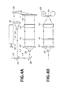
- the holographic stereogram printer 3 will be described in detail with reference to FIG. 4.
- FIG. 4A is top view of the entire optical system of the holographic stereogram printer 3
- FIG. 4B is a side elevation of a portion, for the object beam, of the optical system of the holographic stereogram printer 3.
- the holographic stereogram printer 3 includes a laser source 31 to emit a laser beam having a predetermined wavelength, an exposure shutter 32 and half mirror 33 disposed on the optical axis of a laser beam L1 from the laser source 31.
- the exposure shutter 32 is controlled by the control computer 2 to be closed for no exposure of the hologram recording medium 30 to the laser beam and opened for exposure of the hologram recording medium 30 to the laser beam.
- the half mirror 33 is provided to split a laser beam L2 having passed through the exposure shutter 32 into reference and object beams. A beam L3 reflected by the half mirror 33 is the reference beam, while a beam L4 having passed through the half mirror 33 is the object beam.
- a cylindrical lens 34 On the optical axis of the beam L3 reflected by the half mirror 33, there are disposed a cylindrical lens 34, collimator lens 35 to collimate the reference beam into a parallel beam, and a total reflection mirror 36 to reflect the parallel beam from the collimator lens 35, in this order.
- collimator lens 35 to collimate the reference beam into a parallel beam
- total reflection mirror 36 to reflect the parallel beam from the collimator lens 35, in this order.
- the beam reflected by the half mirror 33 is first diverged by the cylindrical lens 34, and then collimated into a parallel beam by the collimator lens 35. Thereafter, the parallel beam is reflected by the total reflection mirror 36 and incident upon the hologram recording medium 30.
- a total reflection mirror 38 to reflect the beam having passed through the half mirror 33
- spatial filter 39 being a combination of a convex lens and pinhole
- collimator lens 40 to collimator the object beam into a parallel beam
- display screen 41 on which an image to be recorded is displayed
- a cylindrical lens 42 to converge the object beam onto the hologram recording medium 30, in this order as shown in FIGS. 4A and 4B.
- the beam L4 having passed through the half mirror 33 is reflected by the total reflection mirror 38, then diverged by the spatial filter 39 (as a divergent beam from a point beam source), collimated into a parallel beam by the collimator lens 40 and then is incident upon the display screen 41.
- the display screen 41 is a transparent image display made of a liquid crystal for example, and displays thereon an image based on image data D1 sent from the printing image generator 1.
- the beam having passed through the display screen 41 is modulated correspondingly to the image displayed on the display screen 41, and then incident upon the cylindrical lens 42.
- the beam having passed through the display screen 41 is laterally focused by the cylindrical lens 42, and the focused beam is incident as an object beam upon the hologram recording medium 30.
- the projected beam from the display screen 41 is incident as a rectangular object beam upon the hologram recording medium 30.
- the reference beam is incident upon one of the main sides of the hologram recording medium 30 while the object beam is incident upon the other main side of the hologram recording medium 30. That is, the reference beam is incident at a predetermined angle of incidence upon one main side of the hologram recording medium 30, while the object beam is incident upon the hologram recording medium 30 so that its optical axis will be nearly perpendicular to the hologram recording medium 30.
- the reference beam and object beam will interfere with each other on the hologram recording medium 30, and an interference fringe generated by the interference is recorded as a change of the refractive index on the hologram recording medium 30.
- This holographic stereogram printer 3 for printing a holographic stereogram includes the recording medium feeding mechanism 43 which feeds the hologram recording medium 30 intermittently under the control of the control computer 2.
- the recording medium feeding mechanism 43 feeds the hologram recording medium 30 for one element hologram according to the control signal from the control computer 2.
- the images based on the image data D1 generated by the image data generator 1 are sequentially recorded on the hologram recording medium 30 to be horizontally contiguous to each other.
- the optical path of the reference beam reflected by the half mirror 33 and incident upon the hologram recording medium 30 should preferably be nearly equal in length to that of the object beam having passed through the half mirror 33 and incident upon the hologram recording medium 30 through the display screen 41.
- these optical paths are so equal to each other, the interference between the reference and object beams is increased, resulting in an improved quality of the holographic stereogram.
- the holographic stereogram printer 3 there may be disposed on the optical path of the object beam a dispersion plate to improve the quality of the holographic stereogram.
- the dispersion plate disposed on the optical path of the object beam disperses noise component included in the object beam for a more uniform intensity distribution of the object beam incident upon the hologram recording medium and an improved quality of a formed holographic stereogram.
- a mask having formed therein a rectangular opening corresponding to the shape of each element hologram. With such a mask, an excessive portion of the object beam dispersed by the dispersion plate will be intercepted by the mask. thereby permitting to form a higher-quality holographic stereogram.
- the holographic stereogram printer 3 there may be displayed on the optical path of the object beam a one-dimensional dispersion plate to disperse the longitudinal vertical angle of visibility. Owing to the one-dimensional dispersion plate disposed on the optical path of the object beam, the object beam will be dispersed longitudinally, namely, in the direction of the major axis of each formed element hologram. Thus, the formed holographic stereogram will have a longitudinal angle of visibility.
- the one-dimensional dispersion player when the one-dimensional dispersion player is disposed as in the above, there should preferably be disposed between the hologram recording medium 30 and one-dimensional dispersion plate a louver film having a fine blind-like grid. With the louver film disposed in this manner, it is possible to prevent the reference beam having passed through the hologram recording medium 30 from being reflected by the one-dimensional dispersion plate and being incident upon the hologram recording medium 30 again.
- the holographic stereogram forming system constructed as in the above functions as will be described below:
- the image data generator 1 When forming a holographic stereogram, the image data generator 1 sends image data D1 to the display screen 41 of the holographic stereogram printer 3 and allows the display screen 31 to display an exposure image based on the image data D1 thereon. At this time, the image data generator 1 sends to the control computer 2 a timing signal indicating that the image data D1 has been sent to the display screen 41 of the holographic stereogram printer 3.
- the control computer 2 Upon reception of the tuning signal, the control computer 2 sends a control signal to the exposure shutter 32 which will thus be opened for a predetermined time. Thus, the hologram recording medium 30 is exposed to the laser beam.
- the laser beam L3 reflected by the half mirror 33 is incident as a reference beam upon the hologram recording medium 30.
- the laser beam L4 having passed through the half mirror 33 has projected thereon the image displayed on the display screen 41, and incident as an object beam upon the hologram recording medium 30.
- the exposure image displayed on the display screen 41 is recorded as a rectangular element hologram on the hologram recording medium 30.
- control computer 2 When recording of one image on the hologram recording medium 30 is complete, the control computer 2 sends a control signal to the recording medium feeding mechanism 43 to feed the hologram recording medium 30 for one element hologram.
- exposure images displayed on the display screen 41 sequentially rearranged in the order of parallax images in train.
- exposure images based on the image data produced by the image data generator 1 are recorded as rectangular element holograms one after another on the hologram recording medium 30.
- the hologram recording medium 30 will oscillate somehow as the case may be when the hologram recording medium 30 is fed by the recording medium feeding mechanism 43. In such a case, each time the hologram recording medium 30 is fed, the element holograms are recorded after the oscillation is settled down.
- a plurality of exposure images based on image data produced by the image data generator 1 are sequentially displayed on the display screen 41, the exposure shutter 32 is opened for each of the exposure images, and then the exposure images are sequentially recorded as rectangular element holograms on the hologram recording medium 30.
- the hologram recording medium 30 is fed for one element hologram per image, the element holograms will be arranged horizontally in succession.
- a parallax image train consisting of a plurality of images including horizontal parallax information is recorded on the hologram recording medium 30 as a plurality of horizontal successive element holograms to provide a holographic stereogram having a horizontal parallax.
- the image data generator 1 combines a three-dimensional object image previously prepared by the 3D image source 4 and a two-dimensional image from the photographic unit 5 to produce a synthetic image, and produces from the synthetic image a parallax image train consisting of a plurality of images and from which a holographic stereogram is formed. As shown in FIG. 5, the image data generator 1 includes an image synthesizer 51 and parallax image train generator 52.
- the image synthesizer 51 is provided to combine a three-dimensional object image from the 3D image source 4 and a stereo image model being at least a part of the three-dimensional object image with a two-dimensional image picked up by the photographic unit 5.
- the parallax image train generator 52 is to produce a parallax image train by rendering a synthetic image from the image synthesizer 51.
- the 3D image source 4 has stored therein a 3D image acquired using the computer graphic (CG) or actual photography.
- the photographic unit 5 has stored in an internal recording medium thereof a two-dimensional image acquired by photography.
- a 3D image 55 from the 3D image source 4 and a two-dimensional image 57 from the photographic image 5 are combined by the image synthesizer 51.
- the 3D image 55 has formed therein a stereo image model 56 of a person having no eyebrows, eyes, nose, mouth, etc. and thus no expression in a face 56a being a three-dimensional polygon model.
- the two-dimensional image 57 is a human face having eyebrows, eyes, nose, mouth, etc. and thus an expression. This human face is combined with the face 56a being the three-dimensional polygon model.
- a synthetic image 58 is resulted from the combination of the two-dimensional image 57 with the three-dimensional polygon image 56a in the 3D image.
- the parallax image train generator 52 produces a parallax image train 59 consisting of images 59a, 59b and 59c by rendering and re-arranging, for hologram, the synthetic unage 58. Namely, the image data generator 1 combines the static 2D image with the 3D image, and totally renders the combined images to produce a parallax image train.
- the image data generator 1 constructed as shown in FIG. 5 can paste a separately captured still image on a stereo image model (e.g., polygon model) and combine a two-dimensional image and a three-dimensional image, thereby producing a parallax image train.
- a stereo image model e.g., polygon model
- the image data generator 1 can produce a parallax image train without using any special imaging method.
- the image data forming the a parallax image train is sequentially displayed on the display screen 41 of the holographic stereogram printer 3 as having been described above. Then, the exposure shutter 32 is opened for each image, and each of the images is sequentially recorded as a rectangular element hologram on the hologram recording medium 30.
- the image data generator 1 may be adapted to produce a train of images of a three-dimensional object previously prepared by the 3D image source 4 and a two-dimensional image train from the photographic unit 5 and combine these trains to produce a parallax image train.
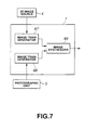
- the image data generator 1 includes an image train generator 67 for a 3D image, image train generator 68 for a still image, and an image synthesizer 69 as shown in FIG. 7.
- the image train generator 67 for a 3D image renders a three-dimensional object image from the 3D image source 4 and a 3D image consisting of a stereo image model being at least a part of the 3D object to produce a 3D image train.
- the image train generator 68 for a still image renders a two-dimensional image from the photographic unit 5 to produce a two-dimensional image train.
- the image synthesizer 69 combines the 3D image train from the image train generator 67 for a 3D image and a two-dimensional unage train from the image train generator 68 for a still image to produce a parallax image train.
- a 3D image 60 shows a background 61 including two trees and a stereo image model 62 of a person.
- the stereo image model 62 is a face 62a which is a three-dimensional polygon model having no eyebrows, eyes, nose, mouth, etc. and thus no expression.
- a two-dimensional image 64 is a human face having eyebrows, eyes, nose, mouth, etc. and thus an expression.
- the 3D image 60 from the 3D image source 4 is rendered by the 3D image train generator 67 to produce 3D images trains 63a. 63b and 63c.
- the two trees in the background 61 are changed by rendering to be backgrounds 61a, 61b and 61c.
- the two-dimensional image 64 from the photographic unit 5 is rendered by the two-dimensional image train generator 68 to produce two-dimensional image trains 65a, 65b and 65c whose face directions are different from each other.
- the image synthesizer 69 combines the 3D image trains 63a, 63b and 63c with the two-dimensional image trains 65a. 65b and 65c, respectively. By pasting the still image trains 65a, 65b and 65c on the face of the stereo image model 62. Thus, the image synthesizer 69 can produce parallax image trains 66a, 66b and 66c in which the background two trees and person's faces in one of the trains are different from those in the other trains.
- the image data generator 1 constructed as shown in FIG. 7 can also paste a separately captured image or the like on the stereo image model (polygon model or the like) and combines a two-dimensional image and a three-dimensional image to produce a parallax image train without using any special imaging method.
- the image data forming the parallax image trains are sequentially displayed on the display screen 41 of the holographic stereogram printer 3 as having been described above.
- the exposure shutter 32 is opened for each image, and the images are sequentially recorded as a rectangular element hologram on the hologram recording medium 30.
- the embodiment of the present invention can paste a normally captured two-dimensional image as a texture on a three-dimensional image model prepared in advance to provide a three-dimensional hologram print approximate to an actual view without using any special imaging method apparatus.
- 3D models of a Santa Claus's cap, mustache and beard, and clothing and also a background are prepared as CG data.
- a face portion is cut from a person's picture taken by a digital still camera for example, and pasted as a texture on the face portion of the Santa Claus in the 3D model image.
- the two-dimensional face image is synthesized on the three-dimensional polygon to produce a three-dimensional image of the Santa Claus. This is holographically printed to produce a three-dimensional unique Christmas card or the like for example.
- the parallax image train produced by the image data generator 1 may be supplied to the holographic stereogram printer 3 via a network such as the Internet, WAN, LAN, radio communications or the like, removable medium such as FD, MD, CD-R, memory card or the like, video tape, hard disc, etc.
- a network such as the Internet, WAN, LAN, radio communications or the like, removable medium such as FD, MD, CD-R, memory card or the like, video tape, hard disc, etc.
- holographic stereogram can only be produced from a large amount of image information. According to the present invention, however, it is possible to produce a holographic stereogram by artificially acquiring only a small amount of two-dimensional information. Thus. a holographic stereogram can be provided inexpensively.
Landscapes
- Physics & Mathematics (AREA)
- General Physics & Mathematics (AREA)
- Holo Graphy (AREA)
Abstract
The image data generator 1 produces image data for recording into a
holographic stereogram. The image data generator 1 combines a stereo image
model being at least a part of a three-dimensional object image prepared in advance
with a separately captured image to provide a synthetic image and produces a
parallax image train from the synthetic image. The three-dimensional object image
prepared in advance and stereo image model being the part of the three-dimensional
object are supplied from the 3D image source 4 to the image data
generator 1. The image data generator 1 is also supplied with a two-dimensional
image separately captured from the photographic unit 5 such as a digital still
camera for example.
Description
- The present invention relates to a hologram forming apparatus and method. and also to a hologram formed by the apparatus and method.
- A holographic stereogram is produced by sequentially recording many images formed by sequentially photographing an object from different points of view, as rectangular or dot-like element holograms on a single hologram recording medium.
- Referring now to FIG. 1, there is shown a conventional method for producing holographic stereogram. For example, to form a holographic stereogram having parallax information only in the horizontal direction, first an
object 100 is photographed sequentially from different points of view to provide a sequence ofparallax images 101 formed from a plurality of images having the parallax information in the horizontal direction. Then,images 102 in the sequence ofparallax images 101 are sequentially recorded as rectangular element holograms in ahologram recording medium 103 so that the parallax images will be in succession in the horizontal direction. Thus, a holographic stereogram having the parallax information in the horizontal direction is provided. - In the holographic stereogram, the information of the plurality of
images 102 obtained by sequentially photographing the object from different horizontal points of view are sequentially recorded as rectangular element holograms so that they are in succession in the horizontal direction. So, when the holographic stereogram is viewed by the viewer with his or her both eyes, different two-dimensional images will be incident upon the right and left eyes, respectively. Thus, the viewer will feel a parallax and a three-dimensional image will be reconstructed from the different two-dimensional images. Namely, it has been proposed to record only a three-dimensional image in the hologram recording medium. - The parallax image trains from which the holographic stereogram is produced can be formed by moving a
camera 104 in parallel to anobject 100 for example as shown in FIG. 2 with thecamera 104 directed towards theobject 100 and kept constantly so directed, thereby taking many pictures of theobject 100 from different positions. More specifically, thecamera 104 directed towards theobject 100 is moved in parallel to theobject 100 from a beginning position of a photographic range of thecamera 104 to an end position where theobject 100 is out of the photographic range, and thus, while moving thecamera 104 kept constantly directed as in the above within the photographic range, many pictures of theobject 100 are taken from different angles of viewing. Thus parallax images from which a holographic stereogram is produced can be obtained. Note that this method for taking many pictures of theobject 100 from different positions by moving thecamera 104 in parallel to theobject 100 with thecamera 104 kept constantly directed as in the above is called "straight track" system. - For 3D (three-dimensional) printing of the images in a hologram, original 3D image data are produced from pictures taken of an object using a special imaging method such as parallel or rotational movement of the camera. Also, the original 3D image data can be produced by the computer graphics (CG).
- As mentioned above, printing of a real-object image in a hologram needs to actually photograph the real object by a camera or the like. In this case, the special photography is necessary as in the above and to this end, a special equipment is also required. Conventionally, much labor, techniques and costs are needed for the photography.
- Accordingly, the present invention has an object to address the above-mentioned drawbacks of the prior art by providing a hologram forming apparatus and method, capable of holographically printing an image photographed using no special imaging method as a stereo image.
- The present invention has as another object to provide in at least preferred embodiments a holographic stereogram formed by artificially acquiring image information which would have to be in a great amount from a very small number of 2D image information.
- The above objects can be addressed by providing a hologram forming apparatus including according to the present invention:
- means for pasting a separately produced image on a stereo image model showing at least a part of a three-dimensional object previously prepared to produce a synthetic image; and
- means for producing parallax image train from the synthetic image from the image synthesizing means.
-
- Also the above objects can be addressed by providing a hologram forming method including, according to the present invention, steps of:
- pasting a separately produced image on a stereo image model showing at least a part of a three-dimensional object previously prepared to produce a synthetic image; and
- producing a parallax image train from the synthetic image produced at the synthesizing step.
-
- Also the above objects can be addressed by providing a hologram forming apparatus including according to the present invention:
- first means for producing a three-dimensional object image train containing a stereo image model in at least a part thereof;
- second means for producing a train of images produced separately; and
- means for pasting the image train produced by the second image train producing means on the stereo image model of the three-dimensional object image train produced by the first image train producing means to synthesize a parallax image train.
-
- Also the above objects can be addressed by providing a hologram forming method including, according to the present invention:
- a first step of producing a three-dimensional object image train containing a stereo image model in at least a part thereof;
- a second step of producing a train of images produced separately; and
- a step of pasting the image train produced at the second image train producing step on the stereo image model of the three-dimensional object image train produced at the second image train producing step to synthesize a parallax image train.
-
- Also the above objects can be addressed by providing a hologram having recorded therein a parallax image train produced from an image synthesized by pasting a separately produced image on a stereo image model showing at least a part of a three-dimensional object previously prepared.
- Also the above objects can be addressed by providing a hologram having recorded therein a parallax image train produced from an image synthesized by pasting a train of separately produced images on a train of three-dimensional object images containing a stereo image model in at least a part thereof.
- These objects and other objects, features and advantages of the present intention will become more apparent from the following detailed description of the preferred embodiments of the present invention when taken in conjunction with the accompanying drawings.
- Embodiments of the invention will now be described, by way of example only, with reference to the accompanying drawings in which:
- FIG. 1 explains the conventional method for producing holographic stereogram;
- FIG. 2 explains the straight track system;
- FIG. 3 is a block diagram of the holographic stereogram forming apparatus according to one example embodiment of the present invention;
- FIG. 4 shows the optical system of the holographic stereogram printer;
- FIG. 5 is a block diagram of the data generator forming the holographic stereogram forming apparatus;
- FIG. 6 explains a concrete example of the operations effected for production of a parallax image train by the data generator shown in FIG. 5;
- FIG. 7 is a block diagram of a variant of the data generator in FIG. 5; and
- FIG. 8 explains a concrete example of the operations effected for production of a parallax image train by the variant of the data generator in FIG. 7.
-
- First, the total construction of the holographic stereogram forming system will be described herebelow. Note that in the holographic stereogram forming system, a film-like hologram recording medium having recorded thereon an interference fringe resulted from an interference between object and reference beams is outputted directly as a holographic stereogram. The holographic stereogram having the fringe of interference between the object and reference beams recorded directly in the hologram recording medium is generally called "one-step holographic stereogram". That is, the holographic stereogram forming system which will be described in detail below is one example of the systems for forming such a one-step holographic stereogram.
- As shown in FIG. 3, the holographic stereogram forming system includes an
image data generator 1 to produce data on images which are to be recorded in a holographic stereogram, acontrol computer 2 to control the entire system, and aholographic stereogram printer 3 having an optical system intended to form a holographic stereogram. - The
image data generator 1 produces data on a plurality of images corresponding to a plurality of element holograms which are to be recorded in a holographic stereogram (namely, data on parallax image train). Note that the production of image data by theimage data generator 1 will further be described later. Briefly, separately captured images are combined with a stereo image model being at least a part of a three-dimensional object previously prepared to produce a synthetic image from which a parallax image train is produced. The three-dimensional object previously prepared and the stereo image model which is the part of the three-dimensional object are supplied from a3D image source 4 to theimage data generator 1. Also, theimage data generator 1 is supplied with a two-dimensional image separately produced by aphotographic unit 5 such as a digital camera or the like. - When recording an image in a holograph recording medium, the
image data generator 1 sends produced image data D1 for one image to theholographic stereogram printer 3 in an order of recording to the hologram recording medium, and sends to the control computer 2 a timing system indicating that theimage data D 1 has been sent, each time theimage data D 1 for one image is sent to theholographic stereogram printer 3. - According to the timing signal sent from the
image data generator 1. thecontrol computer 2 drives theholographic stereogram printer 3 to sequentially record in a hologram recording medium set inside theholographic stereogram printer 3 an image based on theimage data D 1 produced by theimage data generator 1 as a rectangular element hologram. - At this time, the
control computer 2 will control an exposure shutter and recording medium feeding mechanism provided in theholographic stereogram printer 3 as will further be described later. That is, thecontrol computer 2 will send a control signal to theholographic stereogram printer 3 to control the opening and closing operation of the exposure shutter, hologram recording medium feeding operation of the recording medium feeding mechanism, etc. - The
holographic stereogram printer 3 prints element images on the hologram recording medium correspondingly to the parallax image train generated by theprinting image processor 4. Theholographic stereogram printer 3 will be described in detail with reference to FIG. 4. FIG. 4A is top view of the entire optical system of theholographic stereogram printer 3, and FIG. 4B is a side elevation of a portion, for the object beam, of the optical system of theholographic stereogram printer 3. - As shown in FIG. 4A, the
holographic stereogram printer 3 includes alaser source 31 to emit a laser beam having a predetermined wavelength, anexposure shutter 32 andhalf mirror 33 disposed on the optical axis of a laser beam L1 from thelaser source 31. - The
exposure shutter 32 is controlled by thecontrol computer 2 to be closed for no exposure of thehologram recording medium 30 to the laser beam and opened for exposure of thehologram recording medium 30 to the laser beam. Thehalf mirror 33 is provided to split a laser beam L2 having passed through theexposure shutter 32 into reference and object beams. A beam L3 reflected by thehalf mirror 33 is the reference beam, while a beam L4 having passed through thehalf mirror 33 is the object beam. - On the optical axis of the beam L3 reflected by the
half mirror 33, there are disposed acylindrical lens 34,collimator lens 35 to collimate the reference beam into a parallel beam, and atotal reflection mirror 36 to reflect the parallel beam from thecollimator lens 35, in this order. These optical parts form together an optical system for the reference beam - The beam reflected by the
half mirror 33 is first diverged by thecylindrical lens 34, and then collimated into a parallel beam by thecollimator lens 35. Thereafter, the parallel beam is reflected by thetotal reflection mirror 36 and incident upon thehologram recording medium 30. - On the other hand, on the optical axis of the beam L4 having passed through the
half mirror 33, there are disposed atotal reflection mirror 38 to reflect the beam having passed through thehalf mirror 33,spatial filter 39 being a combination of a convex lens and pinhole,collimator lens 40 to collimator the object beam into a parallel beam,display screen 41 on which an image to be recorded is displayed, and acylindrical lens 42 to converge the object beam onto thehologram recording medium 30, in this order as shown in FIGS. 4A and 4B. These optical parts form together an optical system for the object beam. - The beam L4 having passed through the
half mirror 33 is reflected by thetotal reflection mirror 38, then diverged by the spatial filter 39 (as a divergent beam from a point beam source), collimated into a parallel beam by thecollimator lens 40 and then is incident upon thedisplay screen 41. Thedisplay screen 41 is a transparent image display made of a liquid crystal for example, and displays thereon an image based on image data D1 sent from theprinting image generator 1. The beam having passed through thedisplay screen 41 is modulated correspondingly to the image displayed on thedisplay screen 41, and then incident upon thecylindrical lens 42. - Then, the beam having passed through the
display screen 41 is laterally focused by thecylindrical lens 42, and the focused beam is incident as an object beam upon thehologram recording medium 30. Namely, at theholographic stereogram printer 3, the projected beam from thedisplay screen 41 is incident as a rectangular object beam upon thehologram recording medium 30. - Of the reference beam and object beam, the reference beam is incident upon one of the main sides of the
hologram recording medium 30 while the object beam is incident upon the other main side of thehologram recording medium 30. That is, the reference beam is incident at a predetermined angle of incidence upon one main side of thehologram recording medium 30, while the object beam is incident upon thehologram recording medium 30 so that its optical axis will be nearly perpendicular to thehologram recording medium 30. Thus, the reference beam and object beam will interfere with each other on thehologram recording medium 30, and an interference fringe generated by the interference is recorded as a change of the refractive index on thehologram recording medium 30. - This
holographic stereogram printer 3 for printing a holographic stereogram includes the recordingmedium feeding mechanism 43 which feeds thehologram recording medium 30 intermittently under the control of thecontrol computer 2. Each time one image based on the image data D1 produced by theimage data generator 1 is recorded as one element image on the hologram recording medium set in a predetermined condition in the recordingmedium feeding mechanism 43, the recordingmedium feeding mechanism 43 feeds thehologram recording medium 30 for one element hologram according to the control signal from thecontrol computer 2. Thus, the images based on the image data D1 generated by theimage data generator 1 are sequentially recorded on thehologram recording medium 30 to be horizontally contiguous to each other. - In the
holographic stereogram printer 3, the optical path of the reference beam reflected by thehalf mirror 33 and incident upon thehologram recording medium 30 should preferably be nearly equal in length to that of the object beam having passed through thehalf mirror 33 and incident upon thehologram recording medium 30 through thedisplay screen 41. When these optical paths are so equal to each other, the interference between the reference and object beams is increased, resulting in an improved quality of the holographic stereogram. - Also, in the
holographic stereogram printer 3, there may be disposed on the optical path of the object beam a dispersion plate to improve the quality of the holographic stereogram. The dispersion plate disposed on the optical path of the object beam disperses noise component included in the object beam for a more uniform intensity distribution of the object beam incident upon the hologram recording medium and an improved quality of a formed holographic stereogram. - When the dispersion plate is disposed, however, there should preferably be provided between the dispersion plate and hologram recording medium 30 a mask having formed therein a rectangular opening corresponding to the shape of each element hologram. With such a mask, an excessive portion of the object beam dispersed by the dispersion plate will be intercepted by the mask. thereby permitting to form a higher-quality holographic stereogram.
- Also in the
holographic stereogram printer 3, there may be displayed on the optical path of the object beam a one-dimensional dispersion plate to disperse the longitudinal vertical angle of visibility. Owing to the one-dimensional dispersion plate disposed on the optical path of the object beam, the object beam will be dispersed longitudinally, namely, in the direction of the major axis of each formed element hologram. Thus, the formed holographic stereogram will have a longitudinal angle of visibility. - However, when the one-dimensional dispersion player is disposed as in the above, there should preferably be disposed between the
hologram recording medium 30 and one-dimensional dispersion plate a louver film having a fine blind-like grid. With the louver film disposed in this manner, it is possible to prevent the reference beam having passed through thehologram recording medium 30 from being reflected by the one-dimensional dispersion plate and being incident upon thehologram recording medium 30 again. - The holographic stereogram forming system constructed as in the above functions as will be described below:
- When forming a holographic stereogram, the
image data generator 1 sends image data D1 to thedisplay screen 41 of theholographic stereogram printer 3 and allows thedisplay screen 31 to display an exposure image based on the image data D1 thereon. At this time, theimage data generator 1 sends to the control computer 2 a timing signal indicating that the image data D1 has been sent to thedisplay screen 41 of theholographic stereogram printer 3. - Upon reception of the tuning signal, the
control computer 2 sends a control signal to theexposure shutter 32 which will thus be opened for a predetermined time. Thus, thehologram recording medium 30 is exposed to the laser beam. - At this time, of the laser beam L2 having been emitted from the
laser source 31 and having passed through theexposure shutter 32, the laser beam L3 reflected by thehalf mirror 33 is incident as a reference beam upon thehologram recording medium 30. Also, the laser beam L4 having passed through thehalf mirror 33 has projected thereon the image displayed on thedisplay screen 41, and incident as an object beam upon thehologram recording medium 30. Thus, the exposure image displayed on thedisplay screen 41 is recorded as a rectangular element hologram on thehologram recording medium 30. - When recording of one image on the
hologram recording medium 30 is complete, thecontrol computer 2 sends a control signal to the recordingmedium feeding mechanism 43 to feed thehologram recording medium 30 for one element hologram. - The above operations are repeated with the exposure images displayed on the
display screen 41 sequentially rearranged in the order of parallax images in train. Thus, exposure images based on the image data produced by theimage data generator 1 are recorded as rectangular element holograms one after another on thehologram recording medium 30. - Note that during sequential recording of element holograms, the
hologram recording medium 30 will oscillate somehow as the case may be when thehologram recording medium 30 is fed by the recordingmedium feeding mechanism 43. In such a case, each time thehologram recording medium 30 is fed, the element holograms are recorded after the oscillation is settled down. - As in the above, in the holographic stereogram forming system, a plurality of exposure images based on image data produced by the
image data generator 1 are sequentially displayed on thedisplay screen 41, theexposure shutter 32 is opened for each of the exposure images, and then the exposure images are sequentially recorded as rectangular element holograms on thehologram recording medium 30. At this time, since thehologram recording medium 30 is fed for one element hologram per image, the element holograms will be arranged horizontally in succession. Thus, a parallax image train consisting of a plurality of images including horizontal parallax information is recorded on thehologram recording medium 30 as a plurality of horizontal successive element holograms to provide a holographic stereogram having a horizontal parallax. - Next, the
image data generator 1 used in the holographic stereogram forming system will be described in detail below: - The
image data generator 1 combines a three-dimensional object image previously prepared by the3D image source 4 and a two-dimensional image from thephotographic unit 5 to produce a synthetic image, and produces from the synthetic image a parallax image train consisting of a plurality of images and from which a holographic stereogram is formed. As shown in FIG. 5, theimage data generator 1 includes animage synthesizer 51 and parallaximage train generator 52. - The
image synthesizer 51 is provided to combine a three-dimensional object image from the3D image source 4 and a stereo image model being at least a part of the three-dimensional object image with a two-dimensional image picked up by thephotographic unit 5. The parallaximage train generator 52 is to produce a parallax image train by rendering a synthetic image from theimage synthesizer 51. - The
3D image source 4 has stored therein a 3D image acquired using the computer graphic (CG) or actual photography. Thephotographic unit 5 has stored in an internal recording medium thereof a two-dimensional image acquired by photography. - The a parallax image train production by the
image data generator 1 will be described in detail below with reference to FIG. 6: - First, a
3D image 55 from the3D image source 4 and a two-dimensional image 57 from thephotographic image 5 are combined by theimage synthesizer 51. The3D image 55 has formed therein astereo image model 56 of a person having no eyebrows, eyes, nose, mouth, etc. and thus no expression in aface 56a being a three-dimensional polygon model. The two-dimensional image 57 is a human face having eyebrows, eyes, nose, mouth, etc. and thus an expression. This human face is combined with theface 56a being the three-dimensional polygon model. Thus, asynthetic image 58 is resulted from the combination of the two-dimensional image 57 with the three-dimensional polygon image 56a in the 3D image. The parallaximage train generator 52 produces a parallax image train 59 consisting ofimages synthetic unage 58. Namely, theimage data generator 1 combines the static 2D image with the 3D image, and totally renders the combined images to produce a parallax image train. - In this way, the
image data generator 1 constructed as shown in FIG. 5 can paste a separately captured still image on a stereo image model (e.g., polygon model) and combine a two-dimensional image and a three-dimensional image, thereby producing a parallax image train. Thus, theimage data generator 1 can produce a parallax image train without using any special imaging method. - The image data forming the a parallax image train is sequentially displayed on the
display screen 41 of theholographic stereogram printer 3 as having been described above. Then, theexposure shutter 32 is opened for each image, and each of the images is sequentially recorded as a rectangular element hologram on thehologram recording medium 30. - Note that the
image data generator 1 may be adapted to produce a train of images of a three-dimensional object previously prepared by the3D image source 4 and a two-dimensional image train from thephotographic unit 5 and combine these trains to produce a parallax image train. In this case, theimage data generator 1 includes animage train generator 67 for a 3D image,image train generator 68 for a still image, and animage synthesizer 69 as shown in FIG. 7. - The
image train generator 67 for a 3D image renders a three-dimensional object image from the3D image source 4 and a 3D image consisting of a stereo image model being at least a part of the 3D object to produce a 3D image train. Theimage train generator 68 for a still image renders a two-dimensional image from thephotographic unit 5 to produce a two-dimensional image train. Theimage synthesizer 69 combines the 3D image train from theimage train generator 67 for a 3D image and a two-dimensional unage train from theimage train generator 68 for a still image to produce a parallax image train. - The production of a parallax image train by another embodiment of the
image data generator 1 will be described below with reference to FIG. 8. - As shown in FIG. 8, a
3D image 60 shows abackground 61 including two trees and astereo image model 62 of a person. Thestereo image model 62 is aface 62a which is a three-dimensional polygon model having no eyebrows, eyes, nose, mouth, etc. and thus no expression. Also in FIG. 8, a two-dimensional image 64 is a human face having eyebrows, eyes, nose, mouth, etc. and thus an expression. - First, the
3D image 60 from the3D image source 4 is rendered by the 3Dimage train generator 67 to produce 3D images trains 63a. 63b and 63c. At this time, the two trees in thebackground 61 are changed by rendering to bebackgrounds - Next, the two-
dimensional image 64 from thephotographic unit 5 is rendered by the two-dimensionalimage train generator 68 to produce two-dimensional image trains 65a, 65b and 65c whose face directions are different from each other. - Further, the
image synthesizer 69 combines the 3D image trains 63a, 63b and 63c with the two-dimensional image trains 65a. 65b and 65c, respectively. By pasting the still image trains 65a, 65b and 65c on the face of thestereo image model 62. Thus, theimage synthesizer 69 can produce parallax image trains 66a, 66b and 66c in which the background two trees and person's faces in one of the trains are different from those in the other trains. - The
image data generator 1 constructed as shown in FIG. 7 can also paste a separately captured image or the like on the stereo image model (polygon model or the like) and combines a two-dimensional image and a three-dimensional image to produce a parallax image train without using any special imaging method. - The image data forming the parallax image trains are sequentially displayed on the
display screen 41 of theholographic stereogram printer 3 as having been described above. Thus, theexposure shutter 32 is opened for each image, and the images are sequentially recorded as a rectangular element hologram on thehologram recording medium 30. - As in the above, the embodiment of the present invention can paste a normally captured two-dimensional image as a texture on a three-dimensional image model prepared in advance to provide a three-dimensional hologram print approximate to an actual view without using any special imaging method apparatus. For example, 3D models of a Santa Claus's cap, mustache and beard, and clothing and also a background are prepared as CG data. On the other hand, a face portion is cut from a person's picture taken by a digital still camera for example, and pasted as a texture on the face portion of the Santa Claus in the 3D model image. As a result, the two-dimensional face image is synthesized on the three-dimensional polygon to produce a three-dimensional image of the Santa Claus. This is holographically printed to produce a three-dimensional unique Christmas card or the like for example.
- The parallax image train produced by the
image data generator 1 may be supplied to theholographic stereogram printer 3 via a network such as the Internet, WAN, LAN, radio communications or the like, removable medium such as FD, MD, CD-R, memory card or the like, video tape, hard disc, etc. - According to at least preferred embodiments of the present invention, it is possible to provide a hologram print of a three-dimensional image based on images obtained by photography without using any special imaging method. Conventionally, holographic stereogram can only be produced from a large amount of image information. According to the present invention, however, it is possible to produce a holographic stereogram by artificially acquiring only a small amount of two-dimensional information. Thus. a holographic stereogram can be provided inexpensively.
- In so far as the embodiments of the invention described above are implemented, at least in part, using software-controlled data processing apparatus, it will be appreciated that a computer program providing such software control and a storage medium by which such a computer program is stored are envisaged as aspects of the present invention.
Claims (13)
- A hologram forming apparatus comprising:means for pasting a separately produced image on a stereo image model showing at least a part of a three-dimensional object previously prepared to produce a synthetic image; andmeans for producing a parallax image train from the synthetic image from the image synthesizing means.
- The apparatus as set forth in Claim 1, wherein the image synthesizing means combines the separately captured image with the stereo image model being at least a part of the three-dimensional object image prepared in advance.
- The apparatus as set forth in Claim 1, further comprising means for sequentially recording each image of the parallax image train as an element hologram on a sensitive material by exposing the sensitive material to an object beam and reference beam at the same time.
- The apparatus as set forth in Claim 1, wherein the parallax image train generating means renders the synthetic image to produce a parallax image train.
- A hologram forming apparatus comprising:first means for producing a three-dimensional object image train containing a stereo image model in at least a part thereof;second means for producing a train of images produced separately; andmeans for pasting the image train produced by the second image train producing means on the stereo image model of the three-dimensional object image train produced by the first image train producing means to synthesize a parallax image train.
- The apparatus as set forth in Claim 5, further comprising means for sequentially recording each image of the parallax image train as an element hologram on a sensitive material by exposing the sensitive material to an object beam and reference beam at the same time.
- The apparatus as set forth in Claim 5, wherein the first image train generating means renders a three-dimensional object image having a stereo image model disposed in at least a part thereof and the second image train generating means renders the image to produce an unage train.
- A hologram forming method comprising steps of:combining a separately produced image and a stereo image model showing at least a part of a three-dimensional object previously prepared to produce a synthetic image; andproducing a parallax image train from the synthetic image produced at the synthesizing step.
- The method as set forth in Claim 8, further comprising a step of sequentially recording each image of the parallax image train as an element hologram on a sensitive material by exposing the sensitive material to an object beam and reference beam at the same time.
- A hologram forming method comprising:a first step of producing a three-dimensional object image train containing a stereo image model in at least a part thereof;a second step of producing a train of images produced separately; anda step of pasting the image train produced at the second image train producing step on the stereo image model of the three-dimensional object image train produced at the second image train producing step to synthesize a parallax image train.
- The method as set forth in Claim 10, further comprising a step of sequentially recording each image of the parallax image train as an element hologram on a sensitive material by exposing the sensitive material to an object beam and reference beam at the same time.
- A hologram having recorded therein a parallax image train produced from an image synthesized by pasting a separately produced image ono a stereo image model showing at least a part of a three-dimensional object previously prepared.
- A hologram having recorded therein a parallax image train produced from an image synthesized by pasting a train of separately produced images on a train of three-dimensional object images containing a stereo image model in at least a part thereof.
Applications Claiming Priority (2)
| Application Number | Priority Date | Filing Date | Title |
|---|---|---|---|
| JP32344499A JP2001142380A (en) | 1999-11-12 | 1999-11-12 | Hologram making apparatus and method, and hologram |
| JP32344499 | 1999-11-12 |
Publications (1)
| Publication Number | Publication Date |
|---|---|
| EP1099989A2 true EP1099989A2 (en) | 2001-05-16 |
Family
ID=18154746
Family Applications (1)
| Application Number | Title | Priority Date | Filing Date |
|---|---|---|---|
| EP00309878A Withdrawn EP1099989A2 (en) | 1999-11-12 | 2000-11-07 | Hologram forming apparatus and method, and hologram |
Country Status (3)
| Country | Link |
|---|---|
| US (1) | US6757086B1 (en) |
| EP (1) | EP1099989A2 (en) |
| JP (1) | JP2001142380A (en) |
Families Citing this family (13)
| Publication number | Priority date | Publication date | Assignee | Title |
|---|---|---|---|---|
| US6765964B1 (en) * | 2000-12-06 | 2004-07-20 | Realnetworks, Inc. | System and method for intracoding video data |
| KR100416991B1 (en) * | 2001-01-11 | 2004-02-05 | 삼성전자주식회사 | Video terminal apparatus having displaying virtual background and implementing method thereof |
| US9400921B2 (en) * | 2001-05-09 | 2016-07-26 | Intel Corporation | Method and system using a data-driven model for monocular face tracking |
| US6806982B2 (en) * | 2001-11-30 | 2004-10-19 | Zebra Imaging, Inc. | Pulsed-laser systems and methods for producing holographic stereograms |
| JP3744442B2 (en) * | 2002-03-04 | 2006-02-08 | ソニー株式会社 | Authentication system, authentication method, authentication medium manufacturing apparatus, and authentication terminal apparatus |
| US8681352B2 (en) * | 2002-04-18 | 2014-03-25 | Hewlett-Packard Development Company, L.P. | Pull based computer output devices |
| JP2006107213A (en) * | 2004-10-06 | 2006-04-20 | Canon Inc | Stereoscopic image printing system |
| JP4962246B2 (en) * | 2007-09-28 | 2012-06-27 | 凸版印刷株式会社 | Computer generated hologram, computer generated hologram device, computer generated hologram method, and printed information |
| US8937641B1 (en) * | 2009-05-18 | 2015-01-20 | The United States Of America As Represented By The Secretary Of The Navy | Holographic map |
| KR101593573B1 (en) * | 2009-06-19 | 2016-02-12 | 삼성전자주식회사 | Method and apparatus for content production using camera of terminal |
| US8447098B1 (en) * | 2010-08-20 | 2013-05-21 | Adobe Systems Incorporated | Model-based stereo matching |
| US10284731B2 (en) | 2016-11-29 | 2019-05-07 | Echostar Technologies L.L.C. | Apparatus, systems and methods for generating 3D model data from a media content event |
| JP7744766B2 (en) * | 2021-07-01 | 2025-09-26 | 日本放送協会 | Incoherent digital holographic imaging device |
Family Cites Families (4)
| Publication number | Priority date | Publication date | Assignee | Title |
|---|---|---|---|---|
| US4834476A (en) * | 1987-03-31 | 1989-05-30 | Massachusetts Institute Of Technology | Real image holographic stereograms |
| US5337096A (en) * | 1993-08-23 | 1994-08-09 | Pantech, Inc. | Method for generating three-dimensional spatial images |
| JP3802630B2 (en) * | 1996-12-28 | 2006-07-26 | オリンパス株式会社 | Stereoscopic image generating apparatus and stereoscopic image generating method |
| US20020113865A1 (en) * | 1997-09-02 | 2002-08-22 | Kotaro Yano | Image processing method and apparatus |
-
1999
- 1999-11-12 JP JP32344499A patent/JP2001142380A/en not_active Abandoned
-
2000
- 2000-11-07 EP EP00309878A patent/EP1099989A2/en not_active Withdrawn
- 2000-11-09 US US09/710,328 patent/US6757086B1/en not_active Expired - Fee Related
Also Published As
| Publication number | Publication date |
|---|---|
| JP2001142380A (en) | 2001-05-25 |
| US6757086B1 (en) | 2004-06-29 |
Similar Documents
| Publication | Publication Date | Title |
|---|---|---|
| US5138471A (en) | Holocomposer | |
| US6757086B1 (en) | Hologram forming apparatus and method, and hologram | |
| US20040263929A1 (en) | Holographic stereogram forming apparatus | |
| US7161722B2 (en) | Holographic printer | |
| KR100610518B1 (en) | Image data generator | |
| US6694882B2 (en) | Holographic stereogram printing apparatus and a method therefor | |
| JP4501228B2 (en) | Hologram printing system and holographic stereogram | |
| US6781619B1 (en) | Parallax image string pickup apparatus | |
| US6710903B2 (en) | Method and apparatus for formulating image data, method and apparatus for converting image data, method and apparatus for formulating holographic stereogram, recording medium and data transmitting method | |
| JP4288722B2 (en) | Image data creation device and creation method, image data conversion device and conversion method, holographic stereogram creation device and creation method, recording medium, and data transmission method | |
| CN206953805U (en) | Digital hologram image printing machine | |
| JPH1020754A (en) | Image data generation method | |
| JPH06266274A (en) | Formation of holographic stereoscopic hard copy and device | |
| JP2001249606A (en) | Hologram print system, hologram print method, and photographing apparatus | |
| JP2000019935A (en) | Holographic stereogram production apparatus and production method | |
| Andrews et al. | Holographic stereograms generated with a liquid crystal spatial light modulator | |
| JPH1078742A (en) | Parallax image sequence generation method | |
| JPH1020755A (en) | Image data conversion method | |
| US6614467B1 (en) | Image processing method and apparatus | |
| JP2001142383A (en) | Image recording apparatus and method | |
| Rainsdon | An anamorphic imaging model to correct geometric distortion in planar holographic stereograms | |
| JPH08286595A (en) | Method and apparatus for creating holographic solid hard copy | |
| JPH0263090A (en) | How to make a holographic stereogram | |
| Kang et al. | One-step Lippmann holographic stereogram | |
| JPH03249686A (en) | Holographic stereoscopic hard copy and its formation and device |
Legal Events
| Date | Code | Title | Description |
|---|---|---|---|
| PUAI | Public reference made under article 153(3) epc to a published international application that has entered the european phase |
Free format text: ORIGINAL CODE: 0009012 |
|
| AK | Designated contracting states |
Kind code of ref document: A2 Designated state(s): AT BE CH CY DE DK ES FI FR GB GR IE IT LI LU MC NL PT SE TR |
|
| AX | Request for extension of the european patent |
Free format text: AL;LT;LV;MK;RO;SI |
|
| STAA | Information on the status of an ep patent application or granted ep patent |
Free format text: STATUS: THE APPLICATION HAS BEEN WITHDRAWN |
|
| 18W | Application withdrawn |
Withdrawal date: 20021008 |