EP1099928A1 - Micrometer - Google Patents
Micrometer Download PDFInfo
- Publication number
- EP1099928A1 EP1099928A1 EP00309945A EP00309945A EP1099928A1 EP 1099928 A1 EP1099928 A1 EP 1099928A1 EP 00309945 A EP00309945 A EP 00309945A EP 00309945 A EP00309945 A EP 00309945A EP 1099928 A1 EP1099928 A1 EP 1099928A1
- Authority
- EP
- European Patent Office
- Prior art keywords
- constant
- spindle
- thimble
- operation section
- sleeve
- Prior art date
- Legal status (The legal status is an assumption and is not a legal conclusion. Google has not performed a legal analysis and makes no representation as to the accuracy of the status listed.)
- Granted
Links
Images


Classifications
-
- G—PHYSICS
- G01—MEASURING; TESTING
- G01B—MEASURING LENGTH, THICKNESS OR SIMILAR LINEAR DIMENSIONS; MEASURING ANGLES; MEASURING AREAS; MEASURING IRREGULARITIES OF SURFACES OR CONTOURS
- G01B3/00—Measuring instruments characterised by the use of mechanical techniques
- G01B3/18—Micrometers
Definitions
- the present invention relates to a micrometer for measuring dimension of a workpiece such as length and thickness.
- a conventional micrometer 100 (first conventional art) has an approximately U-shaped frame 101, an anvil 102 held at one end of the frame 101, a spindle 104 screwed to the other end of the frame 101 through a retainer sleeve 103 and moved toward and away from the anvil 102, a thimble 105 secured to the spindle 104 and fitted to an outer circumference of the retainer sleeve 103, and a ratchet mechanism 106 provided to a rear end of the spindle 104 for idly spinning when a more than predetermined load is applied to the spindle 104.
- the ratchet mechanism 106 has a pair of ratchet wheels meshing with each other and a compression helical spring for biasing the ratchet wheels in a direction to mesh each other, the ratchet wheels spinning idly when a more than predetermined load is applied to the spindle 104.
- the frame 101 is held by left hand and the thimble 105 is rotated by right hand to sandwich a workpiece between the anvil 102 and the spindle 104.
- the ratchet mechanism 106 is operated (rotated) by right hand while sandwiching the workpiece, the ratchet wheel idly spins with the more than predetermined load being applied to the spindle 104, so that the spindle 104 stops rotating, thus keeping constant measuring pressure.
- the micrometer according to the above first conventional art is mainly used for measurement with both hands and the micrometer of the above second conventional art is mainly used for measurement with single-handed.
- No single micrometer can be used for both of single-handed operation and double-handed operation.
- the micrometer of the first conventional art and the second conventional art requires separate component according to the type of the constant-force device, the number of required components increases. Further, when both of the constant-force devices are installed in a single micrometer, the number of required components for one micrometer is increased, so that production cost is increased and measurement error may be likely to occur.
- the thimble and the spindle are rotated through either the first constant-force device or the second constant-force device by rotating the operation sleeve integrally having the first operation section and the second operation section.
- the operation sleeve integrally has the first operation section and the second operation section, the operation sleeve is rotated in a predetermined direction by either the double-handed operation for holding the frame by left hand and rotating the first operation section by right hand or by single-handed operation for holding the frame and rotating the second operation section with a single-handed. Further, during both operations, the same operability as in the conventional operation can be obtained.
- the first accommodation space and the second accommodation space for accommodating the constant-force devices are formed to the micrometer, one of the constant-force devices can be installed to one of the accommodation spaces, thus easily constructing the micrometer having either the first constant-force device or the second constant-force device.
- the constant-force device can be selected from a plurality of devices, and the constant-force device can be easily exchanged.
- the micrometer capable of both the single-handed operation and the double-handed operation can be easily constructed. Further, the same touch (such as sound and operation feeling) as in the conventional ratchet constant-force device can be obtained in the first constant-force device and the same touch as so-called friction constant-force device using spring can be obtained in the second constant-force device.
- a micrometer 1 As shown in Figs. 1 and 2, a micrometer 1 according to the present embodiment has an approximately U-shaped frame (not shown), an anvil (not shown) held at one end of the frame, a spindle 4 screwed to the other end of the frame 1 through a retainer sleeve 3 and moved toward and away from the anvil 2, a thimble 5 secured to the spindle 4 and fitted to an outer circumference of the retainer sleeve 3 as in the micrometer 100 of the aforesaid first conventional art.
- the micrometer 1 On an outer side of an end remote from the end opposing the anvil, the micrometer 1 is provided with an operation sleeve 6 rotatable relative to the spindle 4 and integrally having a first operation section 61 with a smaller diameter than the diameter of the retainer sleeve 3 and a second operation section 62 fitted to an outer circumference of the thimble 5.
- a section 5A fitted to the second operation section 62 of the thimble 5 is thinner than a section 5B not fitted to the second operation section 62.
- a circular groove 5C is formed on an outer circumference of the rear end of the thimble 5.
- a first accommodation space 7 and a second accommodation space 8 are formed to the micrometer 1 respectively between the first operation section 61 of the operation sleeve 6 and the outer end of the spindle 4, and between the groove 5C formed on the outer circumference of the thimble 5 and the second operation section 62.
- Below-described first constant-force device 70 (see Fig. 1) and second constant-force device 80 (see Fig. 2) are selectively accommodated in the first and the second accommodation spaces 7 and 8.
- the first ratchet wheel 73 and the second ratchet wheel 74 have a indented tooth meshing with each other formed at a regular pitch, where the first ratchet wheel 73 spins idly relative to the second ratchet wheel 74 when a more than predetermined load is applied to the spindle 4.
- the first ratchet wheel 73 fixed to the operation section 61 is integrally rotated. Since the first ratchet wheel 73 and the second ratchet wheel 74 are meshed, the second ratchet wheel 74 is also rotated.
- the shaft 72 is rotated through the key 75 in accordance with the rotation of the second ratchet wheel 74, so that the spindle 4 screwed to the shaft 72 and the thimble 5 integrally mounted to the spindle 4 is rotated together.
- the operation sleeve 6 is rotated in a predetermined direction while disposing a workpiece between the anvil and the spindle 4. Specifically, the operation sleeve 6 is rotated in a predetermined direction by either the double-handed operation for holding the frame with left hand and rotating the first operation section 61 with right hand or by single-handed operation for holding the frame and rotating the second operation section 62 with a single-handed. Then, the rotation force of the operation sleeve 6 is transmitted to the spindle 4 and the thimble 5 through the first constant-force device 70 or the second constant-force device 80.
- the operation sleeve 6 When the operation sleeve 6 is further rotated after one end of the spindle 4 is in contact with the workpiece, since a more than predetermined load is applied to the spindle 4, either the first constant-force device 70 or the second constant-force device 80 is actuated to idly spin the operation sleeve 6. Specifically, the first ratchet wheel 73 slips relative to the second ratchet wheel 74 in the first constant-force device 70, or the other end of the helical spring 81 slips relative to the inner circumference of the second operation section 62 in the second constant-force device 80.
- the thimble 5 and the spindle 4 are rotated through either the first constant-force device 70 or the second constant-force device 80 by rotating the operation sleeve 6 integrally having the first operation section 61 and the second operation section 62.
- the operation sleeve 6 is rotated while disposing a workpiece between the anvil and the spindle 4, thus sandwiching the workpiece between the anvil and the spindle 4.
- the operation sleeve 6 is further rotated under the above condition, so that either the first constant-force device 70 or the second constant-force device 80 is actuated when a more than predetermined load is applied to the spindle 4, thus idly spinning the operation sleeve.
- the operation sleeve 6 integrally has the first operation section 61 and the second operation section 62, the operation sleeve 6 is rotated in a predetermined direction by either the double-handed operation for holding the frame by left hand and rotating the first operation section 61 by right hand or by single-handed operation for holding the frame and rotating the second operation section 62 with a single-handed. Further, during both operations, the same operability as in the conventional operation can be obtained.
- the first accommodation space 7 and the second accommodation space 8 for accommodating the constant-force devices 70 and 80 are formed to the micrometer 1, one of the constant-force devices can be installed to one of the accommodation spaces, thus easily constructing the micrometer 1 having either the first constant-force device 70 or the second constant-force device 80. Further, the constant-force device can be selected from a plurality of devices, and the constant-force device can be easily exchanged.
- the micrometer 1 capable of both the single-handed operation and the double-handed operation can be easily constructed. Further, the same touch (such as sound and operation feeling) as in the conventional ratchet constant-force device can be obtained in the first constant-force device 70 and the same touch as so-called friction constant-force device using spring can be obtained in the second constant-force device 80.
- the elastic member according to the present invention is not restricted to the above arrangement, but another component that works as the elastic member such as a plate spring may be used.
- the section 5A fitted to the second operation section 62 of the thimble 5 is thinner than the section 5B not fitted to the second operation section 62 in the above embodiment, the shape of a conventional thimble may be used in the present invention.
- first and the second constant-force device 70 and 80 are selectively installed to the respective spaces 7 and 8 formed in the micrometer 1 in the present embodiment, other constant-force device may be used instead of the first and the second constant-force devices 70 and 80.
Landscapes
- Physics & Mathematics (AREA)
- General Physics & Mathematics (AREA)
- Length-Measuring Instruments Using Mechanical Means (AREA)
- A Measuring Device Byusing Mechanical Method (AREA)
Abstract
Description
- The present invention relates to a micrometer for measuring dimension of a workpiece such as length and thickness.
- In Fig. 3, a conventional micrometer 100 (first conventional art) has an approximately
U-shaped frame 101, ananvil 102 held at one end of theframe 101, aspindle 104 screwed to the other end of theframe 101 through aretainer sleeve 103 and moved toward and away from theanvil 102, athimble 105 secured to thespindle 104 and fitted to an outer circumference of theretainer sleeve 103, and aratchet mechanism 106 provided to a rear end of thespindle 104 for idly spinning when a more than predetermined load is applied to thespindle 104. - Though not shown, the
ratchet mechanism 106 has a pair of ratchet wheels meshing with each other and a compression helical spring for biasing the ratchet wheels in a direction to mesh each other, the ratchet wheels spinning idly when a more than predetermined load is applied to thespindle 104. - During measurement, the
frame 101 is held by left hand and thethimble 105 is rotated by right hand to sandwich a workpiece between theanvil 102 and thespindle 104. When theratchet mechanism 106 is operated (rotated) by right hand while sandwiching the workpiece, the ratchet wheel idly spins with the more than predetermined load being applied to thespindle 104, so that thespindle 104 stops rotating, thus keeping constant measuring pressure. - Another example of micrometer is shown in Japanese Patent Laid-Open Publication No. Hei 7-103749 (second conventional art).
- Similarly to the
micrometer 100 of the above-described first conventional art, the micrometer according to the second conventional art has a frame, an anvil, a retainer sleeve, a spindle and a thimble. A constant-force device provided to the micrometer has a plate spring provided on an outer circumference of rear end of the retainer sleeve, and a ratchet wheel in contact with a proximal end of the plate spring and provided to an inner circumference of the thimble. The constant-force device allows the thimble to spin idly by elastic deformation of the plate spring when a more than predetermined load is applied between the thimble and the retainer sleeve. - During measurement, the thimble is rotated while holding the frame with one hand. When the thimble is further rotated during the above condition to apply more than predetermined load the spindle (between the thimble and the retainer sleeve), the thimble spins idly, thus keeping constant measuring pressure of the spindle during measurement.
- The micrometer according to the above first conventional art is mainly used for measurement with both hands and the micrometer of the above second conventional art is mainly used for measurement with single-handed. No single micrometer can be used for both of single-handed operation and double-handed operation.
- In this case, the constant-force device of the first conventional art and the second conventional art may be installed in a single micrometer for both the single-handed operation and the double-handed operation. However, according to the above arrangement, since the constant-force device of the first conventional art functions during single-handed operation and the constant-force device of the second conventional art functions during double-handed operation, the measuring pressure may differ according to type of operation, thus increasing measurement error.
- Further, since the micrometer of the first conventional art and the second conventional art requires separate component according to the type of the constant-force device, the number of required components increases. Further, when both of the constant-force devices are installed in a single micrometer, the number of required components for one micrometer is increased, so that production cost is increased and measurement error may be likely to occur.
- An object of the present invention is to provide a micrometer capable of measuring by both of single-handed operation and double-handed operation and capable of obtaining identical operability during single-handed operation and double-handed operation during respective measurement, thus reducing required number of components and eliminating measurement error according to type of operation.
- A micrometer according to the present invention has: an approximately U-shaped frame; an anvil held on one end of the frame; a spindle screwed to the other end of the frame through a retainer sleeve and movable toward and away from the anvil; a thimble secured to the spindle and fitted to an outer circumference of the retainer sleeve. The micrometer is characterized in having: an operation sleeve rotatable relative to the spindle, the operating sleeve integrally having, on an outer side of an end remote from the end opposing the anvil, a first operation section with a smaller diameter than the diameter of the retainer sleeve and a second operation section fitted to an outer circumference of the thimble; and a constant-force device provided on either between the first operation section of the operation sleeve and the outer end of the spindle or between the second operation section of the operation sleeve and the outer circumference of the thimble, the constant-force device idly spinning when a more than predetermined load is applied to the spindle.
- In the present invention, the thimble and the spindle are rotated through either the first constant-force device or the second constant-force device by rotating the operation sleeve integrally having the first operation section and the second operation section.
- During measurement, the operation sleeve is rotated while disposing a workpiece between the anvil and the spindle, thus sandwiching the workpiece between the anvil and the spindle. The operation sleeve is further rotated under the above condition, so that either the first constant-force device or the second constant-force device is actuated when a more than predetermined load is applied to the spindle, thus idly spinning the operation sleeve. Since the operation sleeve integrally has the first operation section and the second operation section, the operation sleeve is rotated in a predetermined direction by either the double-handed operation for holding the frame by left hand and rotating the first operation section by right hand or by single-handed operation for holding the frame and rotating the second operation section with a single-handed. Further, during both operations, the same operability as in the conventional operation can be obtained.
- Since the arrangement of the frame, anvil, retainer sleeve, spindle, thimble and operation sleeve can be commonly used both in providing the first constant-force device to the first accommodation space and second constant-force device to the second accommodation space, the number of components can be reduced.
- Since only one constant-force device is installed in the micrometer, there is not measurement error between measurement by the single-handed operation and the double-handed operation.
- In the present invention, a first accommodation space and a second accommodation space for accommodating the constant-force device may preferably formed respectively between the first operation section of the operation sleeve and the outer end of the spindle and between the second operation section of the operation sleeve and the outer circumference of the thimble.
- According to the above arrangement, since the first accommodation space and the second accommodation space for accommodating the constant-force devices are formed to the micrometer, one of the constant-force devices can be installed to one of the accommodation spaces, thus easily constructing the micrometer having either the first constant-force device or the second constant-force device. Further, the constant-force device can be selected from a plurality of devices, and the constant-force device can be easily exchanged.
- In the present invention, the first constant-force device accommodated in the first accommodation space may preferably include: a first ratchet wheel fixed to an inner circumference of the first operation section; a second ratchet wheel meshing with the first ratchet wheel and unrotatable and displaceable relative to the spindle in an axis direction; and a compression coil spring for biasing the second ratchet wheel toward the first ratchet wheel, the second constant-force device accommodated in the second accommodation space having an elastic member with one end being engaged to either one of the outer circumference of the thimble and the inner circumference of the second operation section and the other end being in contact with the other one of the outer circumference of the thimble and the inner circumference of the second operation section.
- According to the above arrangement, since the first constant-force device and the second constant-force device employing known technique can be selectively installed to the micrometer, the micrometer capable of both the single-handed operation and the double-handed operation can be easily constructed. Further, the same touch (such as sound and operation feeling) as in the conventional ratchet constant-force device can be obtained in the first constant-force device and the same touch as so-called friction constant-force device using spring can be obtained in the second constant-force device.
- In the present invention, a section of the thimble fitted to the second operation section may preferably be thinner than a section of the thimble not fitted to the second operation section.
- According to the above arrangement, since the section fitted to the second operation section of the thimble is thinner than the section not fitted to the second operation section, the diameter of the second operation section can be reduced, thus retaining operability and size of a conventional micrometer.
- Some examples of micrometers according to the invention will now be described with reference to the accompanying drawings, in which:-
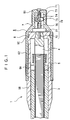
- Fig. 1 is a cross section showing a primary portion (first constant-force device) of a micrometer according to an embodiment of the present invention;
- Fig. 2 is a cross section showing another primary portion (second constant-force device) of the aforesaid embodiment; and
- Fig. 3 is an entire perspective view showing a conventional micrometer.
-
- As shown in Figs. 1 and 2, a
micrometer 1 according to the present embodiment has an approximately U-shaped frame (not shown), an anvil (not shown) held at one end of the frame, a spindle 4 screwed to the other end of theframe 1 through aretainer sleeve 3 and moved toward and away from the anvil 2, athimble 5 secured to the spindle 4 and fitted to an outer circumference of theretainer sleeve 3 as in themicrometer 100 of the aforesaid first conventional art. - On an outer side of an end remote from the end opposing the anvil, the
micrometer 1 is provided with anoperation sleeve 6 rotatable relative to the spindle 4 and integrally having afirst operation section 61 with a smaller diameter than the diameter of theretainer sleeve 3 and asecond operation section 62 fitted to an outer circumference of thethimble 5. - A
section 5A fitted to thesecond operation section 62 of thethimble 5 is thinner than asection 5B not fitted to thesecond operation section 62. Acircular groove 5C is formed on an outer circumference of the rear end of thethimble 5. - A
first accommodation space 7 and asecond accommodation space 8 are formed to themicrometer 1 respectively between thefirst operation section 61 of theoperation sleeve 6 and the outer end of the spindle 4, and between thegroove 5C formed on the outer circumference of thethimble 5 and thesecond operation section 62. Below-described first constant-force device 70 (see Fig. 1) and second constant-force device 80 (see Fig. 2) are selectively accommodated in the first and thesecond accommodation spaces - As shown in Fig. 1, the first constant-
force device 70 has ashaft 72 with one end screwed to the outer end of the spindle 4 and the other end rotatably supporting theoperation sleeve 6 through thescrew 71, afirst ratchet wheel 73 secured to an inner circumference of thefirst operation section 61, asecond ratchet wheel 74 meshed with thefirst ratchet wheel 73 in a rotatable and displaceable manner in axial direction relative to the spindle 4 though akey 75, a compressionhelical spring 76 for biasing thesecond ratchet wheel 74 toward thefirst ratchet wheel 73, and astopper 77 fixed to theshaft 72 for defining a position of the compressionhelical spring 76. - The
first ratchet wheel 73 and thesecond ratchet wheel 74 have a indented tooth meshing with each other formed at a regular pitch, where thefirst ratchet wheel 73 spins idly relative to thesecond ratchet wheel 74 when a more than predetermined load is applied to the spindle 4. - When the
operation sleeve 6 is rotated, thefirst ratchet wheel 73 fixed to theoperation section 61 is integrally rotated. Since thefirst ratchet wheel 73 and thesecond ratchet wheel 74 are meshed, thesecond ratchet wheel 74 is also rotated. Theshaft 72 is rotated through thekey 75 in accordance with the rotation of thesecond ratchet wheel 74, so that the spindle 4 screwed to theshaft 72 and thethimble 5 integrally mounted to the spindle 4 is rotated together. - On the other hand, when the
operation sleeve 6 is further rotated to rotate thefirst ratchet wheel 73 while applying a more than predetermined load to the spindle 4, since thesecond ratchet wheel 74 is unable to further rotate, thesecond ratchet wheel 74 escapes toward the compressionhelical spring 76 along thekey 75 against spring force of the compressionhelical spring 76. In other words, rotation force of thefirst ratchet wheel 73 is not transmitted to thesecond ratchet wheel 74, thus idly spinning theoperation sleeve 6. - As shown in Fig. 2, the second constant-
force device 80 has ahelical spring 81 as an elastic member with one end being engaged to the outer circumference of thethimble 5 and the other end being in contact with inner circumference of thesecond operation section 62 of theoperation sleeve 6, thehelical spring 81 being wound around thegroove 5C at the rear end of thethimble 5. When the second constant-force device 80 is provided, aholding block 83 having one end screwed to the spindle 4 and the other end rotatably holding theoperation sleeve 6 is provided in thefirst accommodation space 7. Incidentally, theholding block 83 may be formed in a shape corresponding to thefirst accommodation space 7, thus enhancing rigidity of thefirst operation section 61. - When the
operation sleeve 6 is rotated, since the other end of thehelical spring 81 is in contact with the inner circumference of thesecond operation section 62, thethimble 5 engaged to one end of thehelical spring 81 is also rotated, so that the spindle 4 integrally provided on thethimble 5 is rotated together with theoperation sleeve 6. - On the other hand, when a more than predetermined load is applied to the spindle 4 (between the
thimble 5 and the operation sleeve 6), the other end of thehelical spring 81 slips relative to thesecond operation section 62. In other words, the rotation force of theoperation sleeve 6 is not transmitted to thethimble 5, so that the operation sleeve 6 spins idly. - Next, a function of the present embodiment will be described below.
- The
operation sleeve 6 is rotated in a predetermined direction while disposing a workpiece between the anvil and the spindle 4. Specifically, theoperation sleeve 6 is rotated in a predetermined direction by either the double-handed operation for holding the frame with left hand and rotating thefirst operation section 61 with right hand or by single-handed operation for holding the frame and rotating thesecond operation section 62 with a single-handed. Then, the rotation force of theoperation sleeve 6 is transmitted to the spindle 4 and thethimble 5 through the first constant-force device 70 or the second constant-force device 80. When theoperation sleeve 6 is further rotated after one end of the spindle 4 is in contact with the workpiece, since a more than predetermined load is applied to the spindle 4, either the first constant-force device 70 or the second constant-force device 80 is actuated to idly spin theoperation sleeve 6. Specifically, thefirst ratchet wheel 73 slips relative to thesecond ratchet wheel 74 in the first constant-force device 70, or the other end of thehelical spring 81 slips relative to the inner circumference of thesecond operation section 62 in the second constant-force device 80. - According to the present embodiment, following effect can be obtained.
- In the present invention, the
thimble 5 and the spindle 4 are rotated through either the first constant-force device 70 or the second constant-force device 80 by rotating theoperation sleeve 6 integrally having thefirst operation section 61 and thesecond operation section 62. - During measurement, the
operation sleeve 6 is rotated while disposing a workpiece between the anvil and the spindle 4, thus sandwiching the workpiece between the anvil and the spindle 4. Theoperation sleeve 6 is further rotated under the above condition, so that either the first constant-force device 70 or the second constant-force device 80 is actuated when a more than predetermined load is applied to the spindle 4, thus idly spinning the operation sleeve. Since theoperation sleeve 6 integrally has thefirst operation section 61 and thesecond operation section 62, theoperation sleeve 6 is rotated in a predetermined direction by either the double-handed operation for holding the frame by left hand and rotating thefirst operation section 61 by right hand or by single-handed operation for holding the frame and rotating thesecond operation section 62 with a single-handed. Further, during both operations, the same operability as in the conventional operation can be obtained. - Since the arrangement of the frame, anvil,
retainer sleeve 3, spindle 4,thimble 5 andoperation sleeve 6 can be commonly used both in providing the first constant-force device 70 to thefirst accommodation space 7 and second constant-force device 80 to thesecond accommodation space 8, the number of components can be reduced. - Since only one constant-force device is installed in the
micrometer 1, there is not measurement error between measurement by the single-handed operation and the double-handed operation. - Since the
first accommodation space 7 and thesecond accommodation space 8 for accommodating the constant-force devices micrometer 1, one of the constant-force devices can be installed to one of the accommodation spaces, thus easily constructing themicrometer 1 having either the first constant-force device 70 or the second constant-force device 80. Further, the constant-force device can be selected from a plurality of devices, and the constant-force device can be easily exchanged. - Since the first constant-
force device 70 and the second constant-force device 80 employing known technique can be selectively installed to themicrometer 1, themicrometer 1 capable of both the single-handed operation and the double-handed operation can be easily constructed. Further, the same touch (such as sound and operation feeling) as in the conventional ratchet constant-force device can be obtained in the first constant-force device 70 and the same touch as so-called friction constant-force device using spring can be obtained in the second constant-force device 80. - Since the
section 5A fitted to thesecond operation section 62 of thethimble 5 is thinner than thesection 5B not fitted to thesecond operation section 62, the diameter of thesecond operation section 62 can be reduced, thus retaining operability and size of a conventional micrometer. - Incidentally, the scope of the present invention is not restricted to the above-described embodiments, but includes modifications and improvements as long as an object of the present invention can be attained.
- For instance, though a
helical spring 81 is used as the elastic member of the second constant-force device 80 in the above embodiment, the elastic member according to the present invention is not restricted to the above arrangement, but another component that works as the elastic member such as a plate spring may be used. - Though the
section 5A fitted to thesecond operation section 62 of thethimble 5 is thinner than thesection 5B not fitted to thesecond operation section 62 in the above embodiment, the shape of a conventional thimble may be used in the present invention. - Though the first and the second constant-
force device respective spaces micrometer 1 in the present embodiment, other constant-force device may be used instead of the first and the second constant-force devices
Claims (4)
- A micrometer comprising:an approximately U-shaped frame;an anvil held on one end of the frame;a spindle screwed to the other end of the frame through a retainer sleeve and movable toward and away from the anvil;a thimble secured to the spindle and fitted to an outer circumference of the retainer sleeve;an operation sleeve rotatable relative to the spindle, the operating sleeve integrally having, on an outer side of an end remote from the end opposing the anvil, a first operation section with a smaller diameter than the diameter of the retainer sleeve and a second operation section fitted to an outer circumference of the thimble; anda constant-force device provided on either between the first operation section of the operation sleeve and the outer end of the spindle or between the second operation section of the operation sleeve and the outer circumference of the thimble, the constant-force device idly spinning when a more than predetermined load is applied to the spindle.
- The micrometer according to Claim 1, wherein a first accommodation space and a second accommodation space for accommodating the constant-force device are formed respectively between the first operation section of the operation sleeve and the outer end of the spindle and between the second operation section of the operation sleeve and the outer circumference of the thimble.
- The micrometer according to Claim 2, the first constant-force device accommodated in the first accommodation space comprising: a first ratchet wheel fixed to an inner circumference of the first operation section; a second ratchet wheel meshing with the first ratchet wheel and unrotatable and displaceable relative to the spindle in an axis direction; and a compression coil spring for biasing the second ratchet wheel toward the first ratchet wheel,
the second constant-force device accommodated in the second accommodation space having an elastic member with one end being engaged to either one of the outer circumference of the thimble and the inner circumference of the second operation section and the other end being in contact with the other one of the outer circumference of the thimble and the inner circumference of the second operation section. - The micrometer according to any one of Claims 1 to 3, wherein a section of the thimble fitted to the second operation section being thinner than a section of the thimble not fitted to the second operation section.
Applications Claiming Priority (2)
| Application Number | Priority Date | Filing Date | Title |
|---|---|---|---|
| JP31964099 | 1999-11-10 | ||
| JP31964099A JP3724995B2 (en) | 1999-11-10 | 1999-11-10 | Micrometer |
Publications (2)
| Publication Number | Publication Date |
|---|---|
| EP1099928A1 true EP1099928A1 (en) | 2001-05-16 |
| EP1099928B1 EP1099928B1 (en) | 2003-09-10 |
Family
ID=18112563
Family Applications (1)
| Application Number | Title | Priority Date | Filing Date |
|---|---|---|---|
| EP00309945A Expired - Lifetime EP1099928B1 (en) | 1999-11-10 | 2000-11-09 | Micrometer |
Country Status (5)
| Country | Link |
|---|---|
| US (1) | US6463671B1 (en) |
| EP (1) | EP1099928B1 (en) |
| JP (1) | JP3724995B2 (en) |
| CN (1) | CN1118678C (en) |
| DE (1) | DE60005110T2 (en) |
Cited By (6)
| Publication number | Priority date | Publication date | Assignee | Title |
|---|---|---|---|---|
| FR2841644A1 (en) * | 2002-06-27 | 2004-01-02 | Skf Ab | APPARATUS FOR MEASURING THE DISTANCE BETWEEN TWO ROLLING BEARING HOUSINGS AND FOR MOUNTING A ROLLING BEARING INTO A WHEEL |
| CN101097128B (en) * | 2006-06-26 | 2010-06-16 | 三丰株式会社 | Digital displacement measuring instrument |
| EP2378238A1 (en) * | 2010-04-16 | 2011-10-19 | Mitutoyo Corporation | Displacement measuring instrument |
| EP2378237A1 (en) * | 2010-04-08 | 2011-10-19 | Mitutoyo Corporation | Micrometer |
| EP2574875A1 (en) * | 2011-09-28 | 2013-04-03 | Mitutoyo Corporation | Constant-force device for a micrometer |
| CN114351415A (en) * | 2021-12-16 | 2022-04-15 | 青岛胶州海尔洗涤电器有限公司 | Drainage structure, drainage method and washing machine |
Families Citing this family (11)
| Publication number | Priority date | Publication date | Assignee | Title |
|---|---|---|---|---|
| JP3751540B2 (en) * | 2000-07-26 | 2006-03-01 | 株式会社ミツトヨ | Measuring instrument |
| JP4732050B2 (en) | 2005-07-22 | 2011-07-27 | 株式会社ミツトヨ | Measuring instrument |
| US8091251B1 (en) * | 2009-11-22 | 2012-01-10 | Yanchen Zhang | High-speed measuring electronic digital outside micrometer |
| JP5851882B2 (en) | 2012-02-27 | 2016-02-03 | 株式会社ミツトヨ | Digital displacement measuring instrument |
| JP5986790B2 (en) * | 2012-04-23 | 2016-09-06 | 株式会社ミツトヨ | Micrometer |
| JP7097925B2 (en) | 2020-05-28 | 2022-07-08 | 株式会社ミツトヨ | Automatic measuring device |
| JP2024018645A (en) | 2022-07-29 | 2024-02-08 | 株式会社ミツトヨ | Automatic measuring device and its control method |
| JP2024112707A (en) | 2023-02-08 | 2024-08-21 | 株式会社ミツトヨ | Automatic measuring device and control method thereof |
| JP2024141250A (en) | 2023-03-29 | 2024-10-10 | 株式会社ミツトヨ | Displacement Measuring Instrument |
| JP2025035082A (en) | 2023-08-31 | 2025-03-13 | 株式会社ミツトヨ | Automatic Measuring Device |
| JP2025035083A (en) | 2023-08-31 | 2025-03-13 | 株式会社ミツトヨ | Automatic Measuring Device |
Citations (5)
| Publication number | Priority date | Publication date | Assignee | Title |
|---|---|---|---|---|
| EP0646764A2 (en) * | 1993-10-01 | 1995-04-05 | Mitutoyo Corporation | Digital display micrometer gauge |
| JPH07103749A (en) * | 1993-10-01 | 1995-04-18 | Mitsutoyo Corp | Constant pressure type measuring apparatus |
| EP0791801A2 (en) * | 1996-02-26 | 1997-08-27 | Mitutoyo Corporation | Micrometer |
| EP0864845A2 (en) * | 1997-03-12 | 1998-09-16 | Mitutoyo Corporation | Micrometer |
| EP0947801A2 (en) * | 1998-04-03 | 1999-10-06 | Mitutoyo Corporation | Micrometer |
Family Cites Families (8)
| Publication number | Priority date | Publication date | Assignee | Title |
|---|---|---|---|---|
| US141915A (en) * | 1873-08-19 | Improvement in micrometer-gages | ||
| US350513A (en) * | 1886-10-12 | Albeet l | ||
| US1143007A (en) * | 1914-01-14 | 1915-06-15 | Floyd Wilcox | Ratchet extension and protector for micrometer-calipers. |
| US1267075A (en) * | 1916-09-02 | 1918-05-21 | T R Almond Mfg Company | Micrometer-calipers. |
| US2267332A (en) * | 1940-12-09 | 1941-12-23 | Albert G Hagstrom | Direct reading positive measuring micrometer gauge |
| US2463261A (en) * | 1945-04-03 | 1949-03-01 | Chester E Wilbur | Micrometer head |
| US2835979A (en) * | 1956-12-03 | 1958-05-27 | Starrett L S Co | Micrometer nut and binder ring assembly |
| JPS5815101A (en) * | 1981-07-21 | 1983-01-28 | Mitsutoyo Mfg Co Ltd | Micrometer |
-
1999
- 1999-11-10 JP JP31964099A patent/JP3724995B2/en not_active Expired - Fee Related
-
2000
- 2000-11-03 CN CN00132347A patent/CN1118678C/en not_active Expired - Lifetime
- 2000-11-06 US US09/705,877 patent/US6463671B1/en not_active Expired - Lifetime
- 2000-11-09 DE DE60005110T patent/DE60005110T2/en not_active Expired - Lifetime
- 2000-11-09 EP EP00309945A patent/EP1099928B1/en not_active Expired - Lifetime
Patent Citations (5)
| Publication number | Priority date | Publication date | Assignee | Title |
|---|---|---|---|---|
| EP0646764A2 (en) * | 1993-10-01 | 1995-04-05 | Mitutoyo Corporation | Digital display micrometer gauge |
| JPH07103749A (en) * | 1993-10-01 | 1995-04-18 | Mitsutoyo Corp | Constant pressure type measuring apparatus |
| EP0791801A2 (en) * | 1996-02-26 | 1997-08-27 | Mitutoyo Corporation | Micrometer |
| EP0864845A2 (en) * | 1997-03-12 | 1998-09-16 | Mitutoyo Corporation | Micrometer |
| EP0947801A2 (en) * | 1998-04-03 | 1999-10-06 | Mitutoyo Corporation | Micrometer |
Non-Patent Citations (1)
| Title |
|---|
| PATENT ABSTRACTS OF JAPAN vol. 1995, no. 07 31 August 1995 (1995-08-31) * |
Cited By (9)
| Publication number | Priority date | Publication date | Assignee | Title |
|---|---|---|---|---|
| FR2841644A1 (en) * | 2002-06-27 | 2004-01-02 | Skf Ab | APPARATUS FOR MEASURING THE DISTANCE BETWEEN TWO ROLLING BEARING HOUSINGS AND FOR MOUNTING A ROLLING BEARING INTO A WHEEL |
| CN101097128B (en) * | 2006-06-26 | 2010-06-16 | 三丰株式会社 | Digital displacement measuring instrument |
| EP2378237A1 (en) * | 2010-04-08 | 2011-10-19 | Mitutoyo Corporation | Micrometer |
| US8296966B2 (en) | 2010-04-08 | 2012-10-30 | Mitutoyo Corporation | Micrometer |
| EP2378238A1 (en) * | 2010-04-16 | 2011-10-19 | Mitutoyo Corporation | Displacement measuring instrument |
| US8413348B2 (en) | 2010-04-16 | 2013-04-09 | Mitutoyo Corporation | Displacement measuring instrument |
| EP2574875A1 (en) * | 2011-09-28 | 2013-04-03 | Mitutoyo Corporation | Constant-force device for a micrometer |
| US8833535B2 (en) | 2011-09-28 | 2014-09-16 | Mitutoyo Corporation | Constant-force device and micrometer |
| CN114351415A (en) * | 2021-12-16 | 2022-04-15 | 青岛胶州海尔洗涤电器有限公司 | Drainage structure, drainage method and washing machine |
Also Published As
| Publication number | Publication date |
|---|---|
| DE60005110T2 (en) | 2004-03-25 |
| CN1296164A (en) | 2001-05-23 |
| DE60005110D1 (en) | 2003-10-16 |
| JP3724995B2 (en) | 2005-12-07 |
| EP1099928B1 (en) | 2003-09-10 |
| US6463671B1 (en) | 2002-10-15 |
| CN1118678C (en) | 2003-08-20 |
| JP2001141402A (en) | 2001-05-25 |
Similar Documents
| Publication | Publication Date | Title |
|---|---|---|
| EP1099928B1 (en) | Micrometer | |
| EP0646764B1 (en) | Digital display micrometer gauge | |
| EP1892497B1 (en) | Caliper gauge | |
| US10071718B2 (en) | Setting device, particularly a motor vehicle parking brake | |
| JP5364463B2 (en) | Webbing take-up device | |
| EP2574875B1 (en) | Constant-force device for a micrometer | |
| JP2005308118A (en) | Worm gear mechanism and electric power steering device equipped with the worm gear mechanism | |
| JP3623038B2 (en) | Micrometer | |
| WO2013145973A1 (en) | Damper and operation unit | |
| US20200109771A1 (en) | Ball screw device | |
| JP5449075B2 (en) | Webbing take-up device | |
| CN111140627A (en) | Ball screw device | |
| CN101598524A (en) | micrometer | |
| JP2007093331A (en) | Measuring instrument | |
| EP2378238B1 (en) | Displacement measuring instrument | |
| US20030010159A1 (en) | Biasing arrangement for a pawl of a reversible ratchet-type wrench | |
| US6397700B1 (en) | Dual dial rod speed changing indicator | |
| JP5426486B2 (en) | Displacement measuring instrument | |
| JP5130185B2 (en) | Transmission and measuring machine | |
| JP3671135B2 (en) | Rack and pinion steering device | |
| JP2695765B2 (en) | Wire operating device for bicycle transmission | |
| JP7274338B2 (en) | steering device | |
| JPH08152057A (en) | Gear device | |
| JP7334644B2 (en) | steering column device | |
| JPS58152944A (en) | Brake mechanism |
Legal Events
| Date | Code | Title | Description |
|---|---|---|---|
| PUAI | Public reference made under article 153(3) epc to a published international application that has entered the european phase |
Free format text: ORIGINAL CODE: 0009012 |
|
| AK | Designated contracting states |
Kind code of ref document: A1 Designated state(s): DE FR GB |
|
| AX | Request for extension of the european patent |
Free format text: AL;LT;LV;MK;RO;SI |
|
| 17P | Request for examination filed |
Effective date: 20011026 |
|
| AKX | Designation fees paid |
Free format text: DE FR GB |
|
| GRAH | Despatch of communication of intention to grant a patent |
Free format text: ORIGINAL CODE: EPIDOS IGRA |
|
| GRAS | Grant fee paid |
Free format text: ORIGINAL CODE: EPIDOSNIGR3 |
|
| GRAA | (expected) grant |
Free format text: ORIGINAL CODE: 0009210 |
|
| AK | Designated contracting states |
Kind code of ref document: B1 Designated state(s): DE FR GB |
|
| REG | Reference to a national code |
Ref country code: GB Ref legal event code: FG4D |
|
| REF | Corresponds to: |
Ref document number: 60005110 Country of ref document: DE Date of ref document: 20031016 Kind code of ref document: P |
|
| ET | Fr: translation filed | ||
| PLBE | No opposition filed within time limit |
Free format text: ORIGINAL CODE: 0009261 |
|
| STAA | Information on the status of an ep patent application or granted ep patent |
Free format text: STATUS: NO OPPOSITION FILED WITHIN TIME LIMIT |
|
| 26N | No opposition filed |
Effective date: 20040614 |
|
| REG | Reference to a national code |
Ref country code: FR Ref legal event code: PLFP Year of fee payment: 16 |
|
| REG | Reference to a national code |
Ref country code: FR Ref legal event code: PLFP Year of fee payment: 17 |
|
| REG | Reference to a national code |
Ref country code: FR Ref legal event code: PLFP Year of fee payment: 18 |
|
| REG | Reference to a national code |
Ref country code: DE Ref legal event code: R082 Ref document number: 60005110 Country of ref document: DE Representative=s name: KEIL & SCHAAFHAUSEN PATENTANWAELTE PARTGMBB, DE Ref country code: DE Ref legal event code: R082 Ref document number: 60005110 Country of ref document: DE Representative=s name: KEIL & SCHAAFHAUSEN PATENT- UND RECHTSANWAELTE, DE |
|
| PGFP | Annual fee paid to national office [announced via postgrant information from national office to epo] |
Ref country code: DE Payment date: 20191121 Year of fee payment: 20 |
|
| PGFP | Annual fee paid to national office [announced via postgrant information from national office to epo] |
Ref country code: FR Payment date: 20191120 Year of fee payment: 20 |
|
| PGFP | Annual fee paid to national office [announced via postgrant information from national office to epo] |
Ref country code: GB Payment date: 20191120 Year of fee payment: 20 |
|
| REG | Reference to a national code |
Ref country code: DE Ref legal event code: R071 Ref document number: 60005110 Country of ref document: DE |
|
| REG | Reference to a national code |
Ref country code: GB Ref legal event code: PE20 Expiry date: 20201108 |
|
| PG25 | Lapsed in a contracting state [announced via postgrant information from national office to epo] |
Ref country code: GB Free format text: LAPSE BECAUSE OF EXPIRATION OF PROTECTION Effective date: 20201108 |