EP1099884A2 - Controller of toroidal continuously variable transmission - Google Patents
Controller of toroidal continuously variable transmission Download PDFInfo
- Publication number
- EP1099884A2 EP1099884A2 EP00124555A EP00124555A EP1099884A2 EP 1099884 A2 EP1099884 A2 EP 1099884A2 EP 00124555 A EP00124555 A EP 00124555A EP 00124555 A EP00124555 A EP 00124555A EP 1099884 A2 EP1099884 A2 EP 1099884A2
- Authority
- EP
- European Patent Office
- Prior art keywords
- pressure
- oil chamber
- port
- control valve
- speed ratio
- Prior art date
- Legal status (The legal status is an assumption and is not a legal conclusion. Google has not performed a legal analysis and makes no representation as to the accuracy of the status listed.)
- Withdrawn
Links
Images


Classifications
-
- F—MECHANICAL ENGINEERING; LIGHTING; HEATING; WEAPONS; BLASTING
- F16—ENGINEERING ELEMENTS AND UNITS; GENERAL MEASURES FOR PRODUCING AND MAINTAINING EFFECTIVE FUNCTIONING OF MACHINES OR INSTALLATIONS; THERMAL INSULATION IN GENERAL
- F16H—GEARING
- F16H37/00—Combinations of mechanical gearings, not provided for in groups F16H1/00 - F16H35/00
- F16H37/02—Combinations of mechanical gearings, not provided for in groups F16H1/00 - F16H35/00 comprising essentially only toothed or friction gearings
- F16H37/06—Combinations of mechanical gearings, not provided for in groups F16H1/00 - F16H35/00 comprising essentially only toothed or friction gearings with a plurality of driving or driven shafts; with arrangements for dividing torque between two or more intermediate shafts
- F16H37/08—Combinations of mechanical gearings, not provided for in groups F16H1/00 - F16H35/00 comprising essentially only toothed or friction gearings with a plurality of driving or driven shafts; with arrangements for dividing torque between two or more intermediate shafts with differential gearing
- F16H37/0833—Combinations of mechanical gearings, not provided for in groups F16H1/00 - F16H35/00 comprising essentially only toothed or friction gearings with a plurality of driving or driven shafts; with arrangements for dividing torque between two or more intermediate shafts with differential gearing with arrangements for dividing torque between two or more intermediate shafts, i.e. with two or more internal power paths
- F16H37/084—Combinations of mechanical gearings, not provided for in groups F16H1/00 - F16H35/00 comprising essentially only toothed or friction gearings with a plurality of driving or driven shafts; with arrangements for dividing torque between two or more intermediate shafts with differential gearing with arrangements for dividing torque between two or more intermediate shafts, i.e. with two or more internal power paths at least one power path being a continuously variable transmission, i.e. CVT
- F16H37/086—CVT using two coaxial friction members cooperating with at least one intermediate friction member
-
- F—MECHANICAL ENGINEERING; LIGHTING; HEATING; WEAPONS; BLASTING
- F16—ENGINEERING ELEMENTS AND UNITS; GENERAL MEASURES FOR PRODUCING AND MAINTAINING EFFECTIVE FUNCTIONING OF MACHINES OR INSTALLATIONS; THERMAL INSULATION IN GENERAL
- F16H—GEARING
- F16H15/00—Gearings for conveying rotary motion with variable gear ratio, or for reversing rotary motion, by friction between rotary members
- F16H15/02—Gearings for conveying rotary motion with variable gear ratio, or for reversing rotary motion, by friction between rotary members without members having orbital motion
- F16H15/04—Gearings providing a continuous range of gear ratios
- F16H15/06—Gearings providing a continuous range of gear ratios in which a member A of uniform effective diameter mounted on a shaft may co-operate with different parts of a member B
- F16H15/32—Gearings providing a continuous range of gear ratios in which a member A of uniform effective diameter mounted on a shaft may co-operate with different parts of a member B in which the member B has a curved friction surface formed as a surface of a body of revolution generated by a curve which is neither a circular arc centered on its axis of revolution nor a straight line
- F16H15/36—Gearings providing a continuous range of gear ratios in which a member A of uniform effective diameter mounted on a shaft may co-operate with different parts of a member B in which the member B has a curved friction surface formed as a surface of a body of revolution generated by a curve which is neither a circular arc centered on its axis of revolution nor a straight line with concave friction surface, e.g. a hollow toroid surface
- F16H15/38—Gearings providing a continuous range of gear ratios in which a member A of uniform effective diameter mounted on a shaft may co-operate with different parts of a member B in which the member B has a curved friction surface formed as a surface of a body of revolution generated by a curve which is neither a circular arc centered on its axis of revolution nor a straight line with concave friction surface, e.g. a hollow toroid surface with two members B having hollow toroid surfaces opposite to each other, the member or members A being adjustably mounted between the surfaces
-
- F—MECHANICAL ENGINEERING; LIGHTING; HEATING; WEAPONS; BLASTING
- F16—ENGINEERING ELEMENTS AND UNITS; GENERAL MEASURES FOR PRODUCING AND MAINTAINING EFFECTIVE FUNCTIONING OF MACHINES OR INSTALLATIONS; THERMAL INSULATION IN GENERAL
- F16H—GEARING
- F16H61/00—Control functions within control units of change-speed- or reversing-gearings for conveying rotary motion ; Control of exclusively fluid gearing, friction gearing, gearings with endless flexible members or other particular types of gearing
- F16H61/66—Control functions within control units of change-speed- or reversing-gearings for conveying rotary motion ; Control of exclusively fluid gearing, friction gearing, gearings with endless flexible members or other particular types of gearing specially adapted for continuously variable gearings
- F16H61/664—Friction gearings
- F16H61/6648—Friction gearings controlling of shifting being influenced by a signal derived from the engine and the main coupling
-
- F—MECHANICAL ENGINEERING; LIGHTING; HEATING; WEAPONS; BLASTING
- F16—ENGINEERING ELEMENTS AND UNITS; GENERAL MEASURES FOR PRODUCING AND MAINTAINING EFFECTIVE FUNCTIONING OF MACHINES OR INSTALLATIONS; THERMAL INSULATION IN GENERAL
- F16H—GEARING
- F16H37/00—Combinations of mechanical gearings, not provided for in groups F16H1/00 - F16H35/00
- F16H37/02—Combinations of mechanical gearings, not provided for in groups F16H1/00 - F16H35/00 comprising essentially only toothed or friction gearings
- F16H37/06—Combinations of mechanical gearings, not provided for in groups F16H1/00 - F16H35/00 comprising essentially only toothed or friction gearings with a plurality of driving or driven shafts; with arrangements for dividing torque between two or more intermediate shafts
- F16H37/08—Combinations of mechanical gearings, not provided for in groups F16H1/00 - F16H35/00 comprising essentially only toothed or friction gearings with a plurality of driving or driven shafts; with arrangements for dividing torque between two or more intermediate shafts with differential gearing
- F16H37/0833—Combinations of mechanical gearings, not provided for in groups F16H1/00 - F16H35/00 comprising essentially only toothed or friction gearings with a plurality of driving or driven shafts; with arrangements for dividing torque between two or more intermediate shafts with differential gearing with arrangements for dividing torque between two or more intermediate shafts, i.e. with two or more internal power paths
- F16H37/084—Combinations of mechanical gearings, not provided for in groups F16H1/00 - F16H35/00 comprising essentially only toothed or friction gearings with a plurality of driving or driven shafts; with arrangements for dividing torque between two or more intermediate shafts with differential gearing with arrangements for dividing torque between two or more intermediate shafts, i.e. with two or more internal power paths at least one power path being a continuously variable transmission, i.e. CVT
- F16H2037/088—Power split variators with summing differentials, with the input of the CVT connected or connectable to the input shaft
Definitions
- This invention relates to speed ratio control of a toroidal continuously variable transmission.
- Tokkai Hei 5-39847 published by the Japanese Patent Office in 1993 discloses a toroidal continuously variable transmission.
- This toroidal continuously variable transmission comprises an input disk and output disk which can rotate relative to each other on a common axis, and a pair of friction rollers gripped between these disks.
- the toroidal continuously variable transmission varies an inclination (gyration angle) of the friction roller, and transmits the rotation between the disks at an arbitrary speed ratio.
- the gyration angle of the friction roller varies due to the displacement of trunnions supporting the friction roller in the direction perpendicular to the rotation axis due to an oil pressure.
- the displacement of the trunnion varies the position of the contact points with the input disk and output disk of the friction roller. Due to the variation of these contact points, the input disk and output disk exert a component force which varies the gyration angle of the friction roller, and as a result, the gyration angle of the friction roller varies.
- Servo pistons are fixed to the trunnions.
- the trunnions displace according to the differential pressure of oil chambers on both sides of the servo piston, and the variation of the gyration angle of the friction roller, i.e. the variation of the speed ratio, is faster the larger the differential pressure.
- a speed ratio control valve selectively connects the two oil chambers on either side of the servo pistons to an oil pressure source and a drain according to the displacement of a spool.
- the spool is joined to a step motor, and the friction roller is controlled to a gyration angle corresponding to the target speed ratio by inputting a signal corresponding to the target speed ratio to the step motor.
- the speed ratio may vary sharply.
- a sharp downshift unrelated to the driver's intention is produced.
- the differential pressure can be prevented from becoming excessive by controlling the stroke range of the spool. However if the stroke range of the spool is limited, it is possible that the required differential pressure may not be produced when the oil pressure of an oil pressure source drops.
- this invention provides a controller for a toroidal continuously variable transmission of a vehicle.
- the transmission comprises an input disk which rotates about a rotation shaft, an output disk which rotates about the rotation shaft, a power roller gripped by the input disk and the output disk and transmitting a torque between the input disk and output disk, and a trunnion which drives the power roller in a direction perpendicular to the rotation shaft according to a differential pressure of a first oil chamber and a second oil chamber.
- the transmission causes a downshift when the second oil chamber is at a higher pressure than the first oil chamber, and causing an upshift when the first oil chamber is at a higher pressure than the second oil chamber.
- the first oil chamber is connected to a first passage and the second oil chamber is connected to a second oil passage.
- the controller comprises a speed ratio control valve which controls a direction and a flowrate of oil in the first oil passage and the second oil passage. and a pressure control valve which limits a maximum differential pressure of the first oil chamber and the second oil chamber when the transmission causes a downshift smaller than a maximum differential pressure of the first oil chamber and the second oil chamber when the transmission causes an upshift.
- Fig. 1 is a schematic diagram of a toroidal continuously variable transmission according to this invention.
- Figs. 2A, 2B are oil pressure circuit diagrams of the toroidal continuously variable transmission according to this invention.
- Fig. 3 is a diagram describing the relation between a stroke distance of a spool of a speed ratio control valve and various pressures according to this invention.
- Fig. 4 is a partial oil pressure circuit diagram of the toroidal continuously variable transmission according to a second embodiment of this invention.
- Fig. 5 is a diagram showing the relation between the stroke distance of the spool of the speed ratio control valve and a supply pressure thereof according to the second embodiment of this invention.
- Fig. 6 is similar to Fig. 3, but showing a third embodiment of this invention.
- Fig. 7 is similar to Fig. 5, but showing the third embodiment of this invention.
- Fig. 8 is a diagram showing the relation between the stroke distance of the spool of the speed ratio control valve and a differential pressure according to the first, second and third embodiments of this invention in comparison with a toroidal continuously variable transmission according to the prior art.
- Fig. 9 is a schematic diagram of an infinite speed ratio transmission device according to a fourth embodiment of this invention.
- Fig. 10 is a schematic diagram of a control device of the infinite speed ratio transmission device according to the fourth embodiment of this invention.
- Fig. 11 is an oil pressure circuit diagram of the infinite speed ratio transmission device according to the fourth embodiment of this invention.
- Fig. 12 is a schematic cross-sectional view of the toroidal continuously variable transmission applied to the infinite speed ratio transmission device.
- Fig. 13 is a diagram describing the relation between the signal pressure output by a control unit according to the fourth embodiment of this invention and various oil pressures.
- Fig. 14 is a flowchart describing a differential pressure control routine performed by a the control unit according to the fourth embodiment of this invention.
- Fig. 15 is a diagram describing a limitation of the differential pressure applied by the differential pressure control routine when a vehicle is moving forward in a power circulation mode.
- Fig. 16 is a diagram describing the contents of a map of a parameter K c used when the differential pressure control routine determines a differential pressure limiting value in a direct mode.
- Fig. 17 is a diagram describing a limitation of the differential pressure applied by the differential pressure control routine when a vehicle is moving backwards in the power circulation mode.
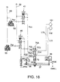
- Fig. 18 is an oil pressure circuit diagram of the infinite speed ratio transmission device according to a fifth embodiment of this invention.
- Fig. 19 is a diagram showing a relation between the signal pressure and a control pressure according to the fifth embodiment of this invention.
- Fig. 20 is a flowchart describing the differential pressure control routine performed by the control unit according to the fifth embodiment of this invention.
- Fig. 21 is an oil pressure circuit diagram of the infinite speed ratio transmission device according to a sixth embodiment of this invention.
- Fig. 22 is a diagram showing a relation between the signal pressure and the control pressure according to the sixth embodiment of this invention.
- FIG. 23 is a diagram showing a general speed ratio characteristic of an infinite speed ratio transmission device
- a double cavity toroidal continuously variable transmission (abbreviated hereafter as toroidal CVT) 1 comprises two sets of toroidal units 18, 20 housed in a transmission case 11.
- the first toroidal unit 18 comprises a pair of power rollers 18C, 18D gripped between an input disk 18A and output disk 18B.
- the second toroidal unit 20 comprises a pair of power rollers 20C, 20D gripped between an input disk 20A and output disk 20B.
- the input disks 18A, 20A rotate together with a shaft 16A.
- the output disks 18B, 20B are fixed to a hollow shaft 13 which is fitted free to rotate on the outer circumference of the shaft 16A
- the rotation of the hollow shaft 13 is output to an output shaft 33 via an output gear 14, counter gear 17, counter shaft 31 and intermediate gears 32.
- a rotation torque is input from an input shaft 16 to the shaft 16A.
- This rotation torque is transmitted from an engine 79 to the input shaft 16 via a torque converter 27 and a forward/reverse change-over clutch 28.
- the power roller 18C is supported by a trunnion 104, and the power roller 18D is supported by a trunnion 105.
- a server piston 106 is fixed to a trunnion 104.
- the servo piston 106 drives the trunnion 104 in the direction of a trunnion shaft 104A perpendicular to the shaft 16A according to a difference of oil pressures supplied to an upshift oil chamber 101 and a downshift oil chamber 102 on both sides.
- the trunnion 104 can also perform a rotational displacement around this trunnion shaft 104A.
- a trunnion 105 comprises a servo piston 107 which responds to the differential pressure of the upshift oil chamber 101 and downshift oil chamber 102 and drives the trunnion 105 along a trunnion shaft 105A.
- the positions of the upshift oil chamber 101 and downshift oil chamber 102 of the trunnion 104 are the reverse of the positions of the upshift oil chamber 101 and downshift oil chamber 102 of the trunnion 105, so the trunnions 104, 105 are always driven in reverse directions.
- the second toroidal unit 20 supports the power roller 20C by a trunnion 114 provided with a servo piston 116, and supports the power roller 20D by a trunnion 115 provided with a servo piston 117.
- the servo piston 116 responds to the differential pressure of the upshift oil chamber 101 and downshift oil chamber 102 which are disposed identically to those of the servo piston 106, and drives the trunnion 114 along a trunnion shaft 114A.
- the servo piston 117 responds to the differential pressure of the upshift oil chamber 101 and downshift oil chamber 102 which are disposed identically to those of the servo piston 107, and drives the trunnion 115 along a trunnion shaft 115A.
- Pressurized oil is supplied to the upshift oil chamber 101 and downshift oil chamber 102 via an oil pressure circuit shown in the diagram in order to generate a differential pressure between the upshift and downshift oil chambers 101, 102 based on a target speed ratio.
- the oil pressure circuit comprises a speed ratio control valve 70, forward/reverse change-over valve 81, pressure control valve 200 and reverse speed ratio control valve 80.
- valves process a line pressure PL supplied by the line pressure circuit 150 from an oil pressure source, and supply processed pressures to a passage 176 leading to the upshift oil chambers 101 and a passage 177 leading to the downshift oil chambers 102.
- the rotation of the engine of the vehicle is input to the CVT 1 via the forward/reverse change-over clutch 28.
- the forward/reverse change-over valve 81 changes over in synchronism with the forward/reverse change-over clutch 28, and connects the speed ratio control valve 70 or reverse speed ratio control valve 80 to the passages 176, 177.
- the forward/reverse change-over valve 81 comprises a spool 81B supported by a spring 81A, and ports 81C, 81D, 81E, 81F, 81G, 81H, 81I, 81J facing the spool 81B.
- the port 81C communicates with the passage 176, and the port 81D communicates with the passage 177.
- the port 81E communicates with the line pressure circuit 150.
- the port 81F communicates with a passage 181
- the port 81G communicates with a passage 180
- the port 81H communicates with a passage 174
- the port 81I communicates with a passage 179
- the port 81J communicates with a passage 175.
- the spool 81B is driven by a lever 77 in synchronism with the forward/reverse change-over clutch 28.
- the port 81H is connected to the port 81
- the port 81J is connected to the port 81D
- the other ports are shut off as shown in the diagram.
- the port 81E is connected to the port 81F
- the port 81C is connected to the port 81G
- the port 811 is connected to the port 81D
- the other ports are shut off.
- the speed ratio control valve 70 comprises a spool 73 elastically supported by a spring 73C, and ports 70D, 70E, 70F, 70G, 70H facing the spool 73.
- the port 70D communicates with a drain, and the port 70E is connected to a high-pressure supply passage 151 from the pressure control valve 200.
- the port 70F is connected to the line pressure circuit 150.
- the port 70G is connected to the passage 174 leading to the port 81H of the forward/reverse change-over valve 81, and the port 70H is connected to the passage 175 leading to the port 81J of the forward/reverse change-over valve 81.
- the spool 73 is driven by a step motor, and displaces between a position in which the port 70G is connected to the port 70E while the port 70H is connected to the port 70F, and a position in which the port 70G is connected to the port 70F while the port 70H is connected to the port 70D.
- This displacement therefore causes a change in the pressure of the upshift oil chambers 101 and in the pressure of the downshift oil chambers 102.
- a command corresponding to the target speed ratio is input to the step motor so that the spool 73 displaces, and the gyration angles of the power rollers 18C, 18D, 20C, 20D of the CVT 1 coincide with the angle corresponding to the target speed ratio.
- a feedback mechanism causes the spool 73 to displace in the opposite direction to the displacement due to the step motor.
- the spool 73 is held in a position where the displacements due to the step motor and feedback mechanism are balanced.
- the reverse speed ratio control valve 80 comprises a spool 80B elastically supported by a spring 80A, and ports 80C, 80D, 80E facing a spool 80B
- the port 80C communicates with the port 81F of the forward/reverse change-over valve 81 via a passage 181.
- the port 80D communicates with the port 811 of the forward/reverse change-over valve 81 via the passage 179.
- the port 80E communicates with the port 81G of the forward/reverse change-over valve 81 via the passage 180.
- the spool 80B is driven by a precess cam 76 via an L-shaped link 75.
- the precess cam 76 is fixed to one of the trunnion shafts 104A, 105A, 114A, 115A, and transmits the rotational displacement of the trunnions 104, 105, 114, 115 and the displacement in the direction of the trunnion shafts 104A, 105A, 114A, 115A to a spool 88B via the L-shaped link 75.
- the forward/reverse change-over valve 81 connects the ports 81E and 81F, connects the port 81G to the port 81C leading to the upshift oil chambers 101, and connects the port 811 to the port 81F leading to the downshift oil chambers 102.
- the line pressure PL is supplied to the port 80C of the reverse speed ratio control valve 80, the port 80E is connected to the upshift oil chambers 101, and the port 80D is connected to the downshift oil chambers 102.
- the target speed ratio of the CVT 1 when the vehicle is reversing is set to a constant value, and when the real speed ratio of the CVT 1 is less than the target speed ratio, the precess cam 76 moves the spool 8SB upwards in Fig. 2B via the L-shaped link 75 so that the line pressure PL is supplied to the downshift oil chambers 102, and the CVT 1 performs a downshift.
- the precess cam 76 moves the spool 88B downwards in Fig. 2B via the L-shaped link 75 so that the line pressure PL is supplied to the upshift oil chambers 101, and the CVT 1 performs an upshift.
- the speed ratio of the CVT 1 when the vehicle is reversing is controlled to the fixed target speed ratio.
- the pressure control valve 200 is provided to control the oil pressure of the port 70E of the speed ratio control valve 70.
- the pressure control valve 200 comprises a spool 202 elastically supported by a spring 201, and ports 200A, 200B, 200C, 200D together with a drain port 200E facing the spool 202.
- the ports 200A, 200B communicate with the port 70E of the speed ratio control valve 70 via the passage 151.
- the ports 200D, 200C communicate with the line pressure passage 150.
- the spool 202 displaces to a position where the equation (3) is satisfied as the line pressure PL, i.e. the force FL, varies.
- the spool 202 displaces in the left-hand direction of Fig. 2B, and due to the narrowing of the passage between the port 200B and the drain port 200E, the oil pressure Phi of the port 70E of the speed ratio control valve 70 is caused to rise.
- the pressure control valve 200 shown in Fig. 2B corresponds to the case where the line pressure PL is zero and accordingly the oil pressure Phi is also zero, but when the line pressure PL is not zero, the oil pressure Phi is also not zero.
- the spool 73 of the speed ratio control valve 70 is driven downwards in Fig. 2B by the step motor.
- the line pressure PL is supplied to the upshift oil chambers 101 via the passage 176, and the downshift oil chambers 102 communicate with the drain port 70D via the passage 177.
- the servo pistons 106, 107, 116, 117 displace according to this differential pressure, the gyration angles of the power rollers 18C, 18D, 20C, 20D vary, and the speed ratio of the CVT 1 is decreased.
- the spool 73 of the speed ratio control valve 70 is driven upwards in Fig. 2B by the step motor.
- the line pressure PL is supplied to the downshift oil chambers 102 via the passage 177, and the downshift oil chambers 102 communicate with the port 70E via the passage 177.
- the oil pressure Phi due to the pressure control valve 200 acts on the port 70E. Therefore, the servo pistons 106, 107, 116, 117 displace according to the differential pressure of the line pressure PL and the oil pressure Phi, the gyration angles of the power rollers 18C, 18D, 20C, 20D are made to vary, and the speed ratio of the CVT 1 is increased.
- the oil pressure Phi rises according to the increase of the line pressure PL as described above. Therefore, the maximum value of the differential pressure between the upshift oil chambers 101 and downshift oil chambers 102 during a downshift operation is less than the maximum value of the differential pressure during an upshift operation.
- the line pressure PL is supplied from the port 70F to the upshift oil chambers 101, and the downshift oil chambers 102 are connected to the drain via the port 70D. Therefore, the pressure Phi is equal to the line pressure PL, and the pressure Plow is zero.
- the pressure Phi decreases and the pressure Plow rises. Due to the rise of the spool 73, it communicates with the upshift oil chambers 101.
- the pressure Phc is a pressure which varies according to the line pressure PL , and is less than the line pressure PL, and provided that the line pressure PL is not zero, it is never zero.
- the decrease rate of the pressure Phi relative to increase of the stroke distance Xc is less than the increase rate of the pressure Plow.
- the power rollers 18C, 18D, 20C, 20D are in a state such that torque transmission between the disks does not take place.
- this state of the power rollers 18C, 18D, 20C, 20D will be referred to as the neutral state, and the stroke position of the spool 73 of the speed ratio control valve 70 at that time will be referred to as the neutral position.
- the differential pressure ⁇ Pdown between Phi and Plow which can be applied during a downshift operation is less than the differential pressure which can be applied during an upshift operation.
- the solid line D shows the variation of the differential pressure ⁇ Pdown when the pressure control valve 200 is not provided
- the dotted line A in the figure shows the differential pressure ⁇ Pdown in this embodiment.
- a maximum differential pressure ⁇ Pc of this embodiment where the pressure control valve 200 is provided is suppressed low relative to a maximum differential pressure ⁇ Pcmax when the pressure control valve 200 is not provided at a maximum stroke distance Xcmax.
- the differential pressure ⁇ Pdown in the downshift direction is determined by the pressure Phi.
- the pressure Phi varies according to the pressure Phc controlled by the pressure control valve 200.
- the differential pressure ⁇ Pdown therefore varies according to the spring constant K1 of the spring 201 of the pressure control valve 200.
- the gyration angles of the power rollers 18C, 18D, 20C, 20D are made to vary, and the speed ratio of the CVT 1 is varied.
- the variation of the speed ratio is fed back to the speed ratio control valve 70 via the feedback mechanism, and when the real speed ratio reaches the target speed ratio, the speed ratio control valve returns the servo pistons 106, 107, 116, 117 to the neutral position.
- FIG. 3 is the stroke position of the spool 73 when the transmitted torque is zero, and when the transmitted torque increases, the stroke position of the spool 73 shift to the left of the figure to maintain the power rollers 18C, 18D, 20C, 20D in the neutral position.
- ⁇ Pdown ( Xc3 ) ⁇ Pc3 + ⁇ Pc0
- a pressure control valve 210 is interposed in the passage 175.
- the pressure control valve 210 comprises a spool 212 elastically supported by a spring 211, together with ports 210A, 210B, 210C and a drain port 210D facing the spool 212.
- the ports 210A, 210B communicate with the port 70H of the speed ratio control valve 70.
- the port 210C permanently communicates with the passage 175 and the port 210B at the same time.
- the differential pressure ⁇ Pdown is shown by a double dotted line B.
- the stroke distance Xc of the spool 73 reaches Xcd, it increases at the same rate as if the pressure control valve 200 were not provided. Let this section be a section ⁇ 1. After the stroke distance Xc of the spool 73 reaches Xcd, as the pressure Plow then becomes constant, the increase rate of the differential pressure ⁇ Pdown is more gradual than the solid line D, as shown by the double dotted line B.
- the section from Xcd to Xcmax be a section ⁇ 2.
- the maximum differential pressure at the maximum stroke distance Xcmax is a maximum differential pressure ⁇ Pc which is lower than the maximum differential pressure ⁇ Pcmax that is generated when the pressure control valve 210 is not provided.
- the value of this maximum differential pressure ⁇ Pc can be arbitrarily set by setting the spring constant K2 of the spring 21 and the stroke distance X2d of the spool 212. Therefore, according also to this embodiment, the disadvantage of a sharp downshift occurring unrelated to the driver's intention due to sticking of the spool 73 or faulty operation of the step motor can be prevented without limiting the stroke range of the spool 73.
- the speed ratio variation characteristics of the CVT 1 vary in two stages in the section ⁇ 1 and the section ⁇ 2.
- the rate of speed ratio variation during a downshift is slower than in the case where the pressure control valve 210 is not provided. Therefore, according to this embodiment, a sharp downshift can be prevented without largely affecting the speed ration variation response of the CVT 1.
- a pressure control valve 220 is interposed between the ports 70G, 70H of the speed ratio control valve 70 and the passages 174, 175.
- the pressure control valve 220 comprises a spool 222 elastically supported by a spring 221, and ports 220A, 220B, 220C, 220D and 220E facing the spool 222.
- the line pressure PL is led from the line pressure passage 150 the port to the port 220A.
- the port 220B communicates with the port 70G of the speed ratio control valve 70.
- the port 220E communicates with the passage 175.
- the port 220C, 220D communicate with the passage 174.
- the port 220C communicates with the port 220A to which the line pressure PL is led, and the port 220B which communicates with the drain is shut off. Therefore, the pressure Phi also rises according to the rise of the pressure Plow, and the differential pressure ⁇ Pdown in the downshift direction subsequently maintains a constant value -Ps3d.
- the stroke distance of the spool 73 when the differential pressure ⁇ Pdown is the constant value -Ps3d be Xcl.
- the differential pressure ⁇ Pdown in the downshift direction is shown by a broken line C.
- the stroke distance Xc of the spool 73 is equal to or less than Xcl
- the pressure Phi of the upshift oil chambers 101 and the pressure Plow of the downshift oil chambers 102 vary with identical characteristics to the case where the pressure control valve 220 is not present.
- the section between 0 and Xcl be ⁇ 1 .
- the pressure Phi also rises according to the rise of the pressure Plow, and the differential pressure ⁇ Pdown in the downshift direction maintains the maximum differential pressure ⁇ Pc .
- the section between Xcl and Xcmax be ⁇ 2 .
- the maximum differential pressure ⁇ Pc may be arbitrarily set by setting the spring constant K3 of the spring 221 and the stroke distance X3d of the spool 222.
- the speed ratio variation characteristics of the CVT 1 vary in two stages.
- the rate of speed change during a downshift is the same as if the pressure control valve 220 were not provided, while in the section ⁇ 2 , the rate of speed change during a downshift is a constant value, and is slower than if the pressure control valve 220 were not provided. Therefore, according also to this embodiment, the disadvantage of a sharp downshift unrelated to the driver's intention due to sticking of the spool 73 or faulty operation of the step motor can be prevented without restricting the stroke range of the spool 73 and without largely affecting the speed ratio variation response of the CVT 1.
- an infinite variable speed ratio transmission device (referred to hereafter as IVT) using the CVT 1 is provided.
- the IVT comprises the CVT 1, reduction gear unit 3 and planetary gear unit 5.
- the CVT 1 and reduction gear unit 3 are connected in parallel with the input shaft 16.
- the rotation outputs of the output disks 18B, 20B of the CVT 1 are output to an output shaft 4 via a sprocket 2A, chain 4B and sprocket 4A.
- the reduction gear unit 3 outputs the rotation of the input shaft 16 to an output shaft 3C at a predetermined reduction ratio by the engaging of an input gear 3A fixed to the input shaft 16 and a gear 3B.
- the planetary gear unit 5 comprises a sun gear 5A, plural planet gears 5D supported on a planet carrier 5B. and a ring gear 5C.
- the ring gear 5C is joined to a final output shaft 6.
- the output shaft 4 is joined to the sun gear 5A.
- the output shaft 4 is also joined to the final output shaft 6 via a direct clutch 10.
- the output shaft 3C is joined to the planet carrier 5B via a power circulation clutch 9.
- the rotation of the final output shaft 6 is transmitted to drive wheels 11 via gears 7, 12 and a differential gear unit 8.
- the drive wheels 11 are driven either in a power circulation mode where the power circulation clutch 9 is engaged and the direct clutch 10 is disengaged, or in a direct mode where the power circulation clutch 9 is disengaged and the direct clutch 10 is engaged.
- the rotation speed of the planet carrier 5B is equal to a value obtained by dividing the engine rotation speed by the reduction ratio of the reduction gear unit 3.
- the reduction ratio of the reduction gear unit 3 is a fixed value.
- the rotation speed of the sun gear 5A is equal to a value obtained by dividing the engine rotation speed by a speed ratio Ic of the CVT 1.
- the rotation directions of the sun gear 5A and planet carrier 5B are always constant.
- the rotation direction of the ring gear 5C joined lo the final output shaft 6 varies according to the ratio of the rotation speed of the planet carrier 5B and the rotation speed of the sun gear 5C. In other words, it varies depending on the ratio of an engine rotation speed N e and a rotation speed No of the output shaft 4 of the CVT 1, i.e., depending on the speed ratio Ic of the CVT 1.
- This variation point is referred to as a geared neutral point GNP shown in FIG. 23.
- the ring gear 5C i.e., the final output shaft 6, does not rotate, and the vehicle is stationary.
- the ring gear 5C rotates in the forward direction, and when the CVT speed ratio Ic decreases to less than the GNP, the ring gear 5C rotates in the reverse direction.
- the vehicle changes over between forward and reverse motion by controlling the CVT speed ratio Ic.
- the IVT operating mode shifts from the power circulation mode to the direct mode.
- the direct mode the rotation of the output shaft 4 of the CVT 1 is directly output to the final output shaft 6, so the IVT speed ratio coefficient E increases as the CVT speed ratio lc decreases.
- the CVT speed ratio Ic varies inversely to its behavior during acceleration. This characteristic of the IVT is disclosed in Tokkai Hei 9-89071 published by the Japanese Patent Office in 1997.
- the oil pressures of the upshift oil chambers 101 and downshift oil chambers 102 are controlled using an oil pressure circuit shown in Fig. 11 by the control unit shown in Fig. 10.
- the construction of the CVT 1 is identical to that of the first embodiment.
- the oil pressure circuit comprises a speed ratio control valve 70, positive torque control valve 40, negative torque control valve 45, manual valve 60, clutch control valves 61, 62, pressure regulator valve 65, pilot valve 68 and oil pressure pump 67.
- the speed ratio control valve 70 has an identical construction to the speed ratio control valve of the first embodiment.
- the spool 73 of the speed ratio control valve 70 is joined to the center part of a speed change link 37.
- a step motor 36 is joined to one end of the speed change link 37.
- a feedback link 38 which responds to the displacement of a precess cam 35 is joined to the other end of the speed change link 37.
- the precess cam 35 is fixed to the lower end of the trunnion shaft 104A.
- a cam groove 35A having a predetermined inclination is formed in the circumferential direction in the precess cam 35.
- One end of the feedback link 38 is Joined to the cam groove 35A.
- the feedback link 38 is formed in an L-shape, and pivots around a pivot shaft 39.
- the axial displacement and rotational displacement of the trunnion 104 are fed back to the spool 73 of the speed change control valve 70 by the precess cam 35.
- the spool 73 is held by the speed change link 37 in a position where the displacement due to the step motor 36 and the displacement due to the precess cam 35 are balanced.
- the oil pressure supplied from the oil pressure pump 67 is adjusted to a predetermined line pressure PL by the pressure regulator valve 65, and supplied to a line pressure circuit 59.
- the pressure regulator valve 65 performs this pressure adjustment based on a signal pressure from a solenoid valve 90.
- the solenoid valve 90 generates a signal pressure from a pilot pressure Pp of a pilot pressure circuit 69 according to an input signal from a control unit 300 shown in Fig. 10.
- the positive torque control valve 40, negative torque control valve 45 and manual valve 60 are also connected to the line pressure circuit 59.
- the manual valve 60 operates in synchronism with a shift lever 78 shown in FIG. 10, attached to the vehicle, and in a forward travel range (D), the line pressure of the line pressure passage 59 is supplied to the clutch control valves 61, 62.
- the clutch control valve 61 engages and disengages the direct clutch 10 using the line pressure PL according to the signal pressure of a solenoid valve 63.
- the clutch control valve 62 engages and disengages the power circulation clutch using the line pressure PL according to the signal pressure of a solenoid valve 64.
- the solenoid valves 63, 64 generate the signal pressure from the pilot pressure Pp of the pilot pressure circuit 69 according to an input signal from the control unit 300.
- the positive torque control valve 40 generates a control pressure Pc1 from the pilot pressure Pp of the pilot pressure circuit 102 according to a signal pressure Psig + of a solenoid valve 50 controlled by the control unit 300, and supplies it to the port 70E of the speed ratio control valve 70.
- the negative torque control valve 45 generates a control pressure Pc2 from the pilot pressure Pp according to a signal pressure Psig- of a solenoid 55 controlled by the control unit 300, and supplies it to the port 70D of the speed ratio control valve 70.
- the solenoid valve 50 and solenoid valve 55 are both permanently closed valves that are closed in the non-energized state where the signal pressures Psig+, Psig- are zero.
- the positive torque control valve 40 comprises a signal pressure port 40A facing a spool 40S, output port 40D which outputs the control pressure Pc1, feedback port 40B which communicates with the output port 40D, pressure port 40C and drain port 40E.
- the signal pressure Psig + of the solenoid valve 50 is input to the signal pressure port 40A.
- the lower end of the spool 40S is elastically supported upwards by a spring 40R.
- the positive torque control valve 40 further comprises a sleeve 40P in contact with the lower end of the spool 40S, and a port 40F formed facing the sleeve 40P.
- the line pressure PL is led to the port 40F.
- the spool 40S is maintained in a position wherein the downward force in FIG. 11 due to the signal pressure Psig + of the signal pressure port 40A and the control pressure Pc1 led to the feedback port 40B balances the upward force due to the spring 40R and the line pressure PL of the port 40F.
- the pressure port 40C communicates with a drain port 70E of the speed ratio control valve 70 via an output port 40D.
- the spool 40S displaces downwards against the spring 40R, and the output port 40D communicates with the drain port 40E.
- the pressure-receiving surface area of the control pressure Pc 1 acting on the spool 40S via the feedback port 40B is set to a value As equal to the pressure-receiving surface area of the line pressure PL acting on the sleeve 40P via the port 40F.
- the spool 40S is pushed upwards by the differential pressure of the line pressure PL and the control pressure Pc1.
- the differential pressure ⁇ P1 increases according to the signal pressure Psig+. Further, when the signal pressure Psig + reaches the pilot pressure Pp which is the maximum value, the pressure port 40C is closed by the spool 40S, and as the output port 40D communicates with the drain port 40E, the control pressure Pc1 is zero, and the differential pressure ⁇ P1 becomes equal to the line pressure PL.
- the negative torque control valve comprises a signal pressure port 45A, feedback port 45B, pressure port 45C, output port 45D which outputs a control pressure Pc2 , drain port 45E, port 45F, spool 45S and spring 45R identical to those in the positive torque control valve 40.
- the control pressure Pc2 and line pressure PL have an identical relation to the control pressure Pc1 and line pressure PL, as shown in Fig. 13. In the figure, the differential pressure of the line pressure PL and control pressure Pc2 is referred to as ⁇ P2.
- the control pressure Pc1 is supplied to the port 70E of the speed ratio control valve 70, and the control pressure Pc2 is supplied to the port 70D.
- the speed ratio control valve 70 controls the transmitted torque of the power rollers 18C, 18D, 20C, 20D by causing the differential pressure between one of the pressures Pc1 and Pc2 and the line pressure PL to act on the servo pistons 106, 107, 116, 117.
- This oil pressure circuit is controlled by the control unit 300.
- the control unit 300 comprises a microcomputer that has a central processing unit (CPU), read-only memory (ROAM), random access memory (RAM) and input/output interface (I/O interface).
- CPU central processing unit
- ROAM read-only memory
- RAM random access memory
- I/O interface input/output interface
- Signals are input to the control unit 300 respectively from a rotation speed sensor 381 which detects a rotation speed Ni of the input shaft 16, rotation speed sensor 382 which detects a rotation speed N c o of the output shaft of the CVT 1, and a vehicle speed sensor 383 which detects a vehicle speed VSP from the rotation speed No of the final output shaft 6.
- the rotation speed Ni of an input shaft 1 is equal to the rotation speed N e of the engine 79.
- a position signal POS from an inhibitor switch which detects the position of the shift lever 78 and a depression amount signal APS from an accelerator pedal depression amount sensor 385 which detects the depression amount of an accelerator pedal, not shown, with which the vehicle is provided, are also respectively input to the control unit 300.
- the control unit 300 outputs signals to the solenoid valves 63, 64 according to these detected values, selectively joins the power circulation mode clutch 9 and direct mode clutch 10, and changes over the power circulation mode and direct mode.
- the step motor 36 is driven to control the speed ratio Ic of the CVT 1 so as to obtain the speed ratio li of the IVT according to the running state. Further, in the power circulation mode, a the transmission torque of the CVT 1 is controlled by a signal output to the solenoid valve 50 or 55.
- the control of the transmission torque of the CVT is disclosed in Tokkai Hei 11-247964 published by the Japanese Patent Office in 1999.
- the magnitude of the differential pressure ⁇ P1 ( ⁇ P2 ) applied to the servo pistons 106, 107, 116, 117 of the CVT 1 is determined by the transmission torque of the power rollers 18C, 18D. 20C, 20D. Therefore, by making the control pressure Pc1 or Pc2 equal to the line pressure PL, the differential pressure ⁇ P1 ( ⁇ P2 ) becomes zero, and the transmission torque can be set to zero.
- the positive torque transmitted from the input disk 18A to the output disk 18B can be controlled by varying the control pressure Pc2.
- the torque (negative torque) transmitted from the output disk 18B to the input disk 18A exerts a downward force on the trunnion 104, and the differential pressure ⁇ P1 of the line pressure PL of the downshift oil chambers 102 and the oil pressure Pc1 of the upshift oil chambers 101 supports this force. Therefore, the negative torque transmitted from the output disk 18B to the input disk 18A can be controlled by varying the control pressure Pc1.
- the differential pressure ⁇ P2 of the line pressure PL of the upshift oil chambers 101 and control pressure Pc2 of the downshift oil chambers 102 is controlled.
- the differential pressure ⁇ P1 of the line pressure PL of the downshift oil chambers 102 and the control pressure Pc1 of the upshift oil chambers 101 is controlled.
- the output torque of the CVT 1 is output to the final output shaft 6, the vehicle is driven by a positive torque, and the negative torque causes engine braking. Therefore, in the direct mode, the transmitted torque is controlled by controlling the differential pressure ⁇ P2 of the line pressure PL and control pressure Pc2 when the vehicle is moving forward, and controlling the differential pressure ⁇ P1 of the line pressure PL and control pressure Pc1 when the vehicle is reversing.
- control unit 300 controls the differential pressure by performing the control routine shown in Fig. 14. This routine is executed at an interval of ten milliseconds.
- the position signal POS of the shift lever 78 and accelerator pedal depression amount APS are read.
- the selection position of the shift lever 78 is any of a drive range (D), reverse range (R), neutral range (N) and parking range (P).
- step S2 the speed ratio Ic of the CVT 1 and the speed ratio li of the IVT are computed from the input shaft rotation speed Ni of the CVT 1, the output shaft rotation speed Nco of the CVT 1 and the rotation speed No of the final output shaft 6.
- step S3 it is determined which range the position signal POS designates.
- the routine proceeds to a step S4.
- the routine proceeds to a step S7.
- the routine proceeds to a step S8.
- step S4 it is determined whether the current running mode is the power circulation mode or the direct mode based on the IVT ratio li found in the step S2.
- the routine proceeds to a step S5, and when the direct mode is applied, the routine proceeds to a step S6.
- ⁇ P1 f ( APS, Ic ).
- This characteristic is shown in Fig. 15. Specifically, the increase of the differential pressure ⁇ P2 is made gradual relative to the increase of the speed ratio Ic of the CVT 1.
- the control pressure Pc2 is controlled by an output signal to the solenoid valve 55 so that this characteristic is realized.
- ⁇ P2 f ( APS, Ic ).
- Tolmt is a limiting value of the transmission torque which is set so that the engine braking does not exceed a preset deceleration, and it is a constant value.
- K c is set to gradually increase as the speed ratio Ic of the CVT 1 decreases, as shown in Fig. 16.
- the negative torque causes engine braking according to the differential pressure ⁇ P1 of the line pressure PL and control pressure Pc1.
- the differential pressure ⁇ P1 is controlled to be equal to or less than a predetermined value, and the negative torque due to engine braking is effectively limited to a fixed value.
- step S7 corresponding to the neutral range (N) or parking range (P)
- the reverse range (R) the power circulation mode is selected, and the vehicle runs only in the region where the speed ratio li of the IVT is negative, as shown in FIG. 23.
- the transmitted torque of the CVT 1 is a positive torque. Therefore, positive torque control is performed by controlling the differential pressure ⁇ P2 via the control pressure Pc2 .
- the transmitted torque of the CVT 1 corresponding to engine braking is a negative torque.
- This characteristic is shown in Fig. 17.
- the differential pressure ⁇ P1 is made to gradually increased as the speed ratio Ic of the CVT 1 decreases, i.e., as the speed ratio li of the IVT increases. Due to the setting, the negative torque transmission force is suppressed, and excessive engine braking unintended by the driver is prevented.
- a step S9 the routine outputs a signal calculated based on the set characteristics to the solenoid valve 50 or 55, and the routine is terminated.
- control unit 300 controls the transmission torque of the CVT 1 when the engine 79 drives the drive wheels 11, and suppresses increase of the transmission torque of the CVT 1 corresponding to engine braking, by controlling the differential pressures ⁇ P1, ⁇ P2 respectively for the power circulation mode and direct mode.
- the rate of gyration angle variation of the power rollers 18C, 18D, 20C, 20D is also suppressed by suppressing increase of the differential pressure supporting the transmission torque of the CVT 1 corresponding to engine braking. Therefore, engine braking is prevented from acting suddenly.
- the positive torque control valve 40 and negative torque controller 45 of the fourth embodiment are replaced by normal closed valves 41, 46.
- a speed ratio control valve 70A is used instead of the speed ratio control valve 70.
- the speed ratio control valve 70A is provided with a port 70I and a port 70J instead of the port 70F of the speed ratio control valve 70.
- a control pressure Psinc of the positive torque control valve 41 is supplied to the port 70I.
- a control pressure Psdec of the negative torque control valve 46 is supplied to the port 70J.
- the ports 70D, 70E are both connected to the drain.
- the spool 73 of the speed ratio control valve 70 supplies the control pressure Psdec of the port 70J to the downshift oil chambers 102 via the port 70H by displacing to the upper part of Fig. 18, and releases the pressure of the upshift oil chambers 101 from the port 70G to the drain via the port 70E.
- the positive torque control valve 41 has characteristics so as to increase the control pressure Psinc from 0 to the line pressure PL as the signal pressure Psig + from the solenoid valve 50 increases from 0.
- the negative torque control valve 46 increases the control pressure Psdec according to increase of the signal pressure Psig - from the solenoid valve 55.
- Speed ratio control of the IVT is performed by maintaining the control pressure Psinc of the positive torque control valve 41 and the control pressure Psdec of the negative torque control valve 46 constant, and controlling the supply direction and supply flowrate of oil pressure supplied by the speed ratio control valve 70 to the upshift oil chambers 101 and downshift oil chambers 102.
- the differential pressure ⁇ P1 or ⁇ P2 acting on the servo pistons 106, 107, 116, 117 becomes equal to the control pressure Psinc or Psdec. Therefore, the transmission torque of the CVT 1 can be controlled by oil pressure control of either of the oil chambers 101 or oil chambers 102.
- the transmission torque of the CVT 1 corresponding to engine braking is prevented from becoming excessive.
- the control pressure Psinc of the upshift oil chambers 101 when the torque of the engine 70 is transmitted to the drive wheels 11, the upper limit of the control pressure Psdec corresponding to the transmission torque corresponding to engine braking is limited to a preset limiting value f1 ( Ic ) or f3 ( Ic ).
- the control pressure Psdec of the downshift oil chambers 102 when the torque of the engine 70 is transmitted to the drive wheels 11, the upper limit of the control pressure Psdec corresponding to the transmission torque corresponding to engine braking is limited to a preset limiting value f2 ( lc ).
- control unit 300 performs the control routine shown in Fig. 20,
- steps S5, S6, S7, S8 of the control routine of Fig. 14 of the fourth embodiment are respectively replaced by steps S5A, S6A, S7A, S8A.
- the remaining step steps are identical to those of the control routine of the first embodiment.
- the limiting values f1 ( lc ) - f3 ( Ic ) are set to gradually vary according to the speed ratio Ic of the CVT 1, but they may also be set to fixed values.
- the speed ratio control valve 70 of the fourth embodiment is combined with the positive torque control valve 41 and negative torque control valve 46 of the fifth embodiment, and normally open solenoid valves 50A, 55A are used instead of the solenoid valves 50, 55.
- the positive torque control valve 41 and negative torque control valve 46 are normally closed, but the solenoid valves 50A, 55A are normally open. Hence, when the solenoids of the solenoids valves 50A, 55A are not energized, the signal pressures Psig + and Psig- respectively become equal to the pilot pressure Pp.
- control pressures Pc1, Pc2 become equal to the line pressure PL, and the differential pressure ⁇ P1 of the port 70F and port 70E of the speed ratio control valve 70 and the differential pressure ⁇ P2 of the port 70F and port 70D, both become zero.
- This provides a failsafe mechanism when, for example, there is a break in the cable used to energize the solenoids.
- the relation between the signal pressure Psig + and control pressure Pc 1, and the relation between the signal pressure Psig- and control pressure Pc2 are the reverse of those of the fourth embodiment, but the transmission torque control routine applied in this embodiment is identical to the routine of Fig. 14 of the fourth embodiment. Also in this embodiment, unintended, excessive engine braking can be prevented by controlling the transmission torque as in the fourth embodiment.
- Tokugan Hei 11-319571 with a filing date of November 10, 2000 in Japan
- Tokugan 2000-53133 with a filing date of February 29, 2000 in Japan arc hereby incorporated by reference.
Abstract


Description
- This invention relates to speed ratio control of a toroidal continuously variable transmission.
- Tokkai Hei 5-39847 published by the Japanese Patent Office in 1993 discloses a toroidal continuously variable transmission. This toroidal continuously variable transmission comprises an input disk and output disk which can rotate relative to each other on a common axis, and a pair of friction rollers gripped between these disks. The toroidal continuously variable transmission varies an inclination (gyration angle) of the friction roller, and transmits the rotation between the disks at an arbitrary speed ratio. The gyration angle of the friction roller varies due to the displacement of trunnions supporting the friction roller in the direction perpendicular to the rotation axis due to an oil pressure. The displacement of the trunnion varies the position of the contact points with the input disk and output disk of the friction roller. Due to the variation of these contact points, the input disk and output disk exert a component force which varies the gyration angle of the friction roller, and as a result, the gyration angle of the friction roller varies.
- Servo pistons are fixed to the trunnions. The trunnions displace according to the differential pressure of oil chambers on both sides of the servo piston, and the variation of the gyration angle of the friction roller, i.e. the variation of the speed ratio, is faster the larger the differential pressure. A speed ratio control valve selectively connects the two oil chambers on either side of the servo pistons to an oil pressure source and a drain according to the displacement of a spool. The spool is joined to a step motor, and the friction roller is controlled to a gyration angle corresponding to the target speed ratio by inputting a signal corresponding to the target speed ratio to the step motor.
- If the spool of the speed ratio control valve sticks in a specific position, or faulty operation occurs due to disturbance of the step motor, the speed ratio may vary sharply. In particular, if the spool sticks in a downshift position, a sharp downshift unrelated to the driver's intention is produced.
- Similarly, when the spool sticks in an upshift position, a sharp upshift may occur, but as a downshift causes engine braking, the uncomfortable feeling given to the driver is greater for downshift than for upshift.
- The differential pressure can be prevented from becoming excessive by controlling the stroke range of the spool. However if the stroke range of the spool is limited, it is possible that the required differential pressure may not be produced when the oil pressure of an oil pressure source drops.
- It is therefore an object of this invention to prevent an excessive downshift pressure from acting on a piston without restricting the stroke range of the spool of the speed ratio control valve.
- In order to achieve the above object, this invention provides a controller for a toroidal continuously variable transmission of a vehicle. The transmission comprises an input disk which rotates about a rotation shaft, an output disk which rotates about the rotation shaft, a power roller gripped by the input disk and the output disk and transmitting a torque between the input disk and output disk, and a trunnion which drives the power roller in a direction perpendicular to the rotation shaft according to a differential pressure of a first oil chamber and a second oil chamber. The transmission causes a downshift when the second oil chamber is at a higher pressure than the first oil chamber, and causing an upshift when the first oil chamber is at a higher pressure than the second oil chamber. The first oil chamber is connected to a first passage and the second oil chamber is connected to a second oil passage. The controller comprises a speed ratio control valve which controls a direction and a flowrate of oil in the first oil passage and the second oil passage. and a pressure control valve which limits a maximum differential pressure of the first oil chamber and the second oil chamber when the transmission causes a downshift smaller than a maximum differential pressure of the first oil chamber and the second oil chamber when the transmission causes an upshift.
- The details as well as other features and advantages of this invention are set forth in the remainder of the specification and are shown in the accompanying drawings.
- Fig. 1 is a schematic diagram of a toroidal continuously variable transmission according to this invention.
- Figs. 2A, 2B are oil pressure circuit diagrams of the toroidal continuously variable transmission according to this invention.
- Fig. 3 is a diagram describing the relation between a stroke distance of a spool of a speed ratio control valve and various pressures according to this invention.
- Fig. 4 is a partial oil pressure circuit diagram of the toroidal continuously variable transmission according to a second embodiment of this invention.
- Fig. 5 is a diagram showing the relation between the stroke distance of the spool of the speed ratio control valve and a supply pressure thereof according to the second embodiment of this invention.
- Fig. 6 is similar to Fig. 3, but showing a third embodiment of this invention.
- Fig. 7 is similar to Fig. 5, but showing the third embodiment of this invention.
- Fig. 8 is a diagram showing the relation between the stroke distance of the spool of the speed ratio control valve and a differential pressure according to the first, second and third embodiments of this invention in comparison with a toroidal continuously variable transmission according to the prior art.
- Fig. 9 is a schematic diagram of an infinite speed ratio transmission device according to a fourth embodiment of this invention.
- Fig. 10 is a schematic diagram of a control device of the infinite speed ratio transmission device according to the fourth embodiment of this invention.
- Fig. 11 is an oil pressure circuit diagram of the infinite speed ratio transmission device according to the fourth embodiment of this invention.
- Fig. 12 is a schematic cross-sectional view of the toroidal continuously variable transmission applied to the infinite speed ratio transmission device.
- Fig. 13 is a diagram describing the relation between the signal pressure output by a control unit according to the fourth embodiment of this invention and various oil pressures.
- Fig. 14 is a flowchart describing a differential pressure control routine performed by a the control unit according to the fourth embodiment of this invention.
- Fig. 15 is a diagram describing a limitation of the differential pressure applied by the differential pressure control routine when a vehicle is moving forward in a power circulation mode.
- Fig. 16 is a diagram describing the contents of a map of a parameter K c used when the differential pressure control routine determines a differential pressure limiting value in a direct mode.
- Fig. 17 is a diagram describing a limitation of the differential pressure applied by the differential pressure control routine when a vehicle is moving backwards in the power circulation mode.
- Fig. 18 is an oil pressure circuit diagram of the infinite speed ratio transmission device according to a fifth embodiment of this invention.
- Fig. 19 is a diagram showing a relation between the signal pressure and a control pressure according to the fifth embodiment of this invention.
- Fig. 20 is a flowchart describing the differential pressure control routine performed by the control unit according to the fifth embodiment of this invention.
- Fig. 21 is an oil pressure circuit diagram of the infinite speed ratio transmission device according to a sixth embodiment of this invention.
- Fig. 22 is a diagram showing a relation between the signal pressure and the control pressure according to the sixth embodiment of this invention.
- FIG. 23 is a diagram showing a general speed ratio characteristic of an infinite speed ratio transmission device
- Referring to Fig. 1 of the drawings, a double cavity toroidal continuously variable transmission (abbreviated hereafter as toroidal CVT) 1 comprises two sets of
toroidal units transmission case 11. - The first
toroidal unit 18 comprises a pair ofpower rollers input disk 18A andoutput disk 18B. The secondtoroidal unit 20 comprises a pair ofpower rollers input disk 20A andoutput disk 20B. - The
input disks shaft 16A. - The
output disks hollow shaft 13 which is fitted free to rotate on the outer circumference of theshaft 16A The rotation of thehollow shaft 13 is output to anoutput shaft 33 via an output gear 14,counter gear 17,counter shaft 31 andintermediate gears 32. - A rotation torque is input from an
input shaft 16 to theshaft 16A. This rotation torque is transmitted from anengine 79 to theinput shaft 16 via atorque converter 27 and a forward/reverse change-overclutch 28. - Referring now to Figs. 2A, 2B, the
power roller 18C is supported by atrunnion 104, and thepower roller 18D is supported by atrunnion 105. - A
server piston 106 is fixed to atrunnion 104. Theservo piston 106 drives thetrunnion 104 in the direction of atrunnion shaft 104A perpendicular to theshaft 16A according to a difference of oil pressures supplied to anupshift oil chamber 101 and adownshift oil chamber 102 on both sides. Thetrunnion 104 can also perform a rotational displacement around thistrunnion shaft 104A. - Likewise, a
trunnion 105 comprises aservo piston 107 which responds to the differential pressure of theupshift oil chamber 101 and downshiftoil chamber 102 and drives thetrunnion 105 along atrunnion shaft 105A. - The positions of the
upshift oil chamber 101 and downshiftoil chamber 102 of thetrunnion 104 are the reverse of the positions of theupshift oil chamber 101 and downshiftoil chamber 102 of thetrunnion 105, so thetrunnions - As in the case of the first
toroidal unit 18, the secondtoroidal unit 20 supports thepower roller 20C by a trunnion 114 provided with aservo piston 116, and supports thepower roller 20D by atrunnion 115 provided with aservo piston 117. Theservo piston 116 responds to the differential pressure of theupshift oil chamber 101 and downshiftoil chamber 102 which are disposed identically to those of theservo piston 106, and drives the trunnion 114 along atrunnion shaft 114A. - The
servo piston 117 responds to the differential pressure of theupshift oil chamber 101 and downshiftoil chamber 102 which are disposed identically to those of theservo piston 107, and drives thetrunnion 115 along atrunnion shaft 115A. - Pressurized oil is supplied to the
upshift oil chamber 101 and downshiftoil chamber 102 via an oil pressure circuit shown in the diagram in order to generate a differential pressure between the upshift and downshiftoil chambers - When the
servo pistons trunnions trunnion shafts oil chambers power rollers input disks output disks CVT 1 varies. - The oil pressure circuit comprises a speed
ratio control valve 70, forward/reverse change-overvalve 81,pressure control valve 200 and reverse speedratio control valve 80. - These valves process a line pressure PL supplied by the
line pressure circuit 150 from an oil pressure source, and supply processed pressures to apassage 176 leading to theupshift oil chambers 101 and apassage 177 leading to thedownshift oil chambers 102. - The rotation of the engine of the vehicle is input to the
CVT 1 via the forward/reverse change-overclutch 28. - Consequently, the direction of rotation input to the
CVT 1 is different when the vehicle is moving forwards and backwards. The forward/reverse change-overvalve 81 changes over in synchronism with the forward/reverse change-over clutch 28, and connects the speedratio control valve 70 or reverse speedratio control valve 80 to thepassages - The forward/reverse change-over
valve 81 comprises aspool 81B supported by aspring 81A, andports spool 81B. - The
port 81C communicates with thepassage 176, and theport 81D communicates with thepassage 177. Theport 81E communicates with theline pressure circuit 150. Theport 81F communicates with apassage 181, theport 81G communicates with apassage 180, theport 81H communicates with apassage 174, the port 81I communicates with apassage 179, and theport 81J communicates with apassage 175. - The
spool 81B is driven by alever 77 in synchronism with the forward/reverse change-overclutch 28. - Specifically, when the forward/reverse change-over clutch 28 is in the forward position, the
port 81H is connected to theport 81, theport 81J is connected to theport 81D, and the other ports are shut off as shown in the diagram. - On the other hand, when the/reverse change-over clutch 28 is in the reverse position, the
port 81E is connected to theport 81F, theport 81C is connected to theport 81G, theport 811 is connected to theport 81D, and the other ports are shut off. - The speed
ratio control valve 70 comprises aspool 73 elastically supported by aspring 73C, andports spool 73. Theport 70D communicates with a drain, and theport 70E is connected to a high-pressure supply passage 151 from thepressure control valve 200. Theport 70F is connected to theline pressure circuit 150. Theport 70G is connected to thepassage 174 leading to theport 81H of the forward/reverse change-overvalve 81, and theport 70H is connected to thepassage 175 leading to theport 81J of the forward/reverse change-overvalve 81. - The
spool 73 is driven by a step motor, and displaces between a position in which theport 70G is connected to theport 70E while theport 70H is connected to theport 70F, and a position in which theport 70G is connected to theport 70F while theport 70H is connected to theport 70D. This displacement therefore causes a change in the pressure of theupshift oil chambers 101 and in the pressure of thedownshift oil chambers 102. When the vehicle is traveling forwards, a command corresponding to the target speed ratio is input to the step motor so that thespool 73 displaces, and the gyration angles of thepower rollers CVT 1 coincide with the angle corresponding to the target speed ratio. As the speed ratio of theCVT 1 approaches the target speed ratio, a feedback mechanism, not shown, causes thespool 73 to displace in the opposite direction to the displacement due to the step motor. When the target speed ratio has been achieved, thespool 73 is held in a position where the displacements due to the step motor and feedback mechanism are balanced. - The reverse speed
ratio control valve 80 comprises aspool 80B elastically supported by aspring 80A, andports spool 80B Theport 80C communicates with theport 81F of the forward/reverse change-overvalve 81 via apassage 181. Theport 80D communicates with theport 811 of the forward/reverse change-overvalve 81 via thepassage 179. Theport 80E communicates with theport 81G of the forward/reverse change-overvalve 81 via thepassage 180. - The
spool 80B is driven by aprecess cam 76 via an L-shapedlink 75. Theprecess cam 76 is fixed to one of thetrunnion shafts trunnions trunnion shafts link 75. - When the forward/reverse change-over clutch 28 is in the reverse position, the forward/reverse change-over
valve 81 connects theports port 81G to theport 81C leading to theupshift oil chambers 101, and connects theport 811 to theport 81F leading to thedownshift oil chambers 102. As a result, the line pressure PL is supplied to theport 80C of the reverse speedratio control valve 80, theport 80E is connected to theupshift oil chambers 101, and theport 80D is connected to thedownshift oil chambers 102. - The target speed ratio of the
CVT 1 when the vehicle is reversing is set to a constant value, and when the real speed ratio of theCVT 1 is less than the target speed ratio, theprecess cam 76 moves the spool 8SB upwards in Fig. 2B via the L-shapedlink 75 so that the line pressure PL is supplied to thedownshift oil chambers 102, and theCVT 1 performs a downshift. On the other hand, when the real speed ratio of theCVT 1 is greater than the target speed ratio, theprecess cam 76 moves the spool 88B downwards in Fig. 2B via the L-shapedlink 75 so that the line pressure PL is supplied to theupshift oil chambers 101, and theCVT 1 performs an upshift. In this way, the speed ratio of theCVT 1 when the vehicle is reversing is controlled to the fixed target speed ratio. - The above construction of the speed
ratio control valve 70, forward/reverse change-overvalve 81 and reverse speedratio control valve 80 is known from the aforesaid Tokkai Hei 5-39847. - The
pressure control valve 200 is provided to control the oil pressure of theport 70E of the speedratio control valve 70. Thepressure control valve 200 comprises aspool 202 elastically supported by aspring 201, andports drain port 200E facing thespool 202. - The
ports port 70E of the speedratio control valve 70 via thepassage 151. Theports 200D, 200C communicate with theline pressure passage 150. - Here, the relation between a pressure Fhc exerted by an oil pressure Phc of the
port 200A on thespool 202, an elastic force Fs1 of thespring 201 and a force FL exerted by the line pressure PL of the port 200C on thespool 202, may be expressed by the following equation (1): - The elastic force Fs1 of the
spring 201 is expressed by the following equation (2): - K1 = spring constant, and
- X1 = stroke distance of
spool 202. -
- If the pressure-receiving surface area of the oil pressure Phc on the end face of the
spool 202 facing theport 200A is A 1, the oil pressure Phc is given by the following equation (3):
- In other words, the
spool 202 displaces to a position where the equation (3) is satisfied as the line pressure PL, i.e. the force FL, varies. - Specifically, when the line pressure PL rises, the
spool 202 displaces in the left-hand direction of Fig. 2B, and due to the narrowing of the passage between theport 200B and thedrain port 200E, the oil pressure Phi of theport 70E of the speedratio control valve 70 is caused to rise. Thepressure control valve 200 shown in Fig. 2B corresponds to the case where the line pressure PL is zero and accordingly the oil pressure Phi is also zero, but when the line pressure PL is not zero, the oil pressure Phi is also not zero. - When the vehicle is traveling forwards and the
CVT 1 performs an upshift, thespool 73 of the speedratio control valve 70 is driven downwards in Fig. 2B by the step motor. As a result, the line pressure PL is supplied to theupshift oil chambers 101 via thepassage 176, and thedownshift oil chambers 102 communicate with thedrain port 70D via thepassage 177. Theservo pistons power rollers CVT 1 is decreased. - On the other hand. when the
CVT 1 is made to perform a downshift, thespool 73 of the speedratio control valve 70 is driven upwards in Fig. 2B by the step motor. As a result, the line pressure PL is supplied to thedownshift oil chambers 102 via thepassage 177, and thedownshift oil chambers 102 communicate with theport 70E via thepassage 177. The oil pressure Phi due to thepressure control valve 200 acts on theport 70E. Therefore, theservo pistons power rollers CVT 1 is increased. Here, the oil pressure Phi rises according to the increase of the line pressure PL as described above. Therefore, the maximum value of the differential pressure between theupshift oil chambers 101 and downshiftoil chambers 102 during a downshift operation is less than the maximum value of the differential pressure during an upshift operation. - This differential pressure will now be described in more detail referring to Fig. 3.
- Let the pressure of the
upshift oil chambers 101 be Phi, the pressure of thedownshift oil chambers 102 be Plow and the stroke distance of thespool 73 of the speedratio control valve 70 be Xc. Let the stroke distance Xc = 0 when thespool 73 of the speedratio control valve 70 in Fig. 2B has descended to its lowermost position. - In this position, the line pressure PL is supplied from the
port 70F to theupshift oil chambers 101, and thedownshift oil chambers 102 are connected to the drain via theport 70D. Therefore, the pressure Phi is equal to the line pressure PL, and the pressure Plow is zero. - As the
spool 73 strokes upwards, the pressure Phi decreases and the pressure Plow rises. Due to the rise of thespool 73, it communicates with theupshift oil chambers 101. The pressure of theport 70E is the pressure Phc controlled by thepressure control valve 200. Therefore, the stroke distance Xc increases, and when theupshift oil chambers 101 communicate only with theport 70E, Phi = Phc. Here, the pressure Phc is a pressure which varies according to the line pressure PL, and is less than the line pressure PL, and provided that the line pressure PL is not zero, it is never zero. - Therefore, the decrease rate of the pressure Phi relative to increase of the stroke distance Xc is less than the increase rate of the pressure Plow.
- When the pressures Phi, Plow are equal, the
power rollers power rollers spool 73 of the speedratio control valve 70 at that time will be referred to as the neutral position. - As shown in the figure, as the decrease rate of the pressure Phi is small. a neutral position Xc0 is shifted to the right of the figure more than in the case where the decrease rate of the pressure Phi and increase rate of the pressure Plow are equal. As a result, the differential pressure ΔPdown between Phi and Plow which can be applied during a downshift operation is less than the differential pressure which can be applied during an upshift operation. Here, referring to Fig. 8, the solid line D shows the variation of the differential pressure ΔPdown when the
pressure control valve 200 is not provided, and the dotted line A in the figure shows the differential pressure ΔPdown in this embodiment. By suppressing the increase rate of the differential pressure ΔPdown in the downshift direction relative to the stroke distance Xc of thespool 73 to be low as shown by the dotted line A, a maximum differential pressure ΔPc of this embodiment where thepressure control valve 200 is provided is suppressed low relative to a maximum differential pressure ΔPcmax when thepressure control valve 200 is not provided at a maximum stroke distance Xcmax. - In other words, an excessive downshift pressure is prevented from acting on the
servo pistons spool 73 or faulty operation of the step motor is prevented without restricting the stroke range of thespool 73. - Here, the differential pressure ΔPdown in the downshift direction is determined by the pressure Phi. The pressure Phi varies according to the pressure Phc controlled by the
pressure control valve 200. The differential pressure ΔPdown therefore varies according to the spring constant K1 of thespring 201 of thepressure control valve 200. - When the
servo pistons power rollers power rollers input disks output disks power rollers - As a result of this force, the gyration angles of the
power rollers CVT 1 is varied. The variation of the speed ratio is fed back to the speedratio control valve 70 via the feedback mechanism, and when the real speed ratio reaches the target speed ratio, the speed ratio control valve returns theservo pistons - On the other hand. in the state where a torque is transmitted between the
input disks output disks trunnions power rollers upshift oil chambers 101 and downshiftoil chambers 102 generate a differential pressure so as to support theservo pistons - When torque is transmitted from the engine to the drive wheels, torque is transmitted from the
input disks output disks trunnions ratio control valve 70 maintains the pressure Phi of theupshift oil chambers 101 at a higher pressure than the pressure of thedownshift oil chambers 102 so as to oppose this axial force. In other words, even if thepower rollers spool 73 of the speedratio control valve 70 fluctuates according to the magnitude of the transmitted torque. The position Xc0 in - FIG. 3 is the stroke position of the
spool 73 when the transmitted torque is zero, and when the transmitted torque increases, the stroke position of thespool 73 shift to the left of the figure to maintain thepower rollers - Here, let the stroke position Xc of the
spool 73 when the transmitted torque is large, be Xc2 in the figure. A differential pressure ΔPc2 in the upshift direction acts on theupshift oil chambers 101 and downshiftoil chambers 102. In this state, when the differential pressure decreases to less than ΔPc2, the balance of forces is upset, and thepower rollers - On the other hand, let the stroke position of the
spools 73 when the transmitted torque is small be Xc3 in the figure. Here, a differential pressure ΔPc3 in the upshift direction acts on theupshift oil chambers 101 and downshiftoil chambers 102. In this case also, the balance of forces is upset when the differential pressure becomes less than ΔPc3, and thepower rollers - Next, the case will be considered where the stroke position Xc of the spool is equal to Xc4 in the figure. Here, a differential pressure ΔPc0 in the downshift direction acts on the
upshift oil chambers 101 and downshiftoil chambers 102. A fluctuation width ΔPdown (Xc2) of the differential pressure from the stroke position Xc = Xc2 to Xc = Xc4 of thespool 73 is expressed by the following equation: - Likewise, a fluctuation width ΔPdown (Xc3) of the differential pressure from the stroke position Xc = Xc3 to Xc = Xc4 of the
spool 73 is expressed by the following equation: - Here, ΔPc2 > ΔPc3. Therefore, the relation ΔPdown (Xc2) > ΔPdown (Xc3) is satisfied. In other words, if the transmitted torque largely varies at the same speed ratio, the
spool 73 also performs a large stroke. - This means that if the displacement position of the
spool 73 is restricted to prevent a sharp downshift, it will no longer be possible to adapt to fluctuation of transmitted torque. According to this invention, as the stroke of thespool 73 is not limited, it is possible to fully adapt even to fluctuation of transmitted torque. - As the stroke position Xc of the
spool 73 for maintaining thepower rollers - Further, by making the decrease rate of the pressure Phi of the
upshift oil chambers 101 small, the fluctuation rate of the differential pressure ΔPdown relative to the stroke of thespool 73 becomes small. This means that even if noise interferes with the control of the step motor, the effect of noise on fluctuation of the differential pressure ΔPdown is small. - A second embodiment of this invention will now be described referring to Figs. 4 and 5.
- According to this embodiment, instead of connecting the
pressure control valve 200 to theport 70E, apressure control valve 210 is interposed in thepassage 175. - The
pressure control valve 210 comprises aspool 212 elastically supported by aspring 211, together withports drain port 210D facing thespool 212. Theports port 70H of the speedratio control valve 70. Theport 210C permanently communicates with thepassage 175 and theport 210B at the same time. - In this embodiment, when the pressure Plow supplied to the
passage 175 from theport 70H rises, thespool 212 of thepressure control valve 210 strokes downward in Fig. 4 due to the pressure rise of theport 210A. As a result, theports drain port 210E, and the pressure Plow stops rising. - The relation between the stroke distance Xc of the
spool 73, the pressure Phi of theupshift oil chambers 101 and the pressure Plow of thedownshift oil chambers 102 is shown in Fig. 5. - Here, if the force exerted by the
spring 211 of thepressure control valve 210 on thespool 212 is Fs2, the force exerted by the oil pressure Plow of theport 210A on thespool 212 is Flow, the stroke distance of thespool 212 is X2, and the stroke distance at which theports drain port 210E is X2d, the following equations (6) and (7) are satisfied. - When X2 < X2d,
- When X2 > X2d,
- If the surface area of the
spool 212 receiving the pressure Plow is A2, the following equation (8) is satisfied. - Referring again to Fig. 8, the differential pressure ΔPdown according to this embodiment is shown by a double dotted line B. Specifically, until the stroke distance Xc of the
spool 73 reaches Xcd, it increases at the same rate as if thepressure control valve 200 were not provided. Let this section be a section α1. After the stroke distance Xc of thespool 73 reaches Xcd, as the pressure Plow then becomes constant, the increase rate of the differential pressure ΔPdown is more gradual than the solid line D, as shown by the double dotted line B. Let the section from Xcd to Xcmax be a section α2. - Also, the maximum differential pressure at the maximum stroke distance Xcmax is a maximum differential pressure ΔPc which is lower than the maximum differential pressure ΔPcmax that is generated when the
pressure control valve 210 is not provided. The value of this maximum differential pressure ΔPc can be arbitrarily set by setting the spring constant K2 of the spring 21 and the stroke distance X2d of thespool 212. Therefore, according also to this embodiment, the disadvantage of a sharp downshift occurring unrelated to the driver's intention due to sticking of thespool 73 or faulty operation of the step motor can be prevented without limiting the stroke range of thespool 73. - According to this embodiment, the speed ratio variation characteristics of the
CVT 1 vary in two stages in the section α1 and the section α2. - In the section α1 when the stroke distance Xc is less than the predetermined distance Xcd, the rate of speed ratio variation during a downshift is no different to the case where the
pressure control valve 210 is not provided, therefore there is no effect on the rate of speed ratio variation in this section. - On the other hand, in the section α2, the rate of speed ratio variation during a downshift is slower than in the case where the
pressure control valve 210 is not provided. Therefore, according to this embodiment, a sharp downshift can be prevented without largely affecting the speed ration variation response of theCVT 1. - A third embodiment of this invention will now be described referring to FIGs. 6 and 7.
- According to this embodiment, instead of providing the
pressure control valve 200 of the first embodiment, apressure control valve 220 is interposed between theports ratio control valve 70 and thepassages - The
pressure control valve 220 comprises aspool 222 elastically supported by aspring 221, andports spool 222. - The line pressure PL is led from the
line pressure passage 150 the port to theport 220A. Theport 220B communicates with theport 70G of the speedratio control valve 70. Theport 220E communicates with thepassage 175. Theport passage 174. - According to this embodiment, when the pressure Plow in the
passage 175 rises, thespool 222 strokes upward in Fig. 6. As a result, when theport 220C begins to communicate with theport 220A, the pressure Phi of thepassage 174 begins to rise due to the effect of the line pressure PL, and the pressure Phi then rises according to the increase of the stroke distance Xc of thespool 222. - Here, let the force exerted by the pressure Phi of the
port 210D on the upper end face of thespool 222 be F h i, the force exerted by thespring 221 on thespool 222 be Fs3, and the force exerted by the pressure Plow of theport 220E on the lower end face of thespool 222 be Flow. - Further, let the stroke distance of the
spool 222 be X3, and the stroke distance at which theport 220C starts communicating with theport 220A be X3d. - When X3 < X3d, the following equation (9) is satisfied.
- If the surface area of the
spool 222 receiving the pressure Phi is A3, the following equation (10) is satisfied.
- When X3 ≥ X3d, the relations with the pressure acting on the
spool 222 may be expressed by the following equations (11) and (12).
- Let the stroke distance Xc = 0 when the
spool 73 of the speedratio control valve 70 has descended to its lowest position. In this position, theport 70F communicates with theport 70G, and theport 70D communicates with theport 70H. In thepressure control valve 220, the line pressure PL is supplied to theport 220B, and theport 220E is released to the drain. In thepressure control valve 220, when thespool 222 is in its lowest position as shown in Fig. 6, theport 200A is closed and the line pressure PL of theport 220B is supplied to theport 220C. In other words, the pressure Phi of theupshift oil chambers 101 is equal to the line pressure PL, and the pressure Plow of thedownshift oil chambers 102 is released to the drain. - When the
spool 73 strokes upwards in Fig. 6 from this state, the pressure of theport 70G decreases and that of theport 70H rises. - As a result, in the
pressure control valve 220, the relative magnitudes of the decreasing pressure Phi and increasing pressure Plow are finally inverted as shown in Fig. 7, and when this differential pressure rises further to exceed the spring load of thespring 221, thespool 222 begins to displace. - When the
spool 222 displaces upwards in FIG. 6, theport 220C communicates with theport 220A to which the line pressure PL is led, and theport 220B which communicates with the drain is shut off. Therefore, the pressure Phi also rises according to the rise of the pressure Plow, and the differential pressure ΔPdown in the downshift direction subsequently maintains a constant value -Ps3d. Let the stroke distance of thespool 73 when the differential pressure ΔPdown is the constant value -Ps3d, be Xcl. - Referring here again to Fig. 8, the differential pressure ΔPdown in the downshift direction according to this embodiment is shown by a broken line C. When the stroke distance Xc of the
spool 73 is equal to or less than Xcl, the pressure Phi of theupshift oil chambers 101 and the pressure Plow of thedownshift oil chambers 102 vary with identical characteristics to the case where thepressure control valve 220 is not present. - Let the section between 0 and Xcl be β1. After the stroke distance Xc of the
spool 73 exceeds Xcl, the pressure Phi also rises according to the rise of the pressure Plow, and the differential pressure ΔPdown in the downshift direction maintains the maximum differential pressure ΔPc. Let the section between Xcl and Xcmax be β2. The maximum differential pressure ΔPc may be arbitrarily set by setting the spring constant K3 of thespring 221 and the stroke distance X3d of thespool 222. - According to this embodiment, by providing the section β1 and the section β2, the speed ratio variation characteristics of the
CVT 1 vary in two stages. In the section β1, the rate of speed change during a downshift is the same as if thepressure control valve 220 were not provided, while in the section β2, the rate of speed change during a downshift is a constant value, and is slower than if thepressure control valve 220 were not provided. Therefore, according also to this embodiment, the disadvantage of a sharp downshift unrelated to the driver's intention due to sticking of thespool 73 or faulty operation of the step motor can be prevented without restricting the stroke range of thespool 73 and without largely affecting the speed ratio variation response of theCVT 1. - A fourth embodiment of this invention will now be described referring to Figs. 9-17.
- According to this embodiment, an infinite variable speed ratio transmission device (referred to hereafter as IVT) using the
CVT 1 is provided. - The IVT comprises the
CVT 1,reduction gear unit 3 andplanetary gear unit 5. TheCVT 1 andreduction gear unit 3 are connected in parallel with theinput shaft 16. The rotation outputs of theoutput disks CVT 1 are output to anoutput shaft 4 via asprocket 2A,chain 4B andsprocket 4A. Thereduction gear unit 3 outputs the rotation of theinput shaft 16 to anoutput shaft 3C at a predetermined reduction ratio by the engaging of aninput gear 3A fixed to theinput shaft 16 and agear 3B. - The
planetary gear unit 5 comprises asun gear 5A,plural planet gears 5D supported on a planet carrier 5B. and aring gear 5C. - The
ring gear 5C is joined to afinal output shaft 6. - The
output shaft 4 is joined to thesun gear 5A. Theoutput shaft 4 is also joined to thefinal output shaft 6 via adirect clutch 10. Theoutput shaft 3C is joined to theplanet carrier 5B via apower circulation clutch 9. - The rotation of the
final output shaft 6 is transmitted to drivewheels 11 viagears differential gear unit 8. - In this IVT, the
drive wheels 11 are driven either in a power circulation mode where thepower circulation clutch 9 is engaged and thedirect clutch 10 is disengaged, or in a direct mode where thepower circulation clutch 9 is disengaged and thedirect clutch 10 is engaged. - In the power circulation mode, the rotation speed of the
planet carrier 5B is equal to a value obtained by dividing the engine rotation speed by the reduction ratio of thereduction gear unit 3. The reduction ratio of thereduction gear unit 3 is a fixed value. On the other hand, the rotation speed of thesun gear 5A is equal to a value obtained by dividing the engine rotation speed by a speed ratio Ic of theCVT 1. - The rotation directions of the
sun gear 5A andplanet carrier 5B are always constant. - Under the above conditions, the rotation direction of the
ring gear 5C joined lo thefinal output shaft 6 varies according to the ratio of the rotation speed of theplanet carrier 5B and the rotation speed of thesun gear 5C. In other words, it varies depending on the ratio of an engine rotation speed N e and a rotation speed No of theoutput shaft 4 of theCVT 1, i.e., depending on the speed ratio Ic of theCVT 1. This variation point is referred to as a geared neutral point GNP shown in FIG. 23. - At the geared neutral point GNP, the
ring gear 5C, i.e., thefinal output shaft 6, does not rotate, and the vehicle is stationary. When the CVT speed ratio Ic increases beyond the geared neutral point GNP, thering gear 5C rotates in the forward direction, and when the CVT speed ratio Ic decreases to less than the GNP, thering gear 5C rotates in the reverse direction. - In other words, in the power circulation mode, the vehicle changes over between forward and reverse motion by controlling the CVT speed ratio Ic.
- When the vehicle is moving forwards in the power circulation mode, the IVT speed ratio li decreases as the CVT speed ratio Ic increases. In other words. an IVT speed ratio coefficient E = 1/li increases, as shown in FIG. 23.
- When the IVT speed ratio coefficient E reaches a rotation synchronous point RSP, the IVT operating mode shifts from the power circulation mode to the direct mode. In the direct mode, the rotation of the
output shaft 4 of theCVT 1 is directly output to thefinal output shaft 6, so the IVT speed ratio coefficient E increases as the CVT speed ratio lc decreases. When the vehicle is decelerating, the CVT speed ratio Ic varies inversely to its behavior during acceleration. This characteristic of the IVT is disclosed in Tokkai Hei 9-89071 published by the Japanese Patent Office in 1997. - In this embodiment, the oil pressures of the
upshift oil chambers 101 and downshiftoil chambers 102 are controlled using an oil pressure circuit shown in Fig. 11 by the control unit shown in Fig. 10. The construction of theCVT 1 is identical to that of the first embodiment. - The oil pressure circuit comprises a speed
ratio control valve 70, positive torque control valve 40, negativetorque control valve 45,manual valve 60,clutch control valves pressure regulator valve 65,pilot valve 68 andoil pressure pump 67. - The speed
ratio control valve 70 has an identical construction to the speed ratio control valve of the first embodiment. - In this embodiment, the
spool 73 of the speedratio control valve 70 is joined to the center part of aspeed change link 37. Astep motor 36 is joined to one end of thespeed change link 37. Afeedback link 38 which responds to the displacement of aprecess cam 35 is joined to the other end of thespeed change link 37. - Referring to Fig. 12, the
precess cam 35 is fixed to the lower end of thetrunnion shaft 104A. Acam groove 35A having a predetermined inclination is formed in the circumferential direction in theprecess cam 35. One end of thefeedback link 38 is Joined to thecam groove 35A. Thefeedback link 38 is formed in an L-shape, and pivots around apivot shaft 39. - In this way, the axial displacement and rotational displacement of the
trunnion 104 are fed back to thespool 73 of the speedchange control valve 70 by theprecess cam 35. Thespool 73 is held by thespeed change link 37 in a position where the displacement due to thestep motor 36 and the displacement due to theprecess cam 35 are balanced. - Referring again to Fig. 11, the oil pressure supplied from the
oil pressure pump 67 is adjusted to a predetermined line pressure PL by thepressure regulator valve 65, and supplied to aline pressure circuit 59. Thepressure regulator valve 65 performs this pressure adjustment based on a signal pressure from a solenoid valve 90. - The solenoid valve 90 generates a signal pressure from a pilot pressure Pp of a
pilot pressure circuit 69 according to an input signal from acontrol unit 300 shown in Fig. 10. - In addition to the speed
ratio control valve 70, the positive torque control valve 40, negativetorque control valve 45 andmanual valve 60 are also connected to theline pressure circuit 59. - The
manual valve 60 operates in synchronism with ashift lever 78 shown in FIG. 10, attached to the vehicle, and in a forward travel range (D), the line pressure of theline pressure passage 59 is supplied to theclutch control valves clutch control valve 61 engages and disengages the direct clutch 10 using the line pressure PL according to the signal pressure of asolenoid valve 63. Likewise, theclutch control valve 62 engages and disengages the power circulation clutch using the line pressure PL according to the signal pressure of asolenoid valve 64. Thesolenoid valves pilot pressure circuit 69 according to an input signal from thecontrol unit 300. - The positive torque control valve 40 generates a control pressure Pc1 from the pilot pressure Pp of the
pilot pressure circuit 102 according to a signal pressure Psig+ of asolenoid valve 50 controlled by thecontrol unit 300, and supplies it to theport 70E of the speedratio control valve 70. The negativetorque control valve 45 generates a control pressure Pc2 from the pilot pressure Pp according to a signal pressure Psig- of asolenoid 55 controlled by thecontrol unit 300, and supplies it to theport 70D of the speedratio control valve 70. Thesolenoid valve 50 andsolenoid valve 55 are both permanently closed valves that are closed in the non-energized state where the signal pressures Psig+, Psig- are zero. - The positive torque control valve 40 comprises a
signal pressure port 40A facing aspool 40S,output port 40D which outputs the control pressure Pc1,feedback port 40B which communicates with theoutput port 40D,pressure port 40C and drainport 40E. The signal pressure Psig+ of thesolenoid valve 50 is input to thesignal pressure port 40A. The lower end of thespool 40S is elastically supported upwards by aspring 40R. The positive torque control valve 40 further comprises a sleeve 40P in contact with the lower end of thespool 40S, and aport 40F formed facing the sleeve 40P. The line pressure PL is led to theport 40F. Thespool 40S is maintained in a position wherein the downward force in FIG. 11 due to the signal pressure Psig+ of thesignal pressure port 40A and the control pressure Pc1 led to thefeedback port 40B balances the upward force due to thespring 40R and the line pressure PL of theport 40F. - When the signal pressure Psig+ is equal to or less than a predetermined value, the
pressure port 40C communicates with adrain port 70E of the speedratio control valve 70 via anoutput port 40D. When the signal pressure Psig+ increases, thespool 40S displaces downwards against thespring 40R, and theoutput port 40D communicates with thedrain port 40E. - The pressure-receiving surface area of the
control pressure Pc 1 acting on thespool 40S via thefeedback port 40B is set to a value As equal to the pressure-receiving surface area of the line pressure PL acting on the sleeve 40P via theport 40F. Thespool 40S is pushed upwards by the differential pressure of the line pressure PL and the control pressure Pc1. Here, if the pressure receiving surface area of the signal pressure Psig+ of theport 40A of thespool 40S is Asol, and the pushing force of thespring 40R is F s, the equilibrium of forces acting on thespool 40S may be expressed by the following equation (13): - Here, if we set M = Asol / As = constant, and N = F s / As = constant, equation (13) can be rewritten as the following equation (14):
- Equation (14) shows that the differential pressure ΔP1 = PL - Pc1 can be controlled by the signal pressure Psig+.
- When the signal pressure Psig+ is zero, ΔP1 = PL - Pc1 < 0, but the control pressure Pc1 is obtained by reducing the line pressure PL, so it is never greater than the line pressure PL. Therefore, the
spool 40S is pushed to its uppermost position by the pushing force F s, thepressure port 40C andoutput port 40D communicate, and Pc1 = PL. - Due to the pushing force F s of this
spring 40R, as shown in Fig. 13, in the section from the signal pressure Psig+ = 0 to Psig+ = N/M = F s/Asol, the control pressure Pc1 does not vary regardless of the signal pressure Psig+. This range is the dead zone of the positive torque control valve 40. - When the signal pressure Psig+ is larger than this range, the differential pressure ΔP1 increases according to the signal pressure Psig+. Further, when the signal pressure Psig+ reaches the pilot pressure Pp which is the maximum value, the
pressure port 40C is closed by thespool 40S, and as theoutput port 40D communicates with thedrain port 40E, the control pressure Pc1 is zero, and the differential pressure ΔP1 becomes equal to the line pressure PL. - When the line pressure PL varies, the control pressure Pc1 also varies, so the above relation between the control pressure Pc1 and the differential pressure ΔP1 holds even when the line pressure PL varies.
- However, as there is the
limitation 0 ≤ Pc1 ≤ PL, the range of the differential pressure ΔP1 becomes smaller the smaller the line pressure PL. - Hence, the positive torque control valve 40 controls the differential pressure ΔP1 according to the signal pressure Psig+, and when the
solenoid valve 50 is not energized, the control pressure Pc1 is set equal to the line pressure PL so that the differential pressure ΔP1 = 0. - The negative torque control valve comprises a signal pressure port 45A, feedback port 45B,
pressure port 45C,output port 45D which outputs a control pressure Pc2, drainport 45E,port 45F, spool 45S andspring 45R identical to those in the positive torque control valve 40. The control pressure Pc2 and line pressure PL have an identical relation to the control pressure Pc1 and line pressure PL, as shown in Fig. 13. In the figure, the differential pressure of the line pressure PL and control pressure Pc2 is referred to as ΔP2. - The control pressure Pc1 is supplied to the
port 70E of the speedratio control valve 70, and the control pressure Pc2 is supplied to theport 70D. The speedratio control valve 70 controls the transmitted torque of thepower rollers servo pistons - This oil pressure circuit is controlled by the
control unit 300. - The
control unit 300 comprises a microcomputer that has a central processing unit (CPU), read-only memory (ROAM), random access memory (RAM) and input/output interface (I/O interface). - Signals are input to the
control unit 300 respectively from arotation speed sensor 381 which detects a rotation speed Ni of theinput shaft 16,rotation speed sensor 382 which detects a rotation speed N c o of the output shaft of theCVT 1, and avehicle speed sensor 383 which detects a vehicle speed VSP from the rotation speed No of thefinal output shaft 6. The rotation speed Ni of aninput shaft 1 is equal to the rotation speed N e of theengine 79. - A position signal POS from an inhibitor switch which detects the position of the
shift lever 78 and a depression amount signal APS from an accelerator pedaldepression amount sensor 385 which detects the depression amount of an accelerator pedal, not shown, with which the vehicle is provided, are also respectively input to thecontrol unit 300. - The
control unit 300 outputs signals to thesolenoid valves circulation mode clutch 9 anddirect mode clutch 10, and changes over the power circulation mode and direct mode. Thestep motor 36 is driven to control the speed ratio Ic of theCVT 1 so as to obtain the speed ratio li of the IVT according to the running state. Further, in the power circulation mode, a the transmission torque of theCVT 1 is controlled by a signal output to thesolenoid valve - For example, the magnitude of the differential pressure ΔP1 (ΔP2) applied to the
servo pistons CVT 1 is determined by the transmission torque of thepower rollers servo pistons - When the control of the differential pressure is performed, it is necessary to change over the speed
ratio control valve 70 according to the direction of the torque supported by theservo pistons input disk 18A is the direction shown in Fig. 12 and the torque is transmitted from theinput disk 18A to theoutput disk 18B (positive torque), an upward force acts on thetrunnion 104 due to the transmission of the torque between thedisks upshift oil chambers 101 and the control pressure Pc2. - Therefore, the positive torque transmitted from the
input disk 18A to theoutput disk 18B can be controlled by varying the control pressure Pc2. - Conversely, the torque (negative torque) transmitted from the
output disk 18B to theinput disk 18A exerts a downward force on thetrunnion 104, and the differential pressure ΔP1 of the line pressure PL of thedownshift oil chambers 102 and the oil pressure Pc1 of theupshift oil chambers 101 supports this force. Therefore, the negative torque transmitted from theoutput disk 18B to theinput disk 18A can be controlled by varying the control pressure Pc1. - In the power circulation mode, whether the vehicle moves forward or backward is determined according to the difference of the rotation speed of the
planet carrier 5B and thesun gear 5A. When the rotation speed of theplanet carrier 5B is greater than the rotation speed of thesun gear 5A, i.e., when the speed ratio lc of theCVT 1 is greater than the geared neutral point GNP shown in FIG. 23, the vehicle moves forward. Due to the input torque from thechain 4B to theoutput disks CVT 1 from theoutput disks input disks shaft 16A to the reducinggear unit 3, and is recirculated to the reducinggear unit 3 via theplanetary gear unit 5 andCVT 1. Therefore, when the vehicle is moving forward in the power circulation mode, the differential pressure ΔP1 of the line pressure PL of thedownshift oil chambers 102 and the control pressure Pc1 of theupshift oil chambers 102 is controlled. To control the engine brake when the vehicle is moving forward in the power circulation mode, the differential pressure ΔP2 of the line pressure PL of theupshift oil chambers 101 and control pressure Pc2 of thedownshift oil chambers 102 is controlled. - When the rotation speed of the
sun gear 5A is greater than the rotation speed of theplanet carrier 5B, i.e., when the speed ratio Ic of theCVT 1 is less than the geared neutral point GNP shown in Fig. 28, the vehicle reverses. In this case, the rotation torque of thesun gear 5A is transmitted to theplanet carrier 5B andring gear 5C, and torque is transmitted in theCVT 1 from theinput disks output disks planet carrier 5B is recirculated to theinput disks CVT 1 via the reducinggear unit 3. Therefore, when the vehicle is reversing in the power circulation mode, the differential pressure ΔP2 of the line pressure PL of theupshift oil chambers 101 and control pressure Pc2 of thedownshift oil chambers 102 is controlled. To control the engine brake when the vehicle is reversing in the power circulation mode, the differential pressure ΔP1 of the line pressure PL of thedownshift oil chambers 102 and the control pressure Pc1 of theupshift oil chambers 101 is controlled. - In the direct mode, the output torque of the
CVT 1 is output to thefinal output shaft 6, the vehicle is driven by a positive torque, and the negative torque causes engine braking. Therefore, in the direct mode, the transmitted torque is controlled by controlling the differential pressure ΔP2 of the line pressure PL and control pressure Pc2 when the vehicle is moving forward, and controlling the differential pressure ΔP1 of the line pressure PL and control pressure Pc1 when the vehicle is reversing. - Now, to prevent excessive engine braking unintended by the driver when the vehicle is running, the
control unit 300 controls the differential pressure by performing the control routine shown in Fig. 14. This routine is executed at an interval of ten milliseconds. - First, in a step S1, the position signal POS of the
shift lever 78 and accelerator pedal depression amount APS are read. The selection position of theshift lever 78 is any of a drive range (D), reverse range (R), neutral range (N) and parking range (P). - In a step S2, the speed ratio Ic of the
CVT 1 and the speed ratio li of the IVT are computed from the input shaft rotation speed Ni of theCVT 1, the output shaft rotation speed Nco of theCVT 1 and the rotation speed No of thefinal output shaft 6. - Next, in a step S3, it is determined which range the position signal POS designates.
- When the position signal POS designates the drive range (D), the routine proceeds to a step S4. When the position signal POS designates the neutral range (N) or the parking range (P), the routine proceeds to a step S7. When the position signal POS designates the reverse range (R), the routine proceeds to a step S8.
- In the step S4, it is determined whether the current running mode is the power circulation mode or the direct mode based on the IVT ratio li found in the step S2. When the power circulation mode is applied, the routine proceeds to a step S5, and when the direct mode is applied, the routine proceeds to a step S6.
- In the step S5, the differential pressure ΔP1 of the line pressure PL and control pressure Pc1 is set to ΔP1 = f(APS, Ic). This means that the differential pressure ΔP1 is determined using a preset map or function based on the accelerator pedal depression amount APS and the speed ratio Ic of the
CVT 1. When the vehicle is moving forward in the power circulation mode, when theengine 70 is driving thedrive wheels 11, theCVT 1 transmits a negative torque. Therefore, when the vehicle is running normally, negative torque control is performed by controlling the differential pressure ΔP1 via the control pressure Pc1. - On the other hand, the differential pressure ΔP2 of the line pressure PL and control pressure Pc2 is set to ΔP2 = f1 (lc). This characteristic is shown in Fig. 15. Specifically, the increase of the differential pressure ΔP2 is made gradual relative to the increase of the speed ratio Ic of the
CVT 1. When control of the differential pressure ΔP2 is being performed in the power circulation mode, the control pressure Pc2 is controlled by an output signal to thesolenoid valve 55 so that this characteristic is realized. Therefore, when the vehicle is moving forward in the power circulation mode, increase of the differential pressure ΔP2 is suppressed by controlling the control pressure Pc2 even if theport 70F of the speedratio control valve 70 communicates with theupshift oil chambers 101 due to a fault or incorrect operation of thestep motor 36, or sticking of thespool 73 of the speedratio control valve 70. By limiting the transmission of positive torque due to theCVT 1 by suppressing increase of the differential pressure ΔP2, unintended, excessive engine braking is prevented from occurring. - In the step S6, the differential pressure ΔP2 of the line pressure PL and control pressure Pc2 is set to ΔP2 = f(APS, Ic). This means that the differential pressure ΔP2 is determined using a preset map or function based on the accelerator pedal depression amount APS and speed ratio Ic of the
CVT 1. When the vehicle is moving forward in the direct mode, when theengine 70 is driving thedrive wheels 11, theCVT 1 transmits a positive torque. Therefore, when the vehicle is running normally, positive torque control is performed by controlling the differential pressure ΔP2 via the control pressure Pc2. - Also, the differential pressure ΔP1 of the line pressure PL and control pressure Pc1 is set to ΔP1 = f2(lc) = K c · Tolmt.
- Here, Tolmt is a limiting value of the transmission torque which is set so that the engine braking does not exceed a preset deceleration, and it is a constant value. K c is set to gradually increase as the speed ratio Ic of the
CVT 1 decreases, as shown in Fig. 16. In the direct mode, if theport 70E communicates with theupshift oil chambers 101 due to a fault or incorrect operation of thestep motor 36, or to sticking of thespool 73 of the speedratio control valve 70, the negative torque causes engine braking according to the differential pressure ΔP1 of the line pressure PL and control pressure Pc1. - By specifying the differential pressure ΔP1 based on the parameter K c and limiting value Tolmt of the transmission torque, the differential pressure ΔP1 is controlled to be equal to or less than a predetermined value, and the negative torque due to engine braking is effectively limited to a fixed value.
- In a step S7 corresponding to the neutral range (N) or parking range (P), torque transmission is allowed in either direction to start the vehicle by setting the differential pressure ΔP1 = ΔP2 = f(APS, Ic).
- In the step S5, the differential pressure ΔP2 of the line pressure PL and control pressure Pc2 is set to ΔP2 = f(APS, Ic). In the reverse range (R), the power circulation mode is selected, and the vehicle runs only in the region where the speed ratio li of the IVT is negative, as shown in FIG. 23.
- In the state where the
engine 70 drives thedrive wheels 11, the transmitted torque of theCVT 1 is a positive torque. Therefore, positive torque control is performed by controlling the differential pressure ΔP2 via the control pressure Pc2. - On the other hand, the transmitted torque of the
CVT 1 corresponding to engine braking is a negative torque. Hence, the differential pressure ΔP1 of the line pressure PL and control pressure Pc1 is set to ΔP1 = f3 (lc). This characteristic is shown in Fig. 17. Specifically, the differential pressure ΔP1 is made to gradually increased as the speed ratio Ic of theCVT 1 decreases, i.e., as the speed ratio li of the IVT increases. Due to the setting, the negative torque transmission force is suppressed, and excessive engine braking unintended by the driver is prevented. - After the processing of any of the steps S5, S6, S7, S8 has been performed, in a step S9, the routine outputs a signal calculated based on the set characteristics to the
solenoid valve - In this way, the
control unit 300 controls the transmission torque of theCVT 1 when theengine 79 drives thedrive wheels 11, and suppresses increase of the transmission torque of theCVT 1 corresponding to engine braking, by controlling the differential pressures ΔP1, ΔP2 respectively for the power circulation mode and direct mode. - Therefore, excessive engine braking unintended by the driver is prevented from acting even in the event of incorrect operation or a fault of the
step motor 6, damage to thespeed change link 37, or sticking of thespool 73. - Further, the rate of gyration angle variation of the
power rollers CVT 1 corresponding to engine braking. Therefore, engine braking is prevented from acting suddenly. - Next, a fifth embodiment of this invention will be described referring to Figs. 18-20.
- In this embodiment, the positive torque control valve 40 and
negative torque controller 45 of the fourth embodiment are replaced by normalclosed valves ratio control valve 70, a speedratio control valve 70A is used. The speedratio control valve 70A is provided with a port 70I and aport 70J instead of theport 70F of the speedratio control valve 70. A control pressure Psinc of the positivetorque control valve 41 is supplied to the port 70I. A control pressure Psdec of the negativetorque control valve 46 is supplied to theport 70J. Also, theports - The
spool 73 of the speedratio control valve 70 supplies the control pressure Psdec of theport 70J to thedownshift oil chambers 102 via theport 70H by displacing to the upper part of Fig. 18, and releases the pressure of theupshift oil chambers 101 from theport 70G to the drain via theport 70E. - By displacing to the lower part of Fig. 18, the control pressure Psinc of the port 70I is supplied to the
upshift oil chambers 101 via theport 70G, and the oil pressure of thedownshift oil chambers 102 is released to the drain via theport 70H andport 70D. - Referring to Fig. 19, the positive
torque control valve 41 has characteristics so as to increase the control pressure Psinc from 0 to the line pressure PL as the signal pressure Psig+ from thesolenoid valve 50 increases from 0. Likewise, the negativetorque control valve 46 increases the control pressure Psdec according to increase of the signal pressure Psig- from thesolenoid valve 55. - Speed ratio control of the IVT is performed by maintaining the control pressure Psinc of the positive
torque control valve 41 and the control pressure Psdec of the negativetorque control valve 46 constant, and controlling the supply direction and supply flowrate of oil pressure supplied by the speedratio control valve 70 to theupshift oil chambers 101 and downshiftoil chambers 102. - When the control pressure Psinc is varied in the state where the
port 70G is connected to theport 701, or the control pressure Psdec is varied in the state where theport 70H is connected to theport 70J, the differential pressure ΔP1 or ΔP2 acting on theservo pistons CVT 1 can be controlled by oil pressure control of either of theoil chambers 101 oroil chambers 102. - By controlling the transmission torque of the
CVT 1 respectively for the power circulation mode and direct mode as described above, and controlling the control pressures Psinc, Psdec as in this embodiment, the transmission torque of theCVT 1 corresponding to engine braking is prevented from becoming excessive. - For example, by controlling the control pressure Psinc of the
upshift oil chambers 101, when the torque of theengine 70 is transmitted to thedrive wheels 11, the upper limit of the control pressure Psdec corresponding to the transmission torque corresponding to engine braking is limited to a preset limiting value f1 (Ic) or f3 (Ic). By controlling the control pressure Psdec of thedownshift oil chambers 102, when the torque of theengine 70 is transmitted to thedrive wheels 11, the upper limit of the control pressure Psdec corresponding to the transmission torque corresponding to engine braking is limited to a preset limiting value f2(lc). - For this purpose, the
control unit 300 performs the control routine shown in Fig. 20, In this control routine, the steps S5, S6, S7, S8 of the control routine of Fig. 14 of the fourth embodiment are respectively replaced by steps S5A, S6A, S7A, S8A. The remaining step steps are identical to those of the control routine of the first embodiment. - In the step S5A, the control pressure Psdec is set to Psdec = f(APS, Ic), and the control pressure Psinc is set to Psinc = f1 (Ic).
- In the step S6A. the control pressure Psdec is set to Psdec = f2(lc), and the control pressure Psinc is set to Psinc = f(APS, Ic).
- In the step S7A, the control pressure Psinc is set to Psinc = f(APS, Ic), and the control pressure Psdec is set to Psdec = f(APS, Ic).
- In the step S8A, the control pressure Psdec is set to Psdec = f3(lc), and the control pressure Psinc is set to Psinc = f(APS, Ic).
- As in the case of the fourth embodiment, the limiting values f1 (lc) - f3 (Ic) are set to gradually vary according to the speed ratio Ic of the
CVT 1, but they may also be set to fixed values. - A sixth embodiment of this invention will now be described referring to Figs. 21 and 22.
- According to this embodiment, the speed
ratio control valve 70 of the fourth embodiment is combined with the positivetorque control valve 41 and negativetorque control valve 46 of the fifth embodiment, and normallyopen solenoid valves solenoid valves - The positive
torque control valve 41 and negativetorque control valve 46 are normally closed, but thesolenoid valves solenoids valves - When the
solenoids valves torque control valve 41 and negativetorque control valve 46 move upwards in Fig. 21, and theline pressure passage 59 is connected to theports - Therefore, the control pressures Pc1, Pc2 become equal to the line pressure PL, and the differential pressure ΔP1 of the
port 70F andport 70E of the speedratio control valve 70 and the differential pressure ΔP2 of theport 70F andport 70D, both become zero. This provides a failsafe mechanism when, for example, there is a break in the cable used to energize the solenoids. - When the
solenoid valves oil chambers 101 andoil chambers 102 is controlled by varying the control pressure Pc1 (Pc2). - According to this embodiment, the relation between the signal pressure Psig+ and
control pressure Pc 1, and the relation between the signal pressure Psig- and control pressure Pc2, are the reverse of those of the fourth embodiment, but the transmission torque control routine applied in this embodiment is identical to the routine of Fig. 14 of the fourth embodiment. Also in this embodiment, unintended, excessive engine braking can be prevented by controlling the transmission torque as in the fourth embodiment. - The contents of Tokugan Hei 11-319571, with a filing date of November 10, 2000 in Japan, and Tokugan 2000-53133 with a filing date of February 29, 2000 in Japan arc hereby incorporated by reference.
- Although the invention has been described above by reference to certain embodiments of the invention, the invention is not limited to the embodiments described above. Modifications and variations of the embodiments described above will occur to those skilled in the art, in light of the above teachings.
- The embodiments of this invention in which an exclusive property or privilege is claimed are defined as follows:
Claims (14)
- A controller for a toroidal continuously variable transmission of a vehicle, the transmission comprising an input disk (18A, 20A) which rotates about a rotation shaft (16A), an output disk (18B, 20B) which rotates about the rotation shaft (16A), a power roller (18C, 18D, 20C, 20D) gripped by the input disk (18A, 20A) and the output disk (18B, 20B) and transmitting a torque between the input disk (18A, 20A) and output disk (18B, 20B), and a trunnion (104, 105, 114, 115) which drives the power roller (18C, 18D, 20C, 20D) in a direction perpendicular to the rotation shaft (16A) according to a differential pressure of a first oil chamber (101) and a second oil chamber (102), the transmission causing a downshift when the second oil chamber (102) is at a higher pressure than the first oil chamber (101), and causing an upshift when the first oil chamber (101) is at a higher pressure than the second oil chamber (102), the first oil chamber (101) being connected to a first passage (176) and the second oil chamber (102) being connected to a second oil passage (177), the controller comprising:a speed ratio control valve (70, 70A) which controls a direction and a flowrate of oil in the first oil passage (176) and the second oil passage (177); anda pressure control valve (200, 210, 220, 40, 45, 41, 46) which limits a maximum differential pressure of the first oil chamber (101) and the second oil chamber (102) when the transmission (1) causes a downshift smaller than a maximum differential pressure of the first oil chamber (101) and the second oil chamber (102) when the transmission (1) causes an upshift.
- The controller as defined in Claim 1, wherein the pressure control valve (200, 210, 220, 40, 45, 41, 46) is a valve (200) which limits the differential pressure of the second oil chamber (102) and the first oil chamber (101) by increasing the pressure of the first oil chamber (101) depending on the increase of the pressure of the second oil chamber (102) when the transmission causes a downshift.
- The controller as defined in Claim 2, wherein the speed ratio control valve (70, 70A) is a valve (70) which connects one of the first oil chamber (101) and the second oil chamber (102) to a pressure source and connects the other of the first oil chamber (101) and the second oil chamber (102) to a drain, and a pressure control valve (200, 220) is installed midway in a passage (151, 174) leading from the first oil chamber (101) to the drain which is formed when the speed ratio control valve (70) connects the first oil chamber (101) to the drain.
- The controller as defined in Claim 3, wherein the pressure control valve (200, 210, 220, 40, 45, 41, 46) is a valve (220) which controls the pressure of the first oil chamber (101) so that the differential pressure of the second oil chamber (102) and first oil chamber (101) is maintained at a fixed value when the second oil chamber (102) has risen above a fixed pressure.
- The controller as defined in Claim 1, wherein the pressure control valve (200, 210, 220, 40, 45, 41, 46) is a valve (210) which limits a pressure rise of the second oil chamber (102).
- The controller as defined in Claim 5, wherein the speed ratio control valve (70, 70A) is a valve (70) which connects one of the first oil chamber (101) and the second oil chamber (102) to a pressure source and connects the other of the first oil chamber (101) and the second oil chamber (102) to a drain, and a pressure control valve (210) is installed midway in a passage (150, 175) leading from the pressure source to the second oil chamber (102) which is formed when the speed ratio control valve (70) connects the second oil chamber (102) to the pressure source.
- The controller as defined in Claim 6, wherein the pressure control valve (200, 210, 220, 40, 45, 41, 46) is a valve (210) which maintains the pressure of the second oil chamber (102) at a first constant pressure when the pressure of the first oil chamber (101) has become less than a second constant pressure lower than the first constant pressure.
- The controller as defined in Claim 1, wherein the speed ratio control valve (70, 70A) is a valve (70) which connects one of the first oil chamber (101) and the second oil chamber (102) to a pressure source, and connects the other of the first oil chamber (101) and the second oil chamber (102) to a pressure control valve (40, 45), and the controller further comprises a microprocessor (300) programmed to control the pressure control valve (40, 45) to prevent the differential pressure of the first oil chamber (101) and the second oil chamber (102) from rising above a predetermined pressure (S6, S8, S6A, S8A).
- The controller as defined in Claim 8, wherein the pressure control valve (40, 45) comprises a first pressure control valve (40) and second pressure control valve (45), the speed ratio control valve (70, 70A) comprises a first port (70F) connected to a pressure source (67), a second port (70E) connected to the first pressure control valve (40, 45), a third port (70D) connected to the second pressure control valve (45), a fourth port (70G) connected to the first oil chamber (101), a fifth port (70H) connected to the second oil chamber (102), and a spool (73) which displaces between a position wherein the fourth port (70G) is connected to the first port (70F) and the fifth port (70H) is connected to the third port (70D), and a position wherein the fourth port (70G) is connected to the second port (70E) and the fifth port (70H) is connected to the first port (70F), and the microprocessor (300) is further programmed to control the pressure control valve (40) to prevent the differential pressure of the pressure source (67) and the second port (70E) from rising above a predetermined pressure (S6, S8).
- The controller as defined in Claim 9, wherein the controller further comprises a sensor (381, 382) which detects a speed ratio of the toroidal continuously variable transmission, and the microprocessor (300) is further programmed to increase the predetermined pressure according to the decrease of the speed ratio (S6, S8).
- The controller as defined in Claim 8. wherein the controller comprises a first pressure control valve (40) and second pressure control valve (45), the speed ratio control valve (70, 70A) comprises a first port (701) connected to the first pressure control valve (41), a second port (70J) connected to the second pressure control valve (45), a third port (70D, 70E) connected to a drain, a fourth port (70G) connected to the first oil chamber (101), a fifth port (70H) connected to the second oil chamber (102), and a spool (73) which displaces between a position wherein the fourth port (70G) is connected to the first port (701) and the fifth port (70H) is connected to the third port (70D), and a position wherein the fourth port (70G) is connected to the third port (70E) and the fifth port (70H) is connected to the second port (70J), and the microprocessor (300) is further programmed to control the second pressure control valve (46) to prevent a pressure of the second port (70J) from rising above a predetermined pressure (S6A, S8A).
- The controller as defined in Claim 1, wherein the rotation shaft (16A) and the input disk (18A, 20A) rotate together, and the toroidal continuously variable transmission (1) forms an infinite variable speed ratio transmission device together with a fixed speed ratio transmission (3) which transmits a rotation speed of the rotation shaft (16) at a fixed speed ratio to a fixed speed ratio transmission output shaft (3C), and a planetary gear set (5) comprising a first rotating element (5A) connected to the output disk (18B, 20B), a second rotating element (5B) connected to the fixed speed ratio transmission output shaft (3C) via a power circulation clutch (9), and a third rotating element (5C) varying a direction and a speed of rotation according to a difference in a rotation speed of the first rotating element (5A) and a rotation speed of the second rotating element (5), the third rotating element (5C) being connected to the output disk (18B, 20B) via a direct clutch (10), and the vehicle running according to the rotation of the third rotating element (5C).
- The controller as defined in Claim 12, wherein the controller further comprises a microprocessor (300) programmed to control the pressure control valve (200, 210, 220, 40, 45, 41, 46) , when the direct clutch (10) is engaged and the power circulation clutch (9) is disengaged, to limit the pressure difference of the first oil chamber (101) and the second oil chamber (102) when the transmission (1) causes a downshift to be less than the pressure difference of the first oil chamber (101) and the second oil chamber (102) when the transmission (1) causes an upshift (S6, S6A), and to control the pressure control valve (200, 210, 220, 40, 45, 41, 46), when the direct clutch (10) is disengaged and the power circulation clutch (9) is engaged, to limit the pressure difference of the first oil chamber (101) and the second oil chamber (102) when the transmission (1) causes an upshift to be less than the pressure difference of the first oil chamber (101) and the second oil chamber (102) when the transmission (1) causes a downshift (S5, S5A).
- The controller as defined in Claim 13, wherein the vehicle comprises a shift lever (78) which changes over between forward running and reverse running, the controller comprises a sensor (384) which detects a position of the shift lever (78). and the microprocessor (300) is further programmed to control the pressure control valve (200, 210, 220, 40, 45, 41, 46), when the shift lever (38) is in the reverse position, to limit the pressure difference of the first oil chamber (101) and the second oil chamber (102) when the transmission (1) causes a downshift to be less than the pressure difference of the first oil chamber (101) and the second oil chamber (102) when the transmission (1) causes an upshift (S8, S8A).
Applications Claiming Priority (4)
| Application Number | Priority Date | Filing Date | Title |
|---|---|---|---|
| JP31957199 | 1999-11-10 | ||
| JP31957199A JP3656486B2 (en) | 1999-11-10 | 1999-11-10 | Shift control device for toroidal type continuously variable transmission |
| JP2000053133A JP3518468B2 (en) | 2000-02-29 | 2000-02-29 | Transmission control device for infinitely variable speed ratio continuously variable transmission |
| JP2000053133 | 2000-02-29 |
Publications (2)
| Publication Number | Publication Date |
|---|---|
| EP1099884A2 true EP1099884A2 (en) | 2001-05-16 |
| EP1099884A3 EP1099884A3 (en) | 2003-04-16 |
Family
ID=26569766
Family Applications (1)
| Application Number | Title | Priority Date | Filing Date |
|---|---|---|---|
| EP00124555A Withdrawn EP1099884A3 (en) | 1999-11-10 | 2000-11-09 | Controller of toroidal continuously variable transmission |
Country Status (2)
| Country | Link |
|---|---|
| US (1) | US6409625B1 (en) |
| EP (1) | EP1099884A3 (en) |
Cited By (1)
| Publication number | Priority date | Publication date | Assignee | Title |
|---|---|---|---|---|
| WO2005015060A1 (en) * | 2003-07-12 | 2005-02-17 | Torotrak (Development) Limited | Continuously variable ratio transmission assembly and method of control of same |
Families Citing this family (10)
| Publication number | Priority date | Publication date | Assignee | Title |
|---|---|---|---|---|
| US6868481B1 (en) * | 2000-10-31 | 2005-03-15 | Hewlett-Packard Development Company, L.P. | Cache coherence protocol for a multiple bus multiprocessor system |
| JP2002181185A (en) * | 2000-12-14 | 2002-06-26 | Honda Motor Co Ltd | Clutch controller in continuously variable transmission for vehicle |
| JP3633484B2 (en) * | 2001-01-22 | 2005-03-30 | トヨタ自動車株式会社 | Control device for vehicle having internal combustion engine and continuously variable transmission |
| JP3794295B2 (en) * | 2001-07-25 | 2006-07-05 | 日産自動車株式会社 | Shift control device for toroidal type continuously variable transmission |
| US6932739B2 (en) * | 2001-12-25 | 2005-08-23 | Nsk Ltd. | Continuously variable transmission apparatus |
| US6931316B2 (en) * | 2002-06-05 | 2005-08-16 | Nissan Motor Co., Ltd. | Toroidal continuously variable transmission control apparatus |
| US7770674B2 (en) * | 2006-03-14 | 2010-08-10 | Fallbrook Technologies Inc. | Wheel chair |
| DK2002154T3 (en) * | 2006-03-14 | 2014-01-13 | Fallbrook Ip Co Llc | GEAR SWITCH FOR SCOOTER |
| US9133918B2 (en) * | 2013-03-14 | 2015-09-15 | Team Industries, Inc. | Continuously variable transmission with differential controlling assemblies |
| JP7002283B2 (en) * | 2017-10-27 | 2022-01-20 | 川崎重工業株式会社 | Toroidal continuously variable transmission |
Citations (2)
| Publication number | Priority date | Publication date | Assignee | Title |
|---|---|---|---|---|
| JPH0539847A (en) | 1991-08-01 | 1993-02-19 | Nissan Motor Co Ltd | Speed change control device for toroidal continuously variable transmission |
| JPH11247964A (en) | 1998-03-05 | 1999-09-14 | Nissan Motor Co Ltd | Transmission control device for transmission ratio infinite continuously variable transmission |
Family Cites Families (4)
| Publication number | Priority date | Publication date | Assignee | Title |
|---|---|---|---|---|
| JP3911749B2 (en) * | 1996-03-29 | 2007-05-09 | マツダ株式会社 | Control device for automatic transmission |
| US5980421A (en) * | 1997-04-22 | 1999-11-09 | Nsk Ltd. | Toroidal type continuously variable transmission |
| JP2000046135A (en) * | 1998-07-28 | 2000-02-18 | Nissan Motor Co Ltd | Speed change control device for toroidal type continuously variable transmission |
| JP4048625B2 (en) * | 1998-12-15 | 2008-02-20 | 日産自動車株式会社 | Shift control device for continuously variable transmission with infinite gear ratio |
-
2000
- 2000-11-09 US US09/708,706 patent/US6409625B1/en not_active Expired - Fee Related
- 2000-11-09 EP EP00124555A patent/EP1099884A3/en not_active Withdrawn
Patent Citations (2)
| Publication number | Priority date | Publication date | Assignee | Title |
|---|---|---|---|---|
| JPH0539847A (en) | 1991-08-01 | 1993-02-19 | Nissan Motor Co Ltd | Speed change control device for toroidal continuously variable transmission |
| JPH11247964A (en) | 1998-03-05 | 1999-09-14 | Nissan Motor Co Ltd | Transmission control device for transmission ratio infinite continuously variable transmission |
Cited By (4)
| Publication number | Priority date | Publication date | Assignee | Title |
|---|---|---|---|---|
| WO2005015060A1 (en) * | 2003-07-12 | 2005-02-17 | Torotrak (Development) Limited | Continuously variable ratio transmission assembly and method of control of same |
| GB2418712A (en) * | 2003-07-12 | 2006-04-05 | Torotrak Dev Ltd | Continuously variable ratio transmission assembly and method of control of same |
| GB2418712B (en) * | 2003-07-12 | 2006-08-09 | Torotrak Dev Ltd | Continuously variable ratio transmission assembly and method of control of same |
| US8989970B2 (en) | 2003-07-12 | 2015-03-24 | Torotrak (Development) Limited | Continuously variable ratio transmission assembly and method of control of same |
Also Published As
| Publication number | Publication date |
|---|---|
| EP1099884A3 (en) | 2003-04-16 |
| US6409625B1 (en) | 2002-06-25 |
Similar Documents
| Publication | Publication Date | Title |
|---|---|---|
| US6569052B2 (en) | Control of infinitely variable transmission | |
| US6089364A (en) | Hydraulic pressure-control valve for automatic vehicle transmission | |
| JP4378991B2 (en) | Continuously variable transmission | |
| EP0779454B1 (en) | Continuously variable transmission | |
| US6436001B1 (en) | Speed change controller for infinite speed ratio transmission | |
| US6287232B1 (en) | Non-finite speed ratio continuously variable transmission device | |
| JPH1163185A (en) | Controller for toroidal continuously variable transmission | |
| EP1099884A2 (en) | Controller of toroidal continuously variable transmission | |
| US6312357B1 (en) | Speed ratio controller and control method of non-finite speed ratio transmission device | |
| JP2757304B2 (en) | Transmission hydraulic control device | |
| US6317672B1 (en) | Controller for infinite speed ratio transmission | |
| WO1991007613A1 (en) | Control system for a continuously variable cone pulley-drive belt transmission | |
| US5782718A (en) | Working fluid pressure control device for hydraulic control system of continuously variable transmission | |
| EP1092895A2 (en) | Toroidal continuously-variable transmissions | |
| JPH09210165A (en) | Troidal continuously variable transmission | |
| JP2001107992A (en) | Start clutch control device for continuously variable transmission | |
| JP3518468B2 (en) | Transmission control device for infinitely variable speed ratio continuously variable transmission | |
| JP3465552B2 (en) | Hydraulic control device for toroidal type continuously variable transmission | |
| JP2005291486A (en) | Continuously variable transmission | |
| JP4649998B2 (en) | Shift control device with pressure-receiving surface difference of continuously variable transmission | |
| JPH09166215A (en) | Continuously variable transmission | |
| JP4253891B2 (en) | Powertrain control device | |
| JP2792370B2 (en) | Hydraulic control device for continuously variable transmission | |
| JPH11247984A (en) | Transmission control device for indefinite gear ratio type continuously variable transmission | |
| JP4204930B2 (en) | Control device for continuously variable transmission |
Legal Events
| Date | Code | Title | Description |
|---|---|---|---|
| PUAI | Public reference made under article 153(3) epc to a published international application that has entered the european phase |
Free format text: ORIGINAL CODE: 0009012 |
|
| 17P | Request for examination filed |
Effective date: 20001109 |
|
| AK | Designated contracting states |
Kind code of ref document: A2 Designated state(s): AT BE CH CY DE DK ES FI FR GB GR IE IT LI LU MC NL PT SE TR |
|
| AX | Request for extension of the european patent |
Free format text: AL;LT;LV;MK;RO;SI |
|
| PUAL | Search report despatched |
Free format text: ORIGINAL CODE: 0009013 |
|
| AK | Designated contracting states |
Designated state(s): AT BE CH CY DE DK ES FI FR GB GR IE IT LI LU MC NL PT SE TR |
|
| AX | Request for extension of the european patent |
Extension state: AL LT LV MK RO SI |
|
| GRAP | Despatch of communication of intention to grant a patent |
Free format text: ORIGINAL CODE: EPIDOSNIGR1 |
|
| AKX | Designation fees paid |
Designated state(s): DE FR GB |
|
| STAA | Information on the status of an ep patent application or granted ep patent |
Free format text: STATUS: THE APPLICATION IS DEEMED TO BE WITHDRAWN |
|
| 18D | Application deemed to be withdrawn |
Effective date: 20040115 |