EP1099834A2 - Honeycomb structure - Google Patents
Honeycomb structure Download PDFInfo
- Publication number
- EP1099834A2 EP1099834A2 EP00124658A EP00124658A EP1099834A2 EP 1099834 A2 EP1099834 A2 EP 1099834A2 EP 00124658 A EP00124658 A EP 00124658A EP 00124658 A EP00124658 A EP 00124658A EP 1099834 A2 EP1099834 A2 EP 1099834A2
- Authority
- EP
- European Patent Office
- Prior art keywords
- fiber
- inorganic
- honeycomb structure
- paper
- glass fiber
- Prior art date
- Legal status (The legal status is an assumption and is not a legal conclusion. Google has not performed a legal analysis and makes no representation as to the accuracy of the status listed.)
- Withdrawn
Links
Images

Classifications
-
- B—PERFORMING OPERATIONS; TRANSPORTING
- B01—PHYSICAL OR CHEMICAL PROCESSES OR APPARATUS IN GENERAL
- B01J—CHEMICAL OR PHYSICAL PROCESSES, e.g. CATALYSIS OR COLLOID CHEMISTRY; THEIR RELEVANT APPARATUS
- B01J35/00—Catalysts, in general, characterised by their form or physical properties
- B01J35/50—Catalysts, in general, characterised by their form or physical properties characterised by their shape or configuration
- B01J35/56—Foraminous structures having flow-through passages or channels, e.g. grids or three-dimensional [3D] monoliths
- B01J35/57—Honeycombs
-
- F—MECHANICAL ENGINEERING; LIGHTING; HEATING; WEAPONS; BLASTING
- F01—MACHINES OR ENGINES IN GENERAL; ENGINE PLANTS IN GENERAL; STEAM ENGINES
- F01N—GAS-FLOW SILENCERS OR EXHAUST APPARATUS FOR MACHINES OR ENGINES IN GENERAL; GAS-FLOW SILENCERS OR EXHAUST APPARATUS FOR INTERNAL-COMBUSTION ENGINES
- F01N13/00—Exhaust or silencing apparatus characterised by constructional features
- F01N13/16—Selection of particular materials
-
- B—PERFORMING OPERATIONS; TRANSPORTING
- B01—PHYSICAL OR CHEMICAL PROCESSES OR APPARATUS IN GENERAL
- B01J—CHEMICAL OR PHYSICAL PROCESSES, e.g. CATALYSIS OR COLLOID CHEMISTRY; THEIR RELEVANT APPARATUS
- B01J35/00—Catalysts, in general, characterised by their form or physical properties
- B01J35/50—Catalysts, in general, characterised by their form or physical properties characterised by their shape or configuration
- B01J35/58—Fabrics or filaments
- B01J35/59—Membranes
-
- B—PERFORMING OPERATIONS; TRANSPORTING
- B01—PHYSICAL OR CHEMICAL PROCESSES OR APPARATUS IN GENERAL
- B01J—CHEMICAL OR PHYSICAL PROCESSES, e.g. CATALYSIS OR COLLOID CHEMISTRY; THEIR RELEVANT APPARATUS
- B01J37/00—Processes, in general, for preparing catalysts; Processes, in general, for activation of catalysts
- B01J37/0009—Use of binding agents; Moulding; Pressing; Powdering; Granulating; Addition of materials ameliorating the mechanical properties of the product catalyst
-
- C—CHEMISTRY; METALLURGY
- C04—CEMENTS; CONCRETE; ARTIFICIAL STONE; CERAMICS; REFRACTORIES
- C04B—LIME, MAGNESIA; SLAG; CEMENTS; COMPOSITIONS THEREOF, e.g. MORTARS, CONCRETE OR LIKE BUILDING MATERIALS; ARTIFICIAL STONE; CERAMICS; REFRACTORIES; TREATMENT OF NATURAL STONE
- C04B35/00—Shaped ceramic products characterised by their composition; Ceramics compositions; Processing powders of inorganic compounds preparatory to the manufacturing of ceramic products
- C04B35/01—Shaped ceramic products characterised by their composition; Ceramics compositions; Processing powders of inorganic compounds preparatory to the manufacturing of ceramic products based on oxide ceramics
- C04B35/10—Shaped ceramic products characterised by their composition; Ceramics compositions; Processing powders of inorganic compounds preparatory to the manufacturing of ceramic products based on oxide ceramics based on aluminium oxide
-
- C—CHEMISTRY; METALLURGY
- C04—CEMENTS; CONCRETE; ARTIFICIAL STONE; CERAMICS; REFRACTORIES
- C04B—LIME, MAGNESIA; SLAG; CEMENTS; COMPOSITIONS THEREOF, e.g. MORTARS, CONCRETE OR LIKE BUILDING MATERIALS; ARTIFICIAL STONE; CERAMICS; REFRACTORIES; TREATMENT OF NATURAL STONE
- C04B35/00—Shaped ceramic products characterised by their composition; Ceramics compositions; Processing powders of inorganic compounds preparatory to the manufacturing of ceramic products
- C04B35/01—Shaped ceramic products characterised by their composition; Ceramics compositions; Processing powders of inorganic compounds preparatory to the manufacturing of ceramic products based on oxide ceramics
- C04B35/14—Shaped ceramic products characterised by their composition; Ceramics compositions; Processing powders of inorganic compounds preparatory to the manufacturing of ceramic products based on oxide ceramics based on silica
-
- C—CHEMISTRY; METALLURGY
- C04—CEMENTS; CONCRETE; ARTIFICIAL STONE; CERAMICS; REFRACTORIES
- C04B—LIME, MAGNESIA; SLAG; CEMENTS; COMPOSITIONS THEREOF, e.g. MORTARS, CONCRETE OR LIKE BUILDING MATERIALS; ARTIFICIAL STONE; CERAMICS; REFRACTORIES; TREATMENT OF NATURAL STONE
- C04B38/00—Porous mortars, concrete, artificial stone or ceramic ware; Preparation thereof
- C04B38/0006—Honeycomb structures
-
- F—MECHANICAL ENGINEERING; LIGHTING; HEATING; WEAPONS; BLASTING
- F01—MACHINES OR ENGINES IN GENERAL; ENGINE PLANTS IN GENERAL; STEAM ENGINES
- F01N—GAS-FLOW SILENCERS OR EXHAUST APPARATUS FOR MACHINES OR ENGINES IN GENERAL; GAS-FLOW SILENCERS OR EXHAUST APPARATUS FOR INTERNAL-COMBUSTION ENGINES
- F01N3/00—Exhaust or silencing apparatus having means for purifying, rendering innocuous, or otherwise treating exhaust
- F01N3/08—Exhaust or silencing apparatus having means for purifying, rendering innocuous, or otherwise treating exhaust for rendering innocuous
- F01N3/10—Exhaust or silencing apparatus having means for purifying, rendering innocuous, or otherwise treating exhaust for rendering innocuous by thermal or catalytic conversion of noxious components of exhaust
- F01N3/24—Exhaust or silencing apparatus having means for purifying, rendering innocuous, or otherwise treating exhaust for rendering innocuous by thermal or catalytic conversion of noxious components of exhaust characterised by constructional aspects of converting apparatus
- F01N3/28—Construction of catalytic reactors
- F01N3/2803—Construction of catalytic reactors characterised by structure, by material or by manufacturing of catalyst support
-
- F—MECHANICAL ENGINEERING; LIGHTING; HEATING; WEAPONS; BLASTING
- F01—MACHINES OR ENGINES IN GENERAL; ENGINE PLANTS IN GENERAL; STEAM ENGINES
- F01N—GAS-FLOW SILENCERS OR EXHAUST APPARATUS FOR MACHINES OR ENGINES IN GENERAL; GAS-FLOW SILENCERS OR EXHAUST APPARATUS FOR INTERNAL-COMBUSTION ENGINES
- F01N3/00—Exhaust or silencing apparatus having means for purifying, rendering innocuous, or otherwise treating exhaust
- F01N3/08—Exhaust or silencing apparatus having means for purifying, rendering innocuous, or otherwise treating exhaust for rendering innocuous
- F01N3/10—Exhaust or silencing apparatus having means for purifying, rendering innocuous, or otherwise treating exhaust for rendering innocuous by thermal or catalytic conversion of noxious components of exhaust
- F01N3/24—Exhaust or silencing apparatus having means for purifying, rendering innocuous, or otherwise treating exhaust for rendering innocuous by thermal or catalytic conversion of noxious components of exhaust characterised by constructional aspects of converting apparatus
- F01N3/28—Construction of catalytic reactors
- F01N3/2803—Construction of catalytic reactors characterised by structure, by material or by manufacturing of catalyst support
- F01N3/2825—Ceramics
- F01N3/2828—Ceramic multi-channel monoliths, e.g. honeycombs
-
- F—MECHANICAL ENGINEERING; LIGHTING; HEATING; WEAPONS; BLASTING
- F01—MACHINES OR ENGINES IN GENERAL; ENGINE PLANTS IN GENERAL; STEAM ENGINES
- F01N—GAS-FLOW SILENCERS OR EXHAUST APPARATUS FOR MACHINES OR ENGINES IN GENERAL; GAS-FLOW SILENCERS OR EXHAUST APPARATUS FOR INTERNAL-COMBUSTION ENGINES
- F01N3/00—Exhaust or silencing apparatus having means for purifying, rendering innocuous, or otherwise treating exhaust
- F01N3/08—Exhaust or silencing apparatus having means for purifying, rendering innocuous, or otherwise treating exhaust for rendering innocuous
- F01N3/10—Exhaust or silencing apparatus having means for purifying, rendering innocuous, or otherwise treating exhaust for rendering innocuous by thermal or catalytic conversion of noxious components of exhaust
- F01N3/24—Exhaust or silencing apparatus having means for purifying, rendering innocuous, or otherwise treating exhaust for rendering innocuous by thermal or catalytic conversion of noxious components of exhaust characterised by constructional aspects of converting apparatus
- F01N3/28—Construction of catalytic reactors
- F01N3/2803—Construction of catalytic reactors characterised by structure, by material or by manufacturing of catalyst support
- F01N3/2835—Construction of catalytic reactors characterised by structure, by material or by manufacturing of catalyst support fibrous
-
- B—PERFORMING OPERATIONS; TRANSPORTING
- B01—PHYSICAL OR CHEMICAL PROCESSES OR APPARATUS IN GENERAL
- B01J—CHEMICAL OR PHYSICAL PROCESSES, e.g. CATALYSIS OR COLLOID CHEMISTRY; THEIR RELEVANT APPARATUS
- B01J35/00—Catalysts, in general, characterised by their form or physical properties
- B01J35/50—Catalysts, in general, characterised by their form or physical properties characterised by their shape or configuration
- B01J35/56—Foraminous structures having flow-through passages or channels, e.g. grids or three-dimensional [3D] monoliths
-
- C—CHEMISTRY; METALLURGY
- C04—CEMENTS; CONCRETE; ARTIFICIAL STONE; CERAMICS; REFRACTORIES
- C04B—LIME, MAGNESIA; SLAG; CEMENTS; COMPOSITIONS THEREOF, e.g. MORTARS, CONCRETE OR LIKE BUILDING MATERIALS; ARTIFICIAL STONE; CERAMICS; REFRACTORIES; TREATMENT OF NATURAL STONE
- C04B2111/00—Mortars, concrete or artificial stone or mixtures to prepare them, characterised by specific function, property or use
- C04B2111/00474—Uses not provided for elsewhere in C04B2111/00
- C04B2111/0081—Uses not provided for elsewhere in C04B2111/00 as catalysts or catalyst carriers
-
- Y—GENERAL TAGGING OF NEW TECHNOLOGICAL DEVELOPMENTS; GENERAL TAGGING OF CROSS-SECTIONAL TECHNOLOGIES SPANNING OVER SEVERAL SECTIONS OF THE IPC; TECHNICAL SUBJECTS COVERED BY FORMER USPC CROSS-REFERENCE ART COLLECTIONS [XRACs] AND DIGESTS
- Y10—TECHNICAL SUBJECTS COVERED BY FORMER USPC
- Y10T—TECHNICAL SUBJECTS COVERED BY FORMER US CLASSIFICATION
- Y10T428/00—Stock material or miscellaneous articles
- Y10T428/24—Structurally defined web or sheet [e.g., overall dimension, etc.]
- Y10T428/24149—Honeycomb-like
-
- Y—GENERAL TAGGING OF NEW TECHNOLOGICAL DEVELOPMENTS; GENERAL TAGGING OF CROSS-SECTIONAL TECHNOLOGIES SPANNING OVER SEVERAL SECTIONS OF THE IPC; TECHNICAL SUBJECTS COVERED BY FORMER USPC CROSS-REFERENCE ART COLLECTIONS [XRACs] AND DIGESTS
- Y10—TECHNICAL SUBJECTS COVERED BY FORMER USPC
- Y10T—TECHNICAL SUBJECTS COVERED BY FORMER US CLASSIFICATION
- Y10T428/00—Stock material or miscellaneous articles
- Y10T428/29—Coated or structually defined flake, particle, cell, strand, strand portion, rod, filament, macroscopic fiber or mass thereof
- Y10T428/2913—Rod, strand, filament or fiber
-
- Y—GENERAL TAGGING OF NEW TECHNOLOGICAL DEVELOPMENTS; GENERAL TAGGING OF CROSS-SECTIONAL TECHNOLOGIES SPANNING OVER SEVERAL SECTIONS OF THE IPC; TECHNICAL SUBJECTS COVERED BY FORMER USPC CROSS-REFERENCE ART COLLECTIONS [XRACs] AND DIGESTS
- Y10—TECHNICAL SUBJECTS COVERED BY FORMER USPC
- Y10T—TECHNICAL SUBJECTS COVERED BY FORMER US CLASSIFICATION
- Y10T428/00—Stock material or miscellaneous articles
- Y10T428/29—Coated or structually defined flake, particle, cell, strand, strand portion, rod, filament, macroscopic fiber or mass thereof
- Y10T428/2913—Rod, strand, filament or fiber
- Y10T428/2927—Rod, strand, filament or fiber including structurally defined particulate matter
-
- Y—GENERAL TAGGING OF NEW TECHNOLOGICAL DEVELOPMENTS; GENERAL TAGGING OF CROSS-SECTIONAL TECHNOLOGIES SPANNING OVER SEVERAL SECTIONS OF THE IPC; TECHNICAL SUBJECTS COVERED BY FORMER USPC CROSS-REFERENCE ART COLLECTIONS [XRACs] AND DIGESTS
- Y10—TECHNICAL SUBJECTS COVERED BY FORMER USPC
- Y10T—TECHNICAL SUBJECTS COVERED BY FORMER US CLASSIFICATION
- Y10T428/00—Stock material or miscellaneous articles
- Y10T428/29—Coated or structually defined flake, particle, cell, strand, strand portion, rod, filament, macroscopic fiber or mass thereof
- Y10T428/2982—Particulate matter [e.g., sphere, flake, etc.]
Definitions
- the present invention relates to a honeycomb structure used as a carrier in various catalysts for exhaust gases.
- JP-A-2-187147 discloses a catalyst in which a carrier, which is formed by causing paper fabricated of silica-alumina or alumina ceramic fiber to be impregnated with a mixture of titania sol and silica sol and by drying and baking the impregnated paper, is made to carry vanadium oxide which is a catalyst component.
- a catalyst is also known in which paper fabricated of glass fiber by using an inorganic binder is made to carry a catalyst component.
- the paper which is obtained by being fabricated of the conventional ceramic fiber or glass fiber has a limit to its thickness, and has been difficult to be formed into a thickness of 1 mm or thereabouts which is required for imparting strength, for example.
- the held amount of a hardener such as titania or silica is small.
- the glass fiber since it lacks in the water holding property, its held amount of the hardener is extremely small, and since the hardener is liable to be maldistributed, it has been necessary to increase the number of processing.
- the paper which is obtained from the conventional ceramic fiber or glass fiber is thin as described above, and has a small amount of the hardener, so that it cannot be said that its mechanical strength is sufficient, and deformation or breakage is liable to occur. Therefore, the situation is such that it has been unable to cope with such a demand. Furthermore, with the paper made of the glass fiber, the hardener is liable to be maldistributed in the thickness direction, so that there has been a problem in that the mechanical strength differs locally.
- the invention has been devised in view of the above-described circumstances, and the object is to provide a honeycomb structure which excels in the mechanical strength and machinability, and which is suitable for a carrier of a catalyst apparatus for exhaust gases which contain a large amount of dust particularly from an oil-fired boiler, a coal-fired boiler, or the like.
- the invention provides a honeycomb structure characterized in that a formed piece obtained by forming paper made by mixing glass fiber and inorganic fiber.
- the inorganic fiber is other than the glass fiber, and the proportion of its diameter with respect to the glass fiber is 0.2 to 0.7.
- the formed piece is formed into a honeycomb shape and impregnated with inorganic oxide particles and an inorganic binder.
- Fig. 1 is a perspective view of an example of a honeycomb structure and directions of measurement of the compressive strength in the examples.
- the honeycomb structure in accordance with the invention is made of paper fabricated by forming paper obtained by compounding glass fiber and inorganic fiber other than the glass fiber (hereafter simply referred to as the "inorganic fiber") into a corrugated cross-sectional shape, as shown in Fig. 1, or into a trapezoidal cross-sectional shape.
- the formed pieces of the paper are laminated in a plurality of layers to form a honeycomb structure, which is then impregnated with inorganic oxide particles and an inorganic binder.
- the diameter of the inorganic fiber is 0.2 to 0.7 with respect to the diameter of the glass fiber, preferably 0.3 to 0.5, in particular. It should be noted that the diameter of the glass fiber may be similar to that of paper made of the conventional glass fiber, and 6 to 10 ⁇ m is preferable.
- the invention is based on a finding that by using glass fiber and inorganic fiber of different diameters with a specific ratio, gaps of an opening size suitable for the permeation of inorganic oxide particles and an inorganic binder are formed between the two fibers, and the inorganic oxide particles and the inorganic binder efficiently permeate deeper portions of the paper due to the capillary phenomenon through the gaps, and are held satisfactorily in the gaps. Accordingly, if the diameter of the inorganic fiber is less than 0.2 of the diameter of the glass fiber, the difference in the diameter between the two fibers is excessively large, so that it becomes difficult to hold the inorganic oxide particles and the inorganic binder in the gaps between the fibers.
- the diameter of the inorganic fiber exceeds 0.7 with respect to that of the glass fiber, the difference in diameter between the two fibers becomes too small, so that the gaps fail to be formed between the glass fiber and the inorganic fiber, thereby making it impossible to allow the inorganic oxide particles and the inorganic binder to permeate deep portions of the paper.
- ceramic fibers such as silica-alumina fiber and alumina fiber are suitable, and may be used singly or in mixed form.
- the glass fiber is preferably set to 25 to 250 parts by weight with respect to 100 parts by weight of the glass fiber.
- the glass fiber and the ceramic fiber By jointly using the glass fiber and the ceramic fiber, flexibility is imparted to the paper as compared with the case where the glass fiber is singly used, and the formability at the time of formation of the honeycomb structure excels. Accordingly, if the mixing ratio becomes smaller than the above-described mixing ratio, this effect cannot be obtained. On the other hand, if the mixing ratio exceeds the above-described mixing ratio, excessive flexibility is imparted, so that the mechanical strength, the shape retaining property, and the like of the paper become deteriorated.
- a slurry fluid containing the two fibers is prepared by using water and an organic binder such as acrylic resin, and is then subjected to sheet making in accordance with a conventional process, thereby obtaining flat-shaped paper.
- the proportion of either one of the glass fiber and the inorganic fiber becomes excessively large, so that the sheet making becomes close to one using the glass fiber alone or the inorganic fiber alone, so that it becomes difficult to obtain thick paper.
- the obtained paper is formed into, for instance, a sinusoidal shape in terms of its cross-sectional shape by a corrugator, and is laminated in a plurality of layers, as shown in Fig. 1. Subsequently, the laminate is impregnated with inorganic oxide particles and an inorganic binder, and is then subjected to processes including drying, baking, and the like, thereby forming the honeycomb structure of the invention.
- drying is performed at 150 to 200°C for 30 min. to 1 hour or thereabouts, and baking is performed at 350 to 450°C for 2 to 4 hours or thereabouts.
- inorganic oxide particles particles of alumina, quartzite, and kaolin are preferable, and these inorganic oxide particles may be used singly or in mixed form.
- inorganic oxide particles of mullite, zirconia, quartz sand, silica glass, and the like may be used by being mixed in. It should be noted that, in order to allow the honeycomb structure to be impregnated with the inorganic oxide particles, it suffices if the honeycomb structure is immersed in a water-based slurry of the inorganic oxide particles.
- the amount of impregnation of the inorganic oxide particles 175 parts by weight is preferable with respect to 100 parts by weight of the paper, and the concentration of the water-based slurry and the immersion time are adjusted so as to obtain this amount of impregnation.
- the honeycomb structure may be further impregnated with particles of oxides of titanium, vanadium, tungsten, or molybdenum in addition to the inorganic oxide particles.
- the amount of impregnation of these particles 200 parts by weight is preferable with respect to 100 parts by weight of the paper, and the concentration of the water-based slurry and the immersion time are adjusted so as to obtain this amount of impregnation.
- silica sol, alumina sol, and titania sol are preferable, and these inorganic binders may be used singly or in mixed form.
- the solid content in the sol or sols is preferably 20 to 30%.
- the honeycomb structure in order to allow the honeycomb structure to be impregnated with the inorganic binders, it suffices if the honeycomb structure is immersed in the aforementioned sols.
- the amount of impregnation of the inorganic binder or binders 210 parts by weight is preferable with respect to 100 parts by weight of the paper, and the solid content of the sol and the immersion time are adjusted so as to obtain this amount of impregnation.
- the inorganic oxide particles, the inorganic binder, and the catalysis particles efficiently permeate deeper portions of the paper through the gaps formed between the glass fiber and the inorganic fiber, the amounts of inorganic oxide particles and catalysis particles held are large as compared with the paper made of the conventional ceramic fiber alone or glass fiber alone, so that the mechanical strength and the wear resistance are improved drastically.
- honeycomb structure was immersed in a hardening solution (a slurry with quartzite mixed with silica sol) and was then dried at 170°C for 45 min., the honeycomb structure was baked at 400°C for 1 hour to harden. Then, this honeycomb structure was impregnated with titania sol (the solid content of titania : 30%), and after being dried at 170°C for 30 min., the honeycomb structure was subjected to heat treatment at 400°C for 1 hour.
- a hardening solution a slurry with quartzite mixed with silica sol
- this honeycomb structure was immersed in a mixed solution of ammonium metavanadate and ammonium metatungstate, was then dried at 170°C for 30 min., and was further subjected to heat treatment at 400°C for 3 hours, thereby obtaining a denitration catalyst.
- Paper made of silica-alumina fiber and having a thickness of 0.4 mm was formed into a sinusoidal cross-sectional shape by using the corrugator, and formed pieces thus obtained were laminated in a multiplicity of stages, thereby obtaining a honeycomb structure such as the one shown in Fig. 1.
- honeycomb structure was immersed in a hardening solution (silica sol (solid content : 30%) ) and was then dried at 170°C for 45 min., the honeycomb structure was baked at 400°C for 1 hour to harden. Then, this honeycomb structure was impregnated with titania sol (the solid content of titania : 30%), and after being dried at 170°C for 30 min., the honeycomb structure was subjected to heat treatment at 400°C for 1 hour.
- a hardening solution silicon sol (solid content : 30%)
- titania sol the solid content of titania : 30%
- this honeycomb structure was immersed in a mixed solution of ammonium metavanadate and ammonium metatungstate, was then dried at 170°C for 30 min., and was further subjected to heat treatment at 400°C for 3 hours, thereby obtaining a denitration catalyst.
- Each nitration catalyst (excluding Comparative Example 1) was cut into cubes whose one side was 100 mm, and the cut cubes were used as specimens.
- the compressive strength was measured with respect to the x direction, y direction, and z direction shown in Fig. 1.
- the measurement was effected under the conditions of a crosshead speed of 5 mm/min. and a chart speed of 25 mm/min. by using UTM-lOT-type compression testing machine (made by TOYO BALDWIN CO., LTD.) and by using a 49,000N load cell.
- the paper of the examples obtained by compounding glass fiber and inorganic fiber with a specific diameter ratio can be made thicker than the paper of the comparative examples, and that the paper of the examples has flexibility, and its suitability for corrugation processing is high.
- the paper of the examples has high compressive strength, and this is presumably due to the fact that the inorganic oxide particles and the inorganic binder permeated the deep portions in large quantities, and that they are held uniformly over the entire paper without being maldistributed.
- honeycomb structure which excels in the mechanical strength and wear resistance, and which is suitable for a carrier of a catalyst apparatus for exhaust gases which contain a large amount of dust particularly from an oil-fired boiler, a coal-fired boiler, or the like.
Landscapes
- Chemical & Material Sciences (AREA)
- Engineering & Computer Science (AREA)
- Chemical Kinetics & Catalysis (AREA)
- Ceramic Engineering (AREA)
- General Engineering & Computer Science (AREA)
- Mechanical Engineering (AREA)
- Combustion & Propulsion (AREA)
- Health & Medical Sciences (AREA)
- Toxicology (AREA)
- Organic Chemistry (AREA)
- Materials Engineering (AREA)
- Structural Engineering (AREA)
- Manufacturing & Machinery (AREA)
- Catalysts (AREA)
- Exhaust Gas Treatment By Means Of Catalyst (AREA)
- Paper (AREA)
Abstract
Description
- The present invention relates to a honeycomb structure used as a carrier in various catalysts for exhaust gases.
- In conjunction with the heightened awareness of environmental problems in recent years, keen interest has also been shown with respect to the clean-up of exhaust gases emitted from various boilers. For example, since large amounts of NO; and the like are contained in exhaust gases from an oil-fired boiler, a coal-fired boiler, and the like, a denitration apparatus is used to remove NOx.
- As a catalyst used in this denitration apparatus, as disclosed in JP-A-2-187147, for example, discloses a catalyst in which a carrier, which is formed by causing paper fabricated of silica-alumina or alumina ceramic fiber to be impregnated with a mixture of titania sol and silica sol and by drying and baking the impregnated paper, is made to carry vanadium oxide which is a catalyst component. In addition, a catalyst is also known in which paper fabricated of glass fiber by using an inorganic binder is made to carry a catalyst component.
- However, the paper which is obtained by being fabricated of the conventional ceramic fiber or glass fiber has a limit to its thickness, and has been difficult to be formed into a thickness of 1 mm or thereabouts which is required for imparting strength, for example. In conjunction with this limitation, the held amount of a hardener such as titania or silica is small. In particular, in the case of the glass fiber, since it lacks in the water holding property, its held amount of the hardener is extremely small, and since the hardener is liable to be maldistributed, it has been necessary to increase the number of processing.
- Although there is still a strong demand for increasing the throughput by raising the flow rate of the exhaust gases, the paper which is obtained from the conventional ceramic fiber or glass fiber is thin as described above, and has a small amount of the hardener, so that it cannot be said that its mechanical strength is sufficient, and deformation or breakage is liable to occur. Therefore, the situation is such that it has been unable to cope with such a demand. Furthermore, with the paper made of the glass fiber, the hardener is liable to be maldistributed in the thickness direction, so that there has been a problem in that the mechanical strength differs locally.
- In addition, a fairly large amount of dust is contained in the exhaust gases from the oil-fired boiler, the coal-fired boiler, or the like, and the dust is deposited on the catalyst with declining in the catalytic efficiency. To prevent this, it is considered desirable to adopt a honeycomb structure in which the aforementioned paper formed into a corrugated cross-sectional shape, as shown in Fig. 1, is laminated in a multiplicity of stages. However, the glass fiber, in particular, has poor formability due to its rigidity and brittleness, and cracks, fractures, and the like occur, so that it has been extremely difficult to form the honeycomb structure.
- Moreover, since the paper which is obtained from the conventional ceramic fiber and glass fiber holds a small amount of the hardener, as described above, the resistance against wear due to dust is also low, so that it has been necessary to replace the catalyst frequently.
- The invention has been devised in view of the above-described circumstances, and the object is to provide a honeycomb structure which excels in the mechanical strength and machinability, and which is suitable for a carrier of a catalyst apparatus for exhaust gases which contain a large amount of dust particularly from an oil-fired boiler, a coal-fired boiler, or the like.
- To attain the above object, the invention provides a honeycomb structure characterized in that a formed piece obtained by forming paper made by mixing glass fiber and inorganic fiber. The inorganic fiber is other than the glass fiber, and the proportion of its diameter with respect to the glass fiber is 0.2 to 0.7. The formed piece is formed into a honeycomb shape and impregnated with inorganic oxide particles and an inorganic binder.
- Fig. 1 is a perspective view of an example of a honeycomb structure and directions of measurement of the compressive strength in the examples.
- Hereafter, a description will be given of a honeycomb structure of the invention.
- The honeycomb structure in accordance with the invention is made of paper fabricated by forming paper obtained by compounding glass fiber and inorganic fiber other than the glass fiber (hereafter simply referred to as the "inorganic fiber") into a corrugated cross-sectional shape, as shown in Fig. 1, or into a trapezoidal cross-sectional shape. The formed pieces of the paper are laminated in a plurality of layers to form a honeycomb structure, which is then impregnated with inorganic oxide particles and an inorganic binder.
- The diameter of the inorganic fiber is 0.2 to 0.7 with respect to the diameter of the glass fiber, preferably 0.3 to 0.5, in particular. It should be noted that the diameter of the glass fiber may be similar to that of paper made of the conventional glass fiber, and 6 to 10 µm is preferable.
- The invention is based on a finding that by using glass fiber and inorganic fiber of different diameters with a specific ratio, gaps of an opening size suitable for the permeation of inorganic oxide particles and an inorganic binder are formed between the two fibers, and the inorganic oxide particles and the inorganic binder efficiently permeate deeper portions of the paper due to the capillary phenomenon through the gaps, and are held satisfactorily in the gaps. Accordingly, if the diameter of the inorganic fiber is less than 0.2 of the diameter of the glass fiber, the difference in the diameter between the two fibers is excessively large, so that it becomes difficult to hold the inorganic oxide particles and the inorganic binder in the gaps between the fibers. Meanwhile, if the diameter of the inorganic fiber exceeds 0.7 with respect to that of the glass fiber, the difference in diameter between the two fibers becomes too small, so that the gaps fail to be formed between the glass fiber and the inorganic fiber, thereby making it impossible to allow the inorganic oxide particles and the inorganic binder to permeate deep portions of the paper.
- Although the kind of the inorganic fiber is not particularly limited, ceramic fibers such as silica-alumina fiber and alumina fiber are suitable, and may be used singly or in mixed form.
- In addition, as for the mixing ratio between the glass fiber and the inorganic fiber, the glass fiber is preferably set to 25 to 250 parts by weight with respect to 100 parts by weight of the glass fiber. By jointly using the glass fiber and the ceramic fiber, flexibility is imparted to the paper as compared with the case where the glass fiber is singly used, and the formability at the time of formation of the honeycomb structure excels. Accordingly, if the mixing ratio becomes smaller than the above-described mixing ratio, this effect cannot be obtained. On the other hand, if the mixing ratio exceeds the above-described mixing ratio, excessive flexibility is imparted, so that the mechanical strength, the shape retaining property, and the like of the paper become deteriorated.
- When the glass fiber and the inorganic fiber are compounded, a slurry fluid containing the two fibers is prepared by using water and an organic binder such as acrylic resin, and is then subjected to sheet making in accordance with a conventional process, thereby obtaining flat-shaped paper.
- At that time, at a mixing ratio other than the above-described one, the proportion of either one of the glass fiber and the inorganic fiber becomes excessively large, so that the sheet making becomes close to one using the glass fiber alone or the inorganic fiber alone, so that it becomes difficult to obtain thick paper.
- The obtained paper is formed into, for instance, a sinusoidal shape in terms of its cross-sectional shape by a corrugator, and is laminated in a plurality of layers, as shown in Fig. 1. Subsequently, the laminate is impregnated with inorganic oxide particles and an inorganic binder, and is then subjected to processes including drying, baking, and the like, thereby forming the honeycomb structure of the invention.
- It should be noted that drying is performed at 150 to 200°C for 30 min. to 1 hour or thereabouts, and baking is performed at 350 to 450°C for 2 to 4 hours or thereabouts.
- As the inorganic oxide particles, particles of alumina, quartzite, and kaolin are preferable, and these inorganic oxide particles may be used singly or in mixed form. In addition to these, inorganic oxide particles of mullite, zirconia, quartz sand, silica glass, and the like may be used by being mixed in. It should be noted that, in order to allow the honeycomb structure to be impregnated with the inorganic oxide particles, it suffices if the honeycomb structure is immersed in a water-based slurry of the inorganic oxide particles.
- As the amount of impregnation of the inorganic oxide particles, 175 parts by weight is preferable with respect to 100 parts by weight of the paper, and the concentration of the water-based slurry and the immersion time are adjusted so as to obtain this amount of impregnation.
- The honeycomb structure may be further impregnated with particles of oxides of titanium, vanadium, tungsten, or molybdenum in addition to the inorganic oxide particles.
- These particles are widely used as denitration catalysts, and in a case where the honeycomb structure of the invention is applied to the nitration catalysts, catalyzing power can be enhanced further by allowing the honeycomb structure to be impregnated with these catalyst particles together with the aforementioned inorganic oxide particles and by allowing the honeycomb structure to hold them.
- As the amount of impregnation of these particles, 200 parts by weight is preferable with respect to 100 parts by weight of the paper, and the concentration of the water-based slurry and the immersion time are adjusted so as to obtain this amount of impregnation.
- As the inorganic binder, silica sol, alumina sol, and titania sol are preferable, and these inorganic binders may be used singly or in mixed form. In addition, the solid content in the sol or sols is preferably 20 to 30%.
- It should be noted that, in order to allow the honeycomb structure to be impregnated with the inorganic binders, it suffices if the honeycomb structure is immersed in the aforementioned sols. As the amount of impregnation of the inorganic binder or binders, 210 parts by weight is preferable with respect to 100 parts by weight of the paper, and the solid content of the sol and the immersion time are adjusted so as to obtain this amount of impregnation.
- In the honeycomb structure of the invention thus obtained, since the inorganic oxide particles, the inorganic binder, and the catalysis particles efficiently permeate deeper portions of the paper through the gaps formed between the glass fiber and the inorganic fiber, the amounts of inorganic oxide particles and catalysis particles held are large as compared with the paper made of the conventional ceramic fiber alone or glass fiber alone, so that the mechanical strength and the wear resistance are improved drastically.
- Hereafter, the invention will be described more clearly by citing examples and comparative examples.
- After 30 parts by weight of E glass (average diameter : 13.0 µm) and 70 parts by weight of alumina fiber (average diameter : 2.8 µm) were dispersed in water, sheet was made by using a paper machine in accordance with a conventional process, thereby obtaining 1.5-mm-thick paper. The obtained paper was formed into a sinusoidal cross-sectional shape by using a corrugator, and formed pieces thus obtained were laminated in a multiplicity of stages, thereby obtaining a honeycomb structure such as the one shown in Fig. 1.
- Next, after this honeycomb structure was immersed in a hardening solution (a slurry with quartzite mixed with silica sol) and was then dried at 170°C for 45 min., the honeycomb structure was baked at 400°C for 1 hour to harden. Then, this honeycomb structure was impregnated with titania sol (the solid content of titania : 30%), and after being dried at 170°C for 30 min., the honeycomb structure was subjected to heat treatment at 400°C for 1 hour. Further, this honeycomb structure was immersed in a mixed solution of ammonium metavanadate and ammonium metatungstate, was then dried at 170°C for 30 min., and was further subjected to heat treatment at 400°C for 3 hours, thereby obtaining a denitration catalyst.
- After 70 parts by weight of E glass (average diameter : 9.0 µm) and 30 parts by weight of silica-alumina fiber (average diameter : 3.0 µm) were dispersed in water, sheet was made by using the paper machine in accordance with the conventional process, thereby obtaining 0.9-mm-thick paper. The obtained paper was formed into a sinusoidal cross-sectional shape by using the corrugator, and formed pieces thus obtained were laminated in a multiplicity of stages, thereby obtaining a honeycomb structure such as the one shown in Fig. 1.
- Next, a denitration catalyst was obtained by operation similar to that in Example 1.
- After 70 parts by weight of E glass (average diameter : 5.0 µm) and 30 parts by weight of silica-alumina fiber (average diameter : 3.5 µm) were dispersed in water, sheet was made by using the paper machine in accordance with the conventional process, thereby obtaining 0.8-mm-thick paper. The obtained paper was formed into a sinusoidal cross-sectional shape by using the corrugator, and formed pieces thus obtained were laminated in a multiplicity of stages, thereby obtaining a honeycomb structure such as the one shown in Fig. 1.
- Next, a denitration catalyst was obtained by operation similar to that in Example 1.
- After 70 parts by weight of E glass (average diameter : 20.0 µm) and 30 parts by weight of alumina fiber (average diameter : 2.0 µm) were dispersed in water, sheet was made by using the paper machine in accordance with the conventional process, thereby obtaining 2.0-mm-thick paper. Although formation was attempted by subjecting the obtained paper to the corrugator, it was not possible to effect formation.
- After 70 parts by weight of E glass (average diameter : 4.0 µm) and 30 parts by weight of silica-alumina fiber (average diameter : 4.0 µm) were dispersed in water, sheet was made by using the paper machine in accordance with the conventional process, thereby obtaining 0.5-mm-thick paper. The obtained paper was formed into a sinusoidal cross-sectional shape by using the corrugator, and formed pieces thus obtained were laminated in a multiplicity of stages, thereby obtaining a honeycomb structure such as the one shown in Fig. 1.
- Next, a denitration catalyst was obtained by operation similar to that in Example 1.
- Paper made of silica-alumina fiber and having a thickness of 0.4 mm was formed into a sinusoidal cross-sectional shape by using the corrugator, and formed pieces thus obtained were laminated in a multiplicity of stages, thereby obtaining a honeycomb structure such as the one shown in Fig. 1.
- Next, after this honeycomb structure was immersed in a hardening solution (silica sol (solid content : 30%) ) and was then dried at 170°C for 45 min., the honeycomb structure was baked at 400°C for 1 hour to harden. Then, this honeycomb structure was impregnated with titania sol (the solid content of titania : 30%), and after being dried at 170°C for 30 min., the honeycomb structure was subjected to heat treatment at 400°C for 1 hour. Further, this honeycomb structure was immersed in a mixed solution of ammonium metavanadate and ammonium metatungstate, was then dried at 170°C for 30 min., and was further subjected to heat treatment at 400°C for 3 hours, thereby obtaining a denitration catalyst.
- When coated paper in which E glass paper having a thickness of 0.7 mm was coated with 100 g/m2 of clay was formed into a sinusoidal cross-sectional shape by using the corrugator, many cracks and fractures occurred in the formed pieces thus obtained. These formed pieces were laminated in a multiplicity of stages, thereby obtaining a honeycomb structure such as the one shown in Fig. 1.
- Next, a denitration catalyst was obtained by operation similar to that in Comparative Example 3.
- With respect to each denitration catalyst fabricated as described above, evaluation was made of corrugation processing suitability and compressive strength. Each evaluation method is described below, and the results are shown in Table 1.
- With respect to each paper made as described above, the corrugation processing suitability was judged from the formability, shape stability, and the like at the time when the paper was processed into a sinusoidal cross-sectional shape by using the corrugator. In the table, "o ○" indicates the highest suitability, followed by "○", "Δ," and "×" in that order. (Compressive Strength Test)
- Each nitration catalyst (excluding Comparative Example 1) was cut into cubes whose one side was 100 mm, and the cut cubes were used as specimens. The compressive strength was measured with respect to the x direction, y direction, and z direction shown in Fig. 1. The measurement was effected under the conditions of a crosshead speed of 5 mm/min. and a chart speed of 25 mm/min. by using UTM-lOT-type compression testing machine (made by TOYO BALDWIN CO., LTD.) and by using a 49,000N load cell.
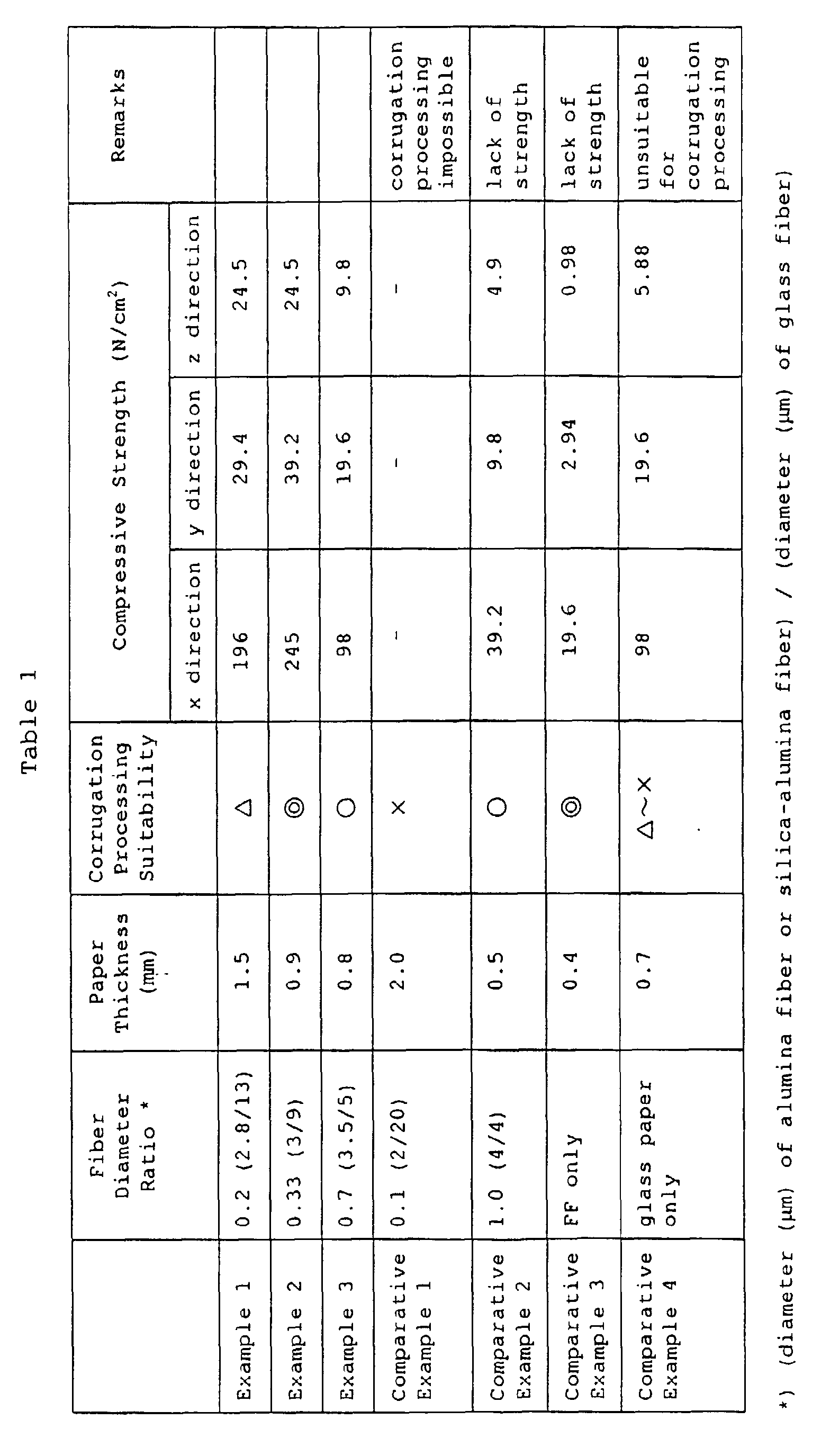
- As shown in Table 1, it can be seen that the paper of the examples obtained by compounding glass fiber and inorganic fiber with a specific diameter ratio can be made thicker than the paper of the comparative examples, and that the paper of the examples has flexibility, and its suitability for corrugation processing is high.
- In addition, the paper of the examples has high compressive strength, and this is presumably due to the fact that the inorganic oxide particles and the inorganic binder permeated the deep portions in large quantities, and that they are held uniformly over the entire paper without being maldistributed.
- As described above, in accordance with the invention, it is possible to obtain a honeycomb structure which excels in the mechanical strength and wear resistance, and which is suitable for a carrier of a catalyst apparatus for exhaust gases which contain a large amount of dust particularly from an oil-fired boiler, a coal-fired boiler, or the like.
- While only certain examples of the invention have been specifically described herein, it will be apparent that numerous modifications may be made thereto without departing from the spirit and scope of the invention.
Claims (8)
- A honeycomb structure comprising:a formed piece obtained by paper formed into a honeycomb shape and including glass fiber and inorganic fiber, the inorganic fiber being other than the glass fiber and proportion of the diameter of the inorganic fiber being 0.2 to 0.7 with respect to the glass fiber,wherein said formed piece is impregnated with inorganic oxide particles and an inorganic binder.
- The honeycomb structure according to claim 1, wherein the inorganic fiber is at least one of silica-alumina fiber and alumina fiber.
- The honeycomb structure according to claim 1, wherein material of the inorganic oxide particles is at least one of alumina, quartzite, and kaolin.
- The honeycomb structure according to claim 1, wherein at least one kind of particles of oxides of titanium, vanadium, tungsten, and molybdenum is jointly used with the inorganic oxide particles.
- A catalyst structure for exhaust gases comprising a honeycomb structure including:a formed piece obtained by paper formed into a honeycomb shape and including glass fiber and inorganic fiber, the inorganic fiber being other than the glass fiber and proportion of the diameter of the inorganic fiber being 0.2 to 0.7 with respect to the glass fiber,wherein said formed piece is impregnated with inorganic oxide particles and an inorganic binder.
- The catalyst structure according to claim 5, wherein the inorganic fiber is at least one of silica-alumina fiber and alumina fiber.
- The catalyst structure according to claim 5, wherein material of the inorganic oxide particles is at least one of alumina, quartzite, and kaolin.
- The honeycomb structure according to claim 5, wherein at least one kind of particles of oxides of titanium, vanadium, tungsten, and molybdenum is jointly used with the inorganic oxide particles.
Applications Claiming Priority (2)
| Application Number | Priority Date | Filing Date | Title |
|---|---|---|---|
| JP32276499A JP2001137713A (en) | 1999-11-12 | 1999-11-12 | Honeycomb structure |
| JP32276499 | 1999-11-12 |
Publications (2)
| Publication Number | Publication Date |
|---|---|
| EP1099834A2 true EP1099834A2 (en) | 2001-05-16 |
| EP1099834A3 EP1099834A3 (en) | 2003-04-02 |
Family
ID=18147392
Family Applications (1)
| Application Number | Title | Priority Date | Filing Date |
|---|---|---|---|
| EP00124658A Withdrawn EP1099834A3 (en) | 1999-11-12 | 2000-11-10 | Honeycomb structure |
Country Status (4)
| Country | Link |
|---|---|
| US (1) | US6524680B1 (en) |
| EP (1) | EP1099834A3 (en) |
| JP (1) | JP2001137713A (en) |
| KR (1) | KR100571226B1 (en) |
Cited By (4)
| Publication number | Priority date | Publication date | Assignee | Title |
|---|---|---|---|---|
| CN103429345A (en) * | 2011-03-10 | 2013-12-04 | 株式会社F.C.C. | Exhaust purification equipment |
| EP2818241A4 (en) * | 2012-02-22 | 2015-11-04 | Hitachi Shipbuilding Eng Co | TREATMENT APPARATUS EQUIPPED WITH CATALYST-SUPPORTED HONEYCOMB STRUCTURE AND METHOD FOR MANUFACTURING THE SAME |
| EP2933020A4 (en) * | 2012-12-17 | 2016-08-17 | Hitachi Shipbuilding Eng Co | TREATMENT DEVICE EQUIPPED WITH CATALYST SUPPORT STRUCTURE OF HONEYCOMB AND METHOD FOR PRODUCING THE SAME |
| EP3524346A4 (en) * | 2016-10-05 | 2020-05-27 | Hitachi Zosen Corporation | CATALYST SUPPORT STRUCTURE AND MANUFACTURING METHOD THEREOF |
Families Citing this family (12)
| Publication number | Priority date | Publication date | Assignee | Title |
|---|---|---|---|---|
| US6787497B2 (en) * | 2000-10-06 | 2004-09-07 | Akzo Nobel N.V. | Chemical product and process |
| RU2286428C2 (en) * | 2005-02-16 | 2006-10-27 | Валериан Маркович Соболев | Heat-insulated building member |
| KR100868958B1 (en) * | 2008-07-24 | 2008-11-17 | 대영케미칼(주) | Improved Selective Catalytic Reduction Catalyst Module for Nitrogen Oxide Removal Method and Stacked Catalyst Module for Selective Catalytic Reduction Reaction |
| CN102748108B (en) * | 2012-07-11 | 2016-12-21 | 中国第一汽车股份有限公司 | The preparation method of the high-strength after-treatment carrier unit of papery |
| CN102748109B (en) * | 2012-07-11 | 2016-03-09 | 中国第一汽车股份有限公司 | The preparation method of the exhaust aftertreatment carrier element of papery |
| CN102720564B (en) * | 2012-07-11 | 2017-04-05 | 中国第一汽车股份有限公司 | The preparation method of high intensity post-treating metal carrier element |
| CN108025291B (en) * | 2015-10-28 | 2021-07-09 | 优美科股份公司及两合公司 | Honeycomb catalyst for removing nitrogen oxides in flue gas and exhaust gas and preparation method thereof |
| PL3426395T3 (en) * | 2016-03-09 | 2023-01-16 | Umicore Ag & Co. Kg | METHOD OF PRODUCING A HONEYCOMB STRUCTURE CATALYST BASED ON A FIBROUS NONWOVEN MATERIAL |
| KR102377622B1 (en) * | 2017-08-24 | 2022-03-24 | 주식회사 엘지화학 | Method preparing for silica aerogel blanket and apparatus preparing for the same |
| WO2019195406A1 (en) | 2018-04-04 | 2019-10-10 | Unifrax | Llc | Activated porous fibers and products including same |
| JP7005455B2 (en) * | 2018-08-31 | 2022-01-21 | 日立造船株式会社 | Gas treatment equipment and its manufacturing method |
| CN112138727A (en) * | 2020-09-24 | 2020-12-29 | 江西博鑫精陶环保科技有限公司 | Inorganic fiber honeycomb carrier and preparation method thereof |
Citations (1)
| Publication number | Priority date | Publication date | Assignee | Title |
|---|---|---|---|---|
| JPH02187147A (en) | 1989-01-14 | 1990-07-23 | Hitachi Zosen Corp | Method for manufacturing denitrification catalyst using ceramic paper |
Family Cites Families (4)
| Publication number | Priority date | Publication date | Assignee | Title |
|---|---|---|---|---|
| US4280926A (en) * | 1978-09-12 | 1981-07-28 | Sakai Chemical Industry Co., Ltd. | Method for producing a catalyst and a carrier therefor |
| US4520124A (en) * | 1981-03-19 | 1985-05-28 | Sakai Chemical Industry Co., Ltd. | Method for producing a catalytic structure for the reduction of nitrogen oxides |
| ATE114494T1 (en) * | 1988-04-08 | 1994-12-15 | Mitsubishi Heavy Ind Ltd | CATALYTIC FILTER, METHOD OF MANUFACTURE OF A CATALYTIC FILTER AND METHOD OF TREATMENT OF COMBUSTION GASES WITH A CATALYTIC FILTER. |
| US5250094A (en) * | 1992-03-16 | 1993-10-05 | Donaldson Company, Inc. | Ceramic filter construction and method |
-
1999
- 1999-11-12 JP JP32276499A patent/JP2001137713A/en active Pending
-
2000
- 2000-11-09 KR KR1020000066300A patent/KR100571226B1/en not_active Expired - Fee Related
- 2000-11-10 EP EP00124658A patent/EP1099834A3/en not_active Withdrawn
- 2000-11-13 US US09/709,301 patent/US6524680B1/en not_active Expired - Lifetime
Patent Citations (1)
| Publication number | Priority date | Publication date | Assignee | Title |
|---|---|---|---|---|
| JPH02187147A (en) | 1989-01-14 | 1990-07-23 | Hitachi Zosen Corp | Method for manufacturing denitrification catalyst using ceramic paper |
Cited By (8)
| Publication number | Priority date | Publication date | Assignee | Title |
|---|---|---|---|---|
| CN103429345A (en) * | 2011-03-10 | 2013-12-04 | 株式会社F.C.C. | Exhaust purification equipment |
| CN103429345B (en) * | 2011-03-10 | 2015-11-25 | 株式会社F.C.C. | Exhaust purification equipment |
| EP2818241A4 (en) * | 2012-02-22 | 2015-11-04 | Hitachi Shipbuilding Eng Co | TREATMENT APPARATUS EQUIPPED WITH CATALYST-SUPPORTED HONEYCOMB STRUCTURE AND METHOD FOR MANUFACTURING THE SAME |
| US10052586B2 (en) | 2012-02-22 | 2018-08-21 | Hitachi Zosen Corporation | Processing apparatus equipped with catalyst-supporting honeycomb structure, and method for manufacturing same |
| US10449493B2 (en) | 2012-02-22 | 2019-10-22 | Hitachi Zosen Corporation | Processing apparatus equipped with catalyst-supporting honeycomb structure, and method for manufacturing same |
| EP2933020A4 (en) * | 2012-12-17 | 2016-08-17 | Hitachi Shipbuilding Eng Co | TREATMENT DEVICE EQUIPPED WITH CATALYST SUPPORT STRUCTURE OF HONEYCOMB AND METHOD FOR PRODUCING THE SAME |
| US10138787B2 (en) | 2012-12-17 | 2018-11-27 | Hitachi Zosen Corporation | Treatment device equipped with catalyst-supporting honeycomb structure, and method for producing same |
| EP3524346A4 (en) * | 2016-10-05 | 2020-05-27 | Hitachi Zosen Corporation | CATALYST SUPPORT STRUCTURE AND MANUFACTURING METHOD THEREOF |
Also Published As
| Publication number | Publication date |
|---|---|
| EP1099834A3 (en) | 2003-04-02 |
| KR20010060275A (en) | 2001-07-06 |
| US6524680B1 (en) | 2003-02-25 |
| KR100571226B1 (en) | 2006-04-13 |
| JP2001137713A (en) | 2001-05-22 |
Similar Documents
| Publication | Publication Date | Title |
|---|---|---|
| US6524680B1 (en) | Honeycomb structure | |
| US4280926A (en) | Method for producing a catalyst and a carrier therefor | |
| EP3426395B1 (en) | Preparation method of a non-woven fibrous material-based honeycomb catalyst | |
| EP1923373B1 (en) | Method for manufacturing honeycomb structured body | |
| JP4216174B2 (en) | COATING MATERIAL, CERAMIC HONEYCOMB STRUCTURE, AND ITS MANUFACTURING METHOD | |
| JPWO2006126278A1 (en) | Honeycomb structure | |
| EP1736220A1 (en) | Honeycomb structured body | |
| JP6663842B2 (en) | Honeycomb structure, exhaust gas purifying catalyst using the same, and method for producing exhaust gas purifying catalyst | |
| JPWO2004106702A1 (en) | Honeycomb structure | |
| WO2005105705A1 (en) | Honeycomb structure and method for producing same | |
| KR102306141B1 (en) | Denitration catalyst and method for producing same | |
| KR102090726B1 (en) | Metal Structure based NOx Removal Catalyst for Selective Catalyst Reduction using Coating Slurry and Method for Manufacturing Same | |
| WO2017029971A1 (en) | Exhaust gas purifying catalyst | |
| JP5401049B2 (en) | Slurry for producing denitration catalyst, method for producing the slurry, method for producing denitration catalyst using the slurry, and denitration catalyst produced by the method | |
| KR101681063B1 (en) | End-treating method for catalyst-carrying honeycomb structure in exhaust gas denitration system | |
| CN102773121A (en) | Catalyst carrier substrate coated with washcoat comprising fibrous material | |
| JPWO2009141883A1 (en) | Honeycomb structure | |
| WO2008035663A1 (en) | Method for production of catalyst and catalyst produced by the method | |
| JPS5811253B2 (en) | Method for producing catalyst or carrier | |
| JP2004041852A (en) | Catalyst carrier and catalyst body | |
| KR102944753B1 (en) | Selective contact reduction suspension | |
| JP5401315B2 (en) | Exhaust gas purification catalyst manufacturing method and exhaust gas purification catalyst | |
| JP3386587B2 (en) | Honeycomb element | |
| JP2008155132A (en) | Method for producing denitration catalyst | |
| KR100771329B1 (en) | Honeycomb structured body |
Legal Events
| Date | Code | Title | Description |
|---|---|---|---|
| PUAI | Public reference made under article 153(3) epc to a published international application that has entered the european phase |
Free format text: ORIGINAL CODE: 0009012 |
|
| AK | Designated contracting states |
Kind code of ref document: A2 Designated state(s): AT BE CH CY DE DK ES FI FR GB GR IE IT LI LU MC NL PT SE TR |
|
| AX | Request for extension of the european patent |
Free format text: AL;LT;LV;MK;RO;SI |
|
| PUAL | Search report despatched |
Free format text: ORIGINAL CODE: 0009013 |
|
| AK | Designated contracting states |
Kind code of ref document: A3 Designated state(s): AT BE CH CY DE DK ES FI FR GB GR IE IT LI LU MC NL PT SE TR Designated state(s): AT BE CH CY DE DK ES FI FR GB GR IE IT LI LU MC NL PT SE TR |
|
| AX | Request for extension of the european patent |
Extension state: AL LT LV MK RO SI |
|
| RIC1 | Information provided on ipc code assigned before grant |
Ipc: 7B 01J 35/04 B Ipc: 7F 01N 7/16 B Ipc: 7F 01N 3/28 A |
|
| 17P | Request for examination filed |
Effective date: 20030522 |
|
| AKX | Designation fees paid |
Designated state(s): DE DK FR GB |
|
| 17Q | First examination report despatched |
Effective date: 20040914 |
|
| RIN1 | Information on inventor provided before grant (corrected) |
Inventor name: OIKAWA, HIDENORI Inventor name: KOIZUMI, MASAHIRO Inventor name: TANAKA, MINORU |
|
| STAA | Information on the status of an ep patent application or granted ep patent |
Free format text: STATUS: THE APPLICATION IS DEEMED TO BE WITHDRAWN |
|
| 18D | Application deemed to be withdrawn |
Effective date: 20150602 |