EP1099633A2 - Method and apparatus for orienting articles - Google Patents
Method and apparatus for orienting articles Download PDFInfo
- Publication number
- EP1099633A2 EP1099633A2 EP00309863A EP00309863A EP1099633A2 EP 1099633 A2 EP1099633 A2 EP 1099633A2 EP 00309863 A EP00309863 A EP 00309863A EP 00309863 A EP00309863 A EP 00309863A EP 1099633 A2 EP1099633 A2 EP 1099633A2
- Authority
- EP
- European Patent Office
- Prior art keywords
- article
- orientation
- pattern
- pack
- data
- Prior art date
- Legal status (The legal status is an assumption and is not a legal conclusion. Google has not performed a legal analysis and makes no representation as to the accuracy of the status listed.)
- Granted
Links
Images




Classifications
-
- B—PERFORMING OPERATIONS; TRANSPORTING
- B65—CONVEYING; PACKING; STORING; HANDLING THIN OR FILAMENTARY MATERIAL
- B65B—MACHINES, APPARATUS OR DEVICES FOR, OR METHODS OF, PACKAGING ARTICLES OR MATERIALS; UNPACKING
- B65B57/00—Automatic control, checking, warning, or safety devices
- B65B57/10—Automatic control, checking, warning, or safety devices responsive to absence, presence, abnormal feed, or misplacement of articles or materials to be packaged
- B65B57/14—Automatic control, checking, warning, or safety devices responsive to absence, presence, abnormal feed, or misplacement of articles or materials to be packaged and operating to control, or stop, the feed of articles or material to be packaged
-
- B—PERFORMING OPERATIONS; TRANSPORTING
- B65—CONVEYING; PACKING; STORING; HANDLING THIN OR FILAMENTARY MATERIAL
- B65B—MACHINES, APPARATUS OR DEVICES FOR, OR METHODS OF, PACKAGING ARTICLES OR MATERIALS; UNPACKING
- B65B35/00—Supplying, feeding, arranging or orientating articles to be packaged
- B65B35/56—Orientating, i.e. changing the attitude of, articles, e.g. of non-uniform cross-section
- B65B35/58—Turning articles by positively-acting means, e.g. to present labelled portions in uppermost position
Definitions
- the invention relates to a method and apparatus for orienting flexible walled articles, for example of the pillow bag type such as snack packs.
- GB-A-1507365 discloses a CCD camera having a linear array of photodiodes which detects articles as they pass underneath so as to determine the orientation of a reference surface on the article relative to a reference direction. This information is communicated to a pick-up device which can then be operated to change the orientation of the article to a desired orientation. This is suitable for handling irregular shaped articles whose reference surface can be easily detected but is not suitable for more regular shaped articles such as rectangular and square shaped articles.
- GB-A-2327929 describes the use of optical sensors for determining the orientation of a pack which can have one of two orientations. It also mentions that a peg may be used to rotate the pack through 90° if necessary. Again, this is unable to achieve any further distinction than between the two possible orientations of the pack.
- EP-A-0613841 describes a simple realignment device in which a CCD camera detects the orientation of vessels being conveyed on a first conveyor so that a robot arm can take those vessels and place them on a second conveyor in a desired orientation.
- the vessels have a shape which is easily detectable and sufficiently unique to enable its orientation to be determined to a satisfactory level.
- a method of orienting a flexible walled article comprises presenting the article to a pattern detector and detecting a pattern on the surface of the article; comparing the detected pattern with each of a number of predetermined patterns representing respective orientations of the article to identify the orientation of the presented article; and, when the identified orientation is not a required orientation, turning the article in a manner dependent on the identified orientation, so that the article takes up the required orientation.
- apparatus for orienting a flexible walled article comprises a pattern detector for detecting a pattern on the surface of an article; means for presenting the article to the pattern detector; a processor for comparing the detected pattern with each of a number of predetermined patterns representing respective orientations of the article to identify the orientation of the presented article; and an orientation system for, if necessary, turning the article in a manner dependent on the identified orientation so that the article takes up a required orientation.
- the pattern over the entire surface of the article facing the pattern detector is determined, for example using a CCD camera. This is then compared with a set of predetermined patterns to determine the orientation of the article.
- each pattern is defined by the appearance of a number of image areas along the presented surface of the article.
- the pattern detected may only be a portion of the overall pattern since it has been found that this is often sufficient to distinguish between the different orientations of the article. This is particularly so if there are only a limited number of possible orientations such as four or eight, which will usually be the case.
- some very simple pattern matching processes particularly for snack packs, which can be performed very quickly enabling fast processing speeds to be achieved of 120 articles per minute or more.
- the appearance of the surface, or each image area respectively is defined by more than one channel of data, each channel representing a different characteristic of the appearance of the surface or image area.
- One or more of these channels can then be used to make a comparison with the corresponding channel of the predetermined pattern. Conveniently, this comparison is achieved by simply determining the difference between the data values of the two sets and summing the differences.
- the comparing step comprises combining the channels into a single channel and then comparing the single channel with each corresponding single channel of each predetermined pattern.
- the orientation system could be provided by a single orientation device which is operable to carry out which ever turning step(s) is required.
- the article could be fed to a robotic device.
- the orientation system may comprise a first orientation device for imparting a 90° lateral rotation to the article, a second orientation device for imparting a 180° side to side rotation to the article, and a third orientation device for imparting a 180° end to end rotation.
- Separating the orientation system into three devices allows the article to be fed through the apparatus substantially continuously by a conveyor or the like.
- the second orientation device preferably comprises a double twisted band which will be utilized with a bypass path so that if a side to side rotation is not required, the article is not fed to the band.
- the third orientation device conveniently comprises an abutment such as one or more fingers which can be selectively positioned in the path of the article and a pushing device for flipping the article over the abutment.
- the invention is particularly applicable to articles of the pillow bag type such as snack packs containing potato chips, hula hoops and the like. These types of packs are typically created by a form-fill sealing machine such as a vertical form-fill sealing machine, for example the Apex packaging machine manufactured by Ishida Co., Ltd.
- the apparatus shown in Figures 1 and 2 comprises a packet conditioning/detecting system 1 which receives snack packs of the pillow bag type from an intermediate bulk store (not shown) from which they are unscrambled into single file and fed continuously via a conveyor 70 in random orientations.
- the conveyor 70 feeds packs against a guide wall 71 which defines a datum 72 along which the packs are fed into the system 1.
- the system 1 comprises a conveyor belt 2 driven by a motor 3 via a drive belt 4 to feed the packs at about 60 m/min.
- Located above the conveyor belt 2 is a set of rollers 5 mounted on a self leveling support 6 which gently squashes a pack 7, as can be seen in Figure 2, while it is fed forward by the conveyor belt 2.
- a microprocessor 9 is connected to a colour/contrast sensor 10A such as a Wenglor FB01 which receives optical signals from a fibre optic cable 11 having an end 10 facing the packs at a sensing position. This cable 11 also carries light from a white light source (not shown) to the sensing position.
- the end 10 of the fibre optic is mounted above a slot defined between a pair of the rollers 5 and will be spaced from the facing surface of a pack 7 as it passes by. This means that the sensor will "see” a diffused image of the pack surface and thus be less susceptible to minor variations in the lateral position and/or surface appearance of the pack.
- the output from the sensor 10A is scanned by the microprocessor 9 at a nominal but variable rate of 1kHz for a nominal but variable duration of 150ms (giving a nominal but variable number of 150 samples).
- Each sample includes three values corresponding to three separate channels, namely blue/green, red/green, and grey (contrast). If the conveyor belt 2 is run at 60m/min, sampling will be once per millimetre.
- These 3 x 150 data values are stored by the microprocessor 9 for subsequent processing.
- the Wenglor FB01 colour/contrast sensor provides 3 0-10V analogue outputs that are linear to the amount of the colour/contrast that the sensor sees. These outputs are fed to an analogue to digital convertor (not shown) controlled by the microprocessor 9).
- the microprocessor 9 can distinguish between a background, when no pack is present at the sensing portion, and a pack present condition. When a pack is detected (step 100, Figure 3), the microprocessor 9 begins to accumulate data from the sensor 10A (step 105).
- the microprocessor 9 determines the orientation of the pack.
- the method of determining the orientation will be described below but essentially the pack can initially have one of eight different orientations: 1. Right way up, right way round; 2. Right way up, turned 90 degrees; 3. Right way up, turned 180 degrees; 4. Right way up, turned 270 degrees; 5. Wrong way up, right way round; 6. Wrong way up, turned 90 degrees; 7. Wrong way up, turned 180 degrees; 8. Wrong way up, turned 270 degrees.
- the microprocessor 9 determines what turning movements are required to bring the pack to a desired final orientation which will be the same for each pack (step 110). To effect this reorientation, three orientation devices 20-22 are provided in sequence downstream of the system 1, the microprocessor 9 being connected to each of these.
- the first orientation device 20 is for turning the pack between a long side leading orientation to a short side leading orientation. In the case of a square pack, these sides would be of equal length of course. If this rotation is required (step 115), the microprocessor 9 activates a peg 30 (step 120) at the side of the orientation device 20 where it is rotated from a rest position parallel with the direction of movement of the pack 7 (not shown) to an active position shown in Figure 2. In the active position, as the pack 7 is fed by a conveyor 31 (driven by a motor 32 via a drive belt 33), the corner of a long side leading edge will engage the peg 30 so that with the conveyor 31 driving the pack, the pack rotates laterally through 90° as shown in Figure 1 to a short side leading orientation.
- the pack is then fed to the second orientation device 21 which comprises an input conveyor belt 40 which can be moved by the microprocessor 9 between three positions 41A-41C so as to act as a diverter and feed a pack 7 to a bypass conveyor 43 driven by a motor 44 via a drive belt 45 when in position 41B, to a double twisted band 46 also driven by the motor 44 when in position 41B, or to a third, reject position for rejecting packs not recognized by the microprocessor 9 when in position 41C. If a side to side rotation or twist is required (step 125) the belt 40 is moved to the position 41B (step 130) and the band 46 imparts a side to side 180° rotation to the pack 7. Following its passage through the band 46, the pack will exit down onto the conveyor belt 43.
- the second orientation device 21 comprises an input conveyor belt 40 which can be moved by the microprocessor 9 between three positions 41A-41C so as to act as a diverter and feed a pack 7 to a bypass conveyor 43 driven by a motor 44 via a drive belt 45 when in
- the pack is then transferred by the conveyor belt 43 to the third orientation device 22 which comprises a set of conveyor belts 50 and interleaved fingers 51 which are reciprocable between a rest position (not shown) in which they lie under the upper run of the belts 50 and a turning position (shown in Figure 2) in which they protrude upwardly in the path of the pack 7 to form an abutment.
- the fingers 51 are moved upwards (step 140) so that the pack 7 is brought into engagement with the fingers 51.
- fingers 51A forming an actuator are then rotated upwards to rotate the pack through 180° in an end to end manner over the fingers 51. (It will be appreciated that the foward movement of the pack will stop for a moment during this process.)
- the pack 7 is then in its desired orientation and is supplied to a final conveyor belt 52 for feeding into a carton.
- the microprocessor 9 includes a memory holding eight sets of master tables (master [0] to master [7]) , each containing three data tables with 150 entries.
- the result of the scan is a read table containing three data tables each with 150 entries, each data table corresponding to one of the three detection channels.
- the master tables are initially set up by passing a sample pack through the packet conditioning system 1 eight times in a predetermined order as for example set out in Table 1 above.
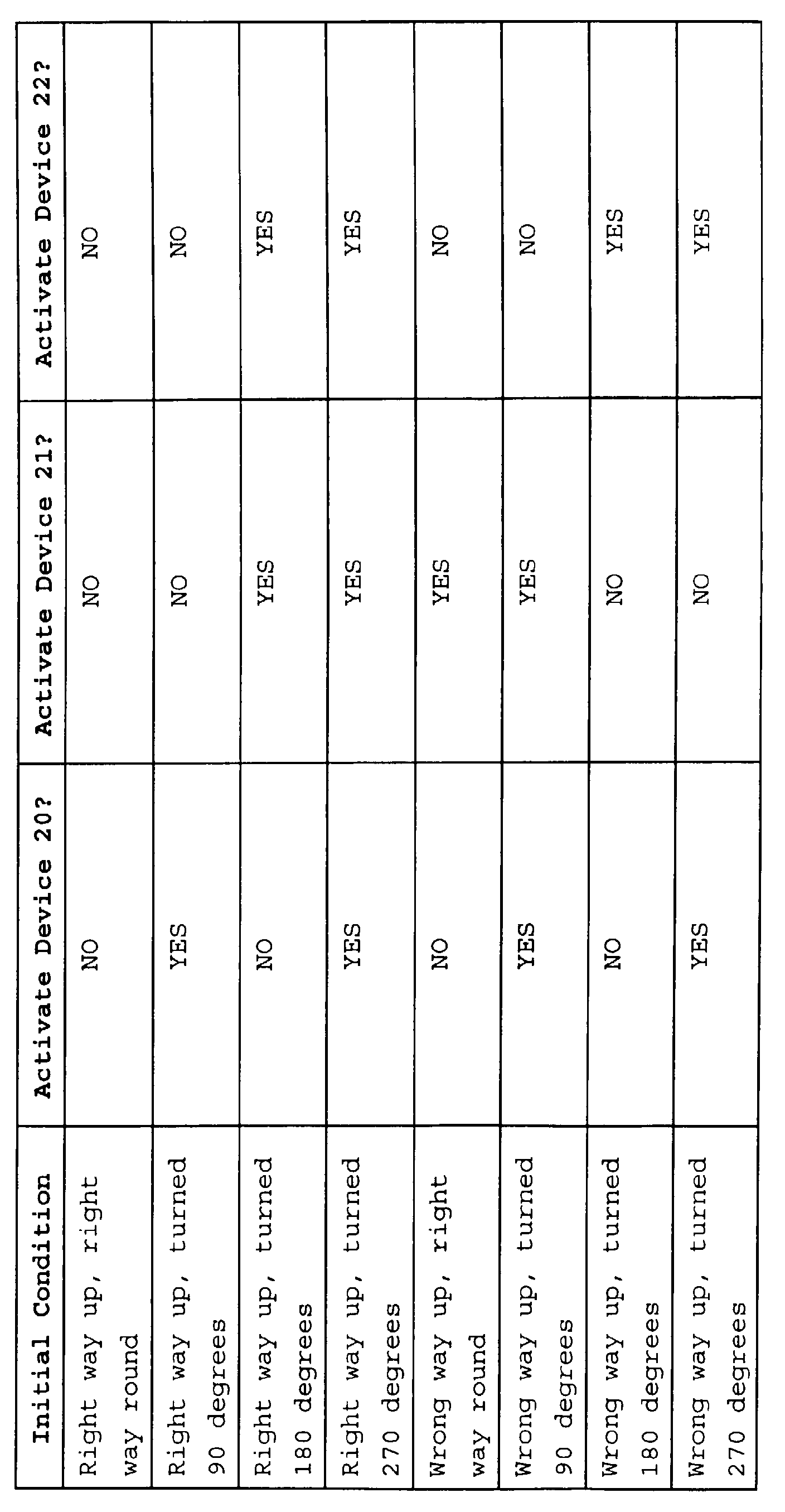
- Table 2 below defines which of the orientation devices 20-22 are activated in each case.
- the microprocessor 9 therefore carries out a time shift compensation before carrying out the pattern analysis described above. This can be achieved, for example, by finding the best match for ten samples of data in a +/- 10ms band in each master pattern in order to find the best time shift. At each offset, the arithmetic difference between the data values of each input pixel and the corresponding data value of the stored master pattern pixel are determined and then these differences summed. The offset corresponding to the lowest sum is chosen for the subsequent comparison process.
- the software may also be desirable for the software to apply an averaging filter to the input data which causes the patterns to be smoothed.
- each rotation was carried out by a separate orientation device 20-22. Modifications will be apparent to a person skilled in the art in which one or more of these rotations are carried out by the same device.
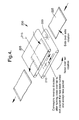
- Figure 4 illustrates a device which can carry out a 180° end to end rotation and a 180° side to side twist.
- an orientation device 200 which replaces the devices 21 and 22 of the previous example.
- the device 200 comprises a pair of upper and lower conveyors 205,210 which can be driven in either direction by a motor and clutch arrangement not shown.
- the conveyors 205,210 are mounted in a support structure (not shown) which can rotate about an axis 215 and an axis 220.
- a pack 225 is fed between the conveyors 210,215, it can then be turned from end to end in the same way as was effected by the device 22 in the previous example or twisted laterally about the axis 220 in the same way as effected by the device 21.
- the conveyors 205,210 will need to be reversed to feed the pack out.
- one or two of the orientation devices 20-22 could simply be omitted. This will be feasible where the output side of the system does not care whether or not an article has a particular orientation in a particular sense.
- Figure 5 illustrates a second, preferred example which is similar to the example of Figures 1 and 2, similar components being indicated by the same reference numerals.
- a packet conditioning/detecting system will be provided but this is omitted for clarity from Figure 5.
- no sensor 10A is provided.
- the system 1 feeds articles such as snack packs to the first orientation device 20' which is identical with the orientation device 20 except for the addition of a sensor 100.
- This sensor 100 is located laterally to one side of the path of the articles so as to detect articles which are being fed with their long edge leading (in the case of rectangular articles).
- the sensor 100 is connected to a microprocessor 110 which responds to a signal from the sensor 100 indicating that an article has been detected to cause the peg 30 to rotate into the path of the article (as shown in Figure 1) so that the article is reoriented with its short edge leading.
- the pack is then fed to a detection stage 115 comprising a conveyor 120 with a CCD camera 125 located above the conveyor.
- This has integral LED lighting panels (not shown).
- An example of a suitable camera is the Keyence CV-501 vision system.
- the camera 125 is connected to the microprocessor 110.
- a device can be located under the camera so as to help to square up packs just before they are viewed by the camera.
- a sensor 130 is positioned relative to the conveyor 120 so as to detect the arrival of a leading edge of a pack and this is used, after a suitable delay to allow the pack to be centred beneath the camera, to trigger the camera 125.
- the camera 125 then takes a photograph of the entire facing surface of the pack (or a portion of the pack surface as appropriate). This image is digitized and fed to the microprocessor 110.
- the microprocessor 110 compares the received image using conventional pattern correlation techniques with four reference images corresponding to the four possible orientations of the pack. These correspond to orientations 1, 3, 5 and 7 in Table 1.
- the microprocessor 110 then makes a YES/NO decision as to whether or not a sufficiently high correlation with each reference pattern has been achieved.
- the conveyor belt 40 is moved to the position 41C and the pack is rejected into a reject bin 135. If the pack has been validly detected then the microprocessor 110 will decide whether to feed the pack to the double twisted band 46 (only shown schematically in Figure 5) or to the by-pass conveyor 43. The pack is then fed to the third orientation device 22 which is identical with the device in Figures 1 and 2 and the microprocessor 110 will selectively control the position of the fingers 51 and 54.
- the conveyor belt 40 is movable between each of three positions 41A-41C. In some cases, this will limit the speed of operation of the system, particularly bearing in mind the time needed to move the conveyor from position 41C to position 41B. In an alternative, preferred approach, therefore, shown in Figure 6, the conveyor 40 is only movable between positions 41A and 41B.
- An additional blower shown schematically at 200 opens to one side of the bypass conveyor 43. When a pack is not recognized, the conveyor 40 is arranged in its position 41A so that the pack is transferred to the bypass conveyor 43 and then the blower 200 is activated to blow the pack of the conveyor 43 into the reject bin 135.
- FIG. 6 illustrates an alternative third orientation device 22' which can be utilized in either the Figure 5 or Figure 1 and 2 examples.
- packs from the second orientation device 21 are fed to a conveyor 210 which conveys them downwardly to a gap 215 across which they free fall onto a further conveyor 220 which corresponds to the conveyor 52 in the Figure 1 example.
- an air knife 225 is activated to blow air across the air gap thus flipping the pack as it drops onto the lower conveyor 220.
- a sensor (not shown) is provided to enable the timing of the actuation of the air knife to be accurately controlled.
Landscapes
- Engineering & Computer Science (AREA)
- Mechanical Engineering (AREA)
- Attitude Control For Articles On Conveyors (AREA)
Abstract
Description
- The invention relates to a method and apparatus for orienting flexible walled articles, for example of the pillow bag type such as snack packs.
- Many food stuffs, particularly snacks, are packaged in flexible walled articles which are then loaded into larger cartons or the like for transportation. Recently, transparent "cartons" have been developed into which the snack packs are loaded for sale as complete cartons. In this case, it is desirable to ensure that each pack is oriented in the same way within the carton both for aesthetic reasons and to enable a purchaser to view at least part of the packs through the wall of the carton. It is also helpful in other applications to ensure that the packs are loaded into cartons in the same orientation for ease of checking that there are no rogue packs of a different type.
- Up until now, this process has been largely manual with a human packer receiving a sequence of packs for manually loading into cartons. Recently, a device was disclosed which can distinguish between a "landscape" or "portrait" orientation of a rectangular pack and then rotate it to a required orientation automatically. However, this overlooks or ignores the fact that a typical rectangular pack will have printing on each side and so can take up more than one portrait or landscape orientation. In particular, packs typically carry markings which differ between the front and back of the pack.
- Various patent specifications describe different techniques for orienting articles. For example, GB-A-1507365 discloses a CCD camera having a linear array of photodiodes which detects articles as they pass underneath so as to determine the orientation of a reference surface on the article relative to a reference direction. This information is communicated to a pick-up device which can then be operated to change the orientation of the article to a desired orientation. This is suitable for handling irregular shaped articles whose reference surface can be easily detected but is not suitable for more regular shaped articles such as rectangular and square shaped articles.
- GB-A-2327929 describes the use of optical sensors for determining the orientation of a pack which can have one of two orientations. It also mentions that a peg may be used to rotate the pack through 90° if necessary. Again, this is unable to achieve any further distinction than between the two possible orientations of the pack.
- EP-A-0613841 describes a simple realignment device in which a CCD camera detects the orientation of vessels being conveyed on a first conveyor so that a robot arm can take those vessels and place them on a second conveyor in a desired orientation. The vessels have a shape which is easily detectable and sufficiently unique to enable its orientation to be determined to a satisfactory level.
- In accordance with a first aspect of the present invention, a method of orienting a flexible walled article comprises presenting the article to a pattern detector and detecting a pattern on the surface of the article; comparing the detected pattern with each of a number of predetermined patterns representing respective orientations of the article to identify the orientation of the presented article; and, when the identified orientation is not a required orientation, turning the article in a manner dependent on the identified orientation, so that the article takes up the required orientation.
- In accordance with a second aspect of the present invention, apparatus for orienting a flexible walled article comprises a pattern detector for detecting a pattern on the surface of an article; means for presenting the article to the pattern detector; a processor for comparing the detected pattern with each of a number of predetermined patterns representing respective orientations of the article to identify the orientation of the presented article; and an orientation system for, if necessary, turning the article in a manner dependent on the identified orientation so that the article takes up a required orientation.
- We have developed a new approach to dealing with this problem by detecting the orientation of a pattern on the article and using this information to control any required turning process. Thus, the invention does not rely simply on detecting the physical orientation (portrait or landscape) of the article but upon the orientation of the pattern. In this way, articles which would appear to prior art systems to have the same orientation, but which in fact are reversed or upside down, can be distinguished.
- Surprisingly, we have found that it is possible to carry out sufficiently accurate pattern recognition despite the fact that the article has flexible walls and thus is not guaranteed to present its surface to the pattern detector in exactly the same way on every occasion.
- A variety of pattern matching techniques can be used. In the preferred approach, the pattern over the entire surface of the article facing the pattern detector is determined, for example using a CCD camera. This is then compared with a set of predetermined patterns to determine the orientation of the article.
- In other approaches, however, each pattern is defined by the appearance of a number of image areas along the presented surface of the article. Thus, the pattern detected may only be a portion of the overall pattern since it has been found that this is often sufficient to distinguish between the different orientations of the article. This is particularly so if there are only a limited number of possible orientations such as four or eight, which will usually be the case. Furthermore, we have developed some very simple pattern matching processes, particularly for snack packs, which can be performed very quickly enabling fast processing speeds to be achieved of 120 articles per minute or more.
- Two primary techniques have been developed for comparing the detected pattern with the predetermined patterns. In the preferred technique, the appearance of the surface, or each image area respectively, is defined by more than one channel of data, each channel representing a different characteristic of the appearance of the surface or image area. One or more of these channels can then be used to make a comparison with the corresponding channel of the predetermined pattern. Conveniently, this comparison is achieved by simply determining the difference between the data values of the two sets and summing the differences.
- In another approach, the comparing step comprises combining the channels into a single channel and then comparing the single channel with each corresponding single channel of each predetermined pattern.
- The orientation system could be provided by a single orientation device which is operable to carry out which ever turning step(s) is required. For example, the article could be fed to a robotic device. Alternatively, however, the orientation system may comprise a first orientation device for imparting a 90° lateral rotation to the article, a second orientation device for imparting a 180° side to side rotation to the article, and a third orientation device for imparting a 180° end to end rotation.
- Separating the orientation system into three devices allows the article to be fed through the apparatus substantially continuously by a conveyor or the like.
- The second orientation device preferably comprises a double twisted band which will be utilized with a bypass path so that if a side to side rotation is not required, the article is not fed to the band. The third orientation device conveniently comprises an abutment such as one or more fingers which can be selectively positioned in the path of the article and a pushing device for flipping the article over the abutment.
- Although, three reorientation capabilities are desirable, in some cases less than three are possible if the number of possible initial orientations is limited or only certain orientations are of concern.
- The invention is particularly applicable to articles of the pillow bag type such as snack packs containing potato chips, hula hoops and the like. These types of packs are typically created by a form-fill sealing machine such as a vertical form-fill sealing machine, for example the Apex packaging machine manufactured by Ishida Co., Ltd.
- Some examples of methods and apparatus according to the invention will now be described with reference to the accompanying drawings, in which:-
- Figure 1 is a plan of a first example of the apparatus;
- Figure 2 is a side view of the apparatus shown in Figure 1;
- Figure 3 is a flow diagram illustrating operation of the apparatus of Figures 1 and 2;
- Figure 4 is a schematic view of a modified form of the apparatus shown in Figures 1 and 2;
- Figure 5 is a schematic side view of a second, preferred example; and,
- Figure 6 illustrates a modification of the Figure 5 example.
-
- The apparatus shown in Figures 1 and 2 comprises a packet conditioning/detecting system 1 which receives snack packs of the pillow bag type from an intermediate bulk store (not shown) from which they are unscrambled into single file and fed continuously via a
conveyor 70 in random orientations. Theconveyor 70 feeds packs against aguide wall 71 which defines adatum 72 along which the packs are fed into the system 1. - The system 1 comprises a
conveyor belt 2 driven by a motor 3 via adrive belt 4 to feed the packs at about 60 m/min. Located above theconveyor belt 2 is a set ofrollers 5 mounted on aself leveling support 6 which gently squashes apack 7, as can be seen in Figure 2, while it is fed forward by theconveyor belt 2. A microprocessor 9 is connected to a colour/contrast sensor 10A such as a Wenglor FB01 which receives optical signals from a fibreoptic cable 11 having anend 10 facing the packs at a sensing position. Thiscable 11 also carries light from a white light source (not shown) to the sensing position. Theend 10 of the fibre optic is mounted above a slot defined between a pair of therollers 5 and will be spaced from the facing surface of apack 7 as it passes by. This means that the sensor will "see" a diffused image of the pack surface and thus be less susceptible to minor variations in the lateral position and/or surface appearance of the pack. - The output from the
sensor 10A is scanned by the microprocessor 9 at a nominal but variable rate of 1kHz for a nominal but variable duration of 150ms (giving a nominal but variable number of 150 samples). Each sample includes three values corresponding to three separate channels, namely blue/green, red/green, and grey (contrast). If theconveyor belt 2 is run at 60m/min, sampling will be once per millimetre. These 3 x 150 data values are stored by the microprocessor 9 for subsequent processing. (The Wenglor FB01 colour/contrast sensor provides 3 0-10V analogue outputs that are linear to the amount of the colour/contrast that the sensor sees. These outputs are fed to an analogue to digital convertor (not shown) controlled by the microprocessor 9). - The microprocessor 9 can distinguish between a background, when no pack is present at the sensing portion, and a pack present condition. When a pack is detected (
step 100, Figure 3), the microprocessor 9 begins to accumulate data from thesensor 10A (step 105). - From the received data, the microprocessor 9 determines the orientation of the pack. The method of determining the orientation will be described below but essentially the pack can initially have one of eight different orientations:
1. Right way up, right way round; 2. Right way up, turned 90 degrees; 3. Right way up, turned 180 degrees; 4. Right way up, turned 270 degrees; 5. Wrong way up, right way round; 6. Wrong way up, turned 90 degrees; 7. Wrong way up, turned 180 degrees; 8. Wrong way up, turned 270 degrees. - Having determined the current orientation, the microprocessor 9 determines what turning movements are required to bring the pack to a desired final orientation which will be the same for each pack (step 110). To effect this reorientation, three orientation devices 20-22 are provided in sequence downstream of the system 1, the microprocessor 9 being connected to each of these.
- The
first orientation device 20 is for turning the pack between a long side leading orientation to a short side leading orientation. In the case of a square pack, these sides would be of equal length of course. If this rotation is required (step 115), the microprocessor 9 activates a peg 30 (step 120) at the side of theorientation device 20 where it is rotated from a rest position parallel with the direction of movement of the pack 7 (not shown) to an active position shown in Figure 2. In the active position, as thepack 7 is fed by a conveyor 31 (driven by amotor 32 via a drive belt 33), the corner of a long side leading edge will engage thepeg 30 so that with theconveyor 31 driving the pack, the pack rotates laterally through 90° as shown in Figure 1 to a short side leading orientation. - The pack is then fed to the
second orientation device 21 which comprises aninput conveyor belt 40 which can be moved by the microprocessor 9 between threepositions 41A-41C so as to act as a diverter and feed apack 7 to abypass conveyor 43 driven by amotor 44 via adrive belt 45 when inposition 41B, to a doubletwisted band 46 also driven by themotor 44 when inposition 41B, or to a third, reject position for rejecting packs not recognized by the microprocessor 9 when inposition 41C. If a side to side rotation or twist is required (step 125) thebelt 40 is moved to theposition 41B (step 130) and theband 46 imparts a side to side 180° rotation to thepack 7. Following its passage through theband 46, the pack will exit down onto theconveyor belt 43. - The pack is then transferred by the
conveyor belt 43 to thethird orientation device 22 which comprises a set ofconveyor belts 50 and interleavedfingers 51 which are reciprocable between a rest position (not shown) in which they lie under the upper run of thebelts 50 and a turning position (shown in Figure 2) in which they protrude upwardly in the path of thepack 7 to form an abutment. If an end to end rotation is required (step 135), thefingers 51 are moved upwards (step 140) so that thepack 7 is brought into engagement with thefingers 51. Further,fingers 51A forming an actuator are then rotated upwards to rotate the pack through 180° in an end to end manner over thefingers 51. (It will be appreciated that the foward movement of the pack will stop for a moment during this process.) Thepack 7 is then in its desired orientation and is supplied to afinal conveyor belt 52 for feeding into a carton. - The microprocessor 9 includes a memory holding eight sets of master tables (master [0] to master [7]) , each containing three data tables with 150 entries. The result of the scan is a read table containing three data tables each with 150 entries, each data table corresponding to one of the three detection channels.
- The master tables are initially set up by passing a sample pack through the packet conditioning system 1 eight times in a predetermined order as for example set out in Table 1 above.
- When a pack to be orientated is passed through the system 1, data values from the sensor are entered into the read tables. As soon as all values have been read, data matching is started. The data matching works as follows:
- 1. Compare data values, from first to last entries,
of the read tables with the same values in the first set of
master tables. Add up the absolute differences (d).
E.g. d=d+abs (read[m] [n] -master[0] [m] [n]) ; //m=0~2,n=0~149
where m is the channel number; and,
n is the sample number - 2. Repeat step 1 for the other master tables (master [1] to master [7]), adding the differences to separate totals.
- 3. Compare the totals. The master table causing the lowest total is deemed to be the closest match, and the software orders the orientation devices to handle the pack as required.
-
- Table 2 below defines which of the orientation devices 20-22 are activated in each case.
- Due to pack variations, the point of detection of the leading edges of the packs may vary slightly. The microprocessor 9 therefore carries out a time shift compensation before carrying out the pattern analysis described above. This can be achieved, for example, by finding the best match for ten samples of data in a +/- 10ms band in each master pattern in order to find the best time shift. At each offset, the arithmetic difference between the data values of each input pixel and the corresponding data value of the stored master pattern pixel are determined and then these differences summed. The offset corresponding to the lowest sum is chosen for the subsequent comparison process.
- In some cases, it may also be desirable for the software to apply an averaging filter to the input data which causes the patterns to be smoothed.
- In the example described in Figures 1 and 2, each rotation was carried out by a separate orientation device 20-22. Modifications will be apparent to a person skilled in the art in which one or more of these rotations are carried out by the same device. Figure 4, for example, illustrates a device which can carry out a 180° end to end rotation and a 180° side to side twist.
- In Figure 4, an
orientation device 200 is shown which replaces thedevices device 200 comprises a pair of upper and lower conveyors 205,210 which can be driven in either direction by a motor and clutch arrangement not shown. The conveyors 205,210 are mounted in a support structure (not shown) which can rotate about anaxis 215 and anaxis 220. Thus, when apack 225 is fed between the conveyors 210,215, it can then be turned from end to end in the same way as was effected by thedevice 22 in the previous example or twisted laterally about theaxis 220 in the same way as effected by thedevice 21. In the case of an end to end rotation about theaxis 215, the conveyors 205,210 will need to be reversed to feed the pack out. - In further modifications, one or two of the orientation devices 20-22 could simply be omitted. This will be feasible where the output side of the system does not care whether or not an article has a particular orientation in a particular sense.
- Figure 5 illustrates a second, preferred example which is similar to the example of Figures 1 and 2, similar components being indicated by the same reference numerals. As in the Figure 1 example, a packet conditioning/detecting system will be provided but this is omitted for clarity from Figure 5. However, in this example, no
sensor 10A is provided. The system 1 feeds articles such as snack packs to the first orientation device 20' which is identical with theorientation device 20 except for the addition of asensor 100. Thissensor 100 is located laterally to one side of the path of the articles so as to detect articles which are being fed with their long edge leading (in the case of rectangular articles). Thesensor 100 is connected to amicroprocessor 110 which responds to a signal from thesensor 100 indicating that an article has been detected to cause thepeg 30 to rotate into the path of the article (as shown in Figure 1) so that the article is reoriented with its short edge leading. - The pack is then fed to a
detection stage 115 comprising aconveyor 120 with aCCD camera 125 located above the conveyor. This has integral LED lighting panels (not shown). An example of a suitable camera is the Keyence CV-501 vision system. Thecamera 125 is connected to themicroprocessor 110. Optionally a device can be located under the camera so as to help to square up packs just before they are viewed by the camera. - A
sensor 130 is positioned relative to theconveyor 120 so as to detect the arrival of a leading edge of a pack and this is used, after a suitable delay to allow the pack to be centred beneath the camera, to trigger thecamera 125. Thecamera 125 then takes a photograph of the entire facing surface of the pack (or a portion of the pack surface as appropriate). This image is digitized and fed to themicroprocessor 110. Themicroprocessor 110 then compares the received image using conventional pattern correlation techniques with four reference images corresponding to the four possible orientations of the pack. These correspond toorientations microprocessor 110 then makes a YES/NO decision as to whether or not a sufficiently high correlation with each reference pattern has been achieved. - If a satisfactory correlation has been made with only one reference pattern then this indicates that the pattern has been successfully read. All other outcomes indicate that the pack has not been successfully read. In the latter case, the
conveyor belt 40 is moved to theposition 41C and the pack is rejected into areject bin 135. If the pack has been validly detected then themicroprocessor 110 will decide whether to feed the pack to the double twisted band 46 (only shown schematically in Figure 5) or to the by-pass conveyor 43. The pack is then fed to thethird orientation device 22 which is identical with the device in Figures 1 and 2 and themicroprocessor 110 will selectively control the position of thefingers 51 and 54. - In the example described above, the
conveyor belt 40 is movable between each of threepositions 41A-41C. In some cases, this will limit the speed of operation of the system, particularly bearing in mind the time needed to move the conveyor fromposition 41C to position 41B. In an alternative, preferred approach, therefore, shown in Figure 6, theconveyor 40 is only movable betweenpositions bypass conveyor 43. When a pack is not recognized, theconveyor 40 is arranged in itsposition 41A so that the pack is transferred to thebypass conveyor 43 and then theblower 200 is activated to blow the pack of theconveyor 43 into thereject bin 135. - This modified approach can also be utilized with the example shown in Figures 1 and 2.
- Previously, the
third orientation device 22 was shown utilizingfingers 51 which could be moved up into the path of a pack so that the packs will be turned end to end. It has been found difficult to achieve that movement quickly enough for fast throughput operation and also the fingers can damage the packs. Figure 6 illustrates an alternative third orientation device 22' which can be utilized in either the Figure 5 or Figure 1 and 2 examples. In this case, packs from thesecond orientation device 21 are fed to aconveyor 210 which conveys them downwardly to agap 215 across which they free fall onto afurther conveyor 220 which corresponds to theconveyor 52 in the Figure 1 example. If a pack has to be turned end to end, anair knife 225 is activated to blow air across the air gap thus flipping the pack as it drops onto thelower conveyor 220. A sensor (not shown) is provided to enable the timing of the actuation of the air knife to be accurately controlled.
Claims (31)
- A method of orienting a flexible walled article, the method comprising presenting the article to a pattern detector and detecting a pattern on the surface of the article; comparing the detected pattern with each of a number of predetermined patterns representing respective orientations of the article to identify the orientation of the presented article; and, when the identified orientation is not a required orientation, turning the article in a manner dependent on the identified orientation, so that the article takes up the required orientation.
- A method according to claim 1, wherein the article is of the pillow bag type.
- A method according to claim 1 or claim 2, wherein the article comprises a snack pack.
- A method according to any of the preceding claims, wherein the article was made by a form fill sealing machine.
- A method according to any of the preceding claims, wherein the detected pattern is compared with four or eight predetermined patterns.
- A method according to any of the preceding claims, wherein the article is presented by moving the article past the pattern detector.
- A method according to any of the preceding claims, wherein each pattern is defined by the appearance of the entire surface of the article presented to the pattern detector.
- A method according to any of claims 1 to 6, wherein each pattern is defined by the appearance of a number of image areas along the presented surface of the article.
- A method according to claim 8, when dependent on claim 6, wherein the image areas are located along a line parallel with the direction of movement of the article.
- A method according to any of claims 7 to 9, wherein the appearance of each pattern is defined by more than one channel of data, each channel representing a different characteristic of the appearance of the image area.
- A method according to claim 10, wherein the data for each channel represents respective colour components or contrast information.
- A method according to claim 10 or claim 11, wherein the comparing step comprises comparing each channel with a corresponding channel of each predetermined pattern.
- A method according to claim 12, wherein the comparing step includes a step of determining the degree of similarity between a predetermined pattern and the detected pattern by determining the difference between the data for each detected pattern or image area of the detected pattern and the corresponding predetermined data for each channel, and summing the differences.
- A method according to claim 13, further comprising comparing the summed difference for each predetermined pattern and identifying the predetermined pattern corresponding to the lowest sum.
- A method according to any of claims 10 to 14, further comprising offsetting the predetermined pattern data relative to the detected pattern data prior to the comparison step so as to temporally align the data sets.
- A method according to claim 15, wherein the offsetting and alignment steps comprise offsetting the predetermined pattern data for at least one channel relative to the corresponding detected pattern data by different amounts, determining the sum of the differences between the two data sets at each offset, and selecting the offset corresponding to the smallest difference sum.
- A method according to any of the preceding claims, wherein the turning step is carried out at spaced locations.
- A method according to any of the preceding claims, wherein the turning step comprises performing one or more of a lateral rotation, an end to end rotation, and a side to side rotation or twist.
- A method according to claim 18, wherein the article is moved substantially continuously past the detector and the turning locations.
- Apparatus for orienting a flexible walled article, the apparatus comprising a pattern detector for detecting a pattern on the surface of an article; means for presenting the article to the pattern detector; a processor for comparing the detected pattern with each of a number of predetermined patterns representing respective orientations of the article to identify the orientation of the presented article; and an orientation system for, if necessary, turning the article in a manner dependent on the identified orientation so that the article takes up a required orientation.
- Apparatus according to claim 20, wherein the orientation system comprises a first orientation device for imparting a 90° lateral rotation to the article.
- Apparatus according to claim 20 or claim 21, wherein the orientation system comprises a second orientation device for imparting a 180° side to side rotation.
- Apparatus according to claim 22, wherein the second orientation device comprises a double twisted band.
- Apparatus according to claim 22 or claim 23, further comprising a bypass path past the second orientation device, and a diverter operable to feed the article either to the second orientation device or to the bypass bath.
- Apparatus according to claim 24, further comprising a blower which is selectively actuable to blow rejected articles off the bypass path.
- Apparatus according to any of claims 20 to 25, wherein the orientation system comprises a third orientation device for imparting a 180° end to end rotation.
- Apparatus according to claim 26, wherein the third orientation device comprises an article conveyor, a selectively operable abutment which can be positioned in the path of the article on the conveyor, and an actuator for lifting the article over the abutment to effect an end to end rotation.
- Apparatus according to claim 26, wherein the third orientation device defines a feed path including a gap across which articles drop in use, and an air knife selectively operable to turn articles as they drop across the gap.
- Apparatus according to claim 21, or any of claims 26 to 28, wherein the first and third devices are selectively operable.
- Apparatus according to any of claims 20 to 29, wherein the pattern detector comprises a CCD camera.
- Apparatus according to any of claims 20 to 30, for carrying out a method according to any of claims 1 to 19.
Applications Claiming Priority (2)
| Application Number | Priority Date | Filing Date | Title |
|---|---|---|---|
| GB9926555 | 1999-11-09 | ||
| GBGB9926555.5A GB9926555D0 (en) | 1999-11-09 | 1999-11-09 | Method and apparatus for orienting flexible walled articles |
Publications (3)
| Publication Number | Publication Date |
|---|---|
| EP1099633A2 true EP1099633A2 (en) | 2001-05-16 |
| EP1099633A3 EP1099633A3 (en) | 2002-04-17 |
| EP1099633B1 EP1099633B1 (en) | 2007-04-25 |
Family
ID=10864241
Family Applications (1)
| Application Number | Title | Priority Date | Filing Date |
|---|---|---|---|
| EP00309863A Expired - Lifetime EP1099633B1 (en) | 1999-11-09 | 2000-11-07 | Method and apparatus for orienting articles |
Country Status (5)
| Country | Link |
|---|---|
| US (1) | US6508351B1 (en) |
| EP (1) | EP1099633B1 (en) |
| JP (1) | JP2001180819A (en) |
| DE (1) | DE60034527T2 (en) |
| GB (1) | GB9926555D0 (en) |
Cited By (4)
| Publication number | Priority date | Publication date | Assignee | Title |
|---|---|---|---|---|
| WO2003018406A1 (en) * | 2001-08-17 | 2003-03-06 | Tetra Laval Holding & Finance S.A. | Device for turning objects |
| WO2003012564A3 (en) * | 2001-07-31 | 2003-08-28 | Schneider Automation | Method and system for packing parts for shipment |
| CN104192551A (en) * | 2014-08-29 | 2014-12-10 | 苏州日月新半导体有限公司 | Material pipe processing device |
| CN104743173A (en) * | 2015-02-14 | 2015-07-01 | 中国科学院合肥物质科学研究院 | Method for controlling packaging bag two-dimension code automatic-recognition transfer belt |
Families Citing this family (16)
| Publication number | Priority date | Publication date | Assignee | Title |
|---|---|---|---|---|
| US6961638B2 (en) * | 2001-12-03 | 2005-11-01 | Oullette Machinery Systems, Inc. | Reject bottle detection and ejection mechanisms |
| DE20307438U1 (en) | 2003-05-12 | 2003-08-28 | GreCon Dimter Holzoptimierung Nord GmbH & Co. KG, 31061 Alfeld | Sorting and separating system for wooden planks of different widths has conveyor removing planks from milling machine and moving planks up against stop before moving to singling device |
| US7111722B2 (en) * | 2004-08-13 | 2006-09-26 | Laitram, L.L.C. | Angled-roller belt conveyor |
| JP5753643B2 (en) * | 2010-04-20 | 2015-07-22 | 株式会社川島製作所 | Cardboard boxing system |
| DE102010043080A1 (en) | 2010-10-28 | 2012-05-03 | Robert Bosch Gmbh | Bag packaging topographical supplying device, has orientation unit determining cause for topographical alignment of bag packaging based on orientation of bag packaging, where orientation of bag packaging is determined by detection unit |
| JP5604496B2 (en) * | 2012-10-24 | 2014-10-08 | 本田技研工業株式会社 | Centering device for plate workpiece |
| DE102013202247A1 (en) | 2013-02-12 | 2014-08-14 | Krones Aktiengesellschaft | Method of fault reporting when grouping articles |
| DE102014206289A1 (en) * | 2014-04-02 | 2015-10-08 | Robert Bosch Gmbh | Hand tool system, method of operation |
| DE102015218389A1 (en) * | 2015-09-24 | 2017-03-30 | Gebr. Willach Gmbh | Conveying device for a goods transfer device of an automatic warehouse |
| CN105460565B (en) * | 2015-12-28 | 2017-12-22 | 青岛汇智智能系统工程有限公司 | A kind of bag body material reason stockline |
| NL2017923B1 (en) * | 2016-12-05 | 2018-06-18 | Qimarox Patenten B V | Device and method configured to control rotation of an object on a carrier |
| CN106515089B (en) * | 2016-12-29 | 2018-10-16 | 温州巨凯机械有限公司 | A kind of paper bag machine bag body synchronization turnover device |
| US11851218B1 (en) * | 2019-09-23 | 2023-12-26 | Amazon Technologies, Inc. | Material handling apparatus |
| US11136726B1 (en) | 2020-06-24 | 2021-10-05 | B & B Metals, Inc. | Tie plate orientation device |
| US12450770B2 (en) | 2021-10-01 | 2025-10-21 | Grupo Bimbo, S.A.B. de CV | Intelligent article orientation |
| US12258158B2 (en) * | 2023-04-20 | 2025-03-25 | Grupo Bimbo S.A.B. De C.V. | Food delivery system for packaging of food and method of delivering food to be packaged |
Citations (2)
| Publication number | Priority date | Publication date | Assignee | Title |
|---|---|---|---|---|
| EP0613841A1 (en) | 1993-03-05 | 1994-09-07 | Shibuya Kogyo Co., Ltd | Apparatus for aligning vessels |
| GB2327929A (en) | 1997-08-01 | 1999-02-10 | Crown Simplimatic Ltd | Singling and orientating apparatus for pillow packs or the like |
Family Cites Families (23)
| Publication number | Priority date | Publication date | Assignee | Title |
|---|---|---|---|---|
| DE1205887B (en) * | 1961-10-12 | 1965-11-25 | Paul Gerhard Klar Dipl Ing | Method and device for the automatic introduction of flat-bag-like packages into collecting containers |
| US3592326A (en) * | 1969-01-31 | 1971-07-13 | Ncr Co | Parcel post singulating and orienting apparatus |
| FR2062683A5 (en) * | 1970-09-25 | 1971-06-25 | Mouton Jean | |
| GB1507365A (en) | 1975-03-20 | 1978-04-12 | Mullard Ltd | Object location detector |
| US4147930A (en) * | 1975-03-20 | 1979-04-03 | U.S. Philips Corporation | Object location detector |
| US4435837A (en) * | 1981-03-05 | 1984-03-06 | President And Fellows Of Harvard College | Pattern recognition and orientation system |
| JPS61150916A (en) * | 1984-12-24 | 1986-07-09 | Citizen Watch Co Ltd | Attitude arrangement device |
| FR2607122B1 (en) | 1986-11-21 | 1989-03-31 | Telemecanique Electrique | PARTS ROUTING LINE FOR AN ORIENTED DISTRIBUTION OF THESE LAST |
| US5204913A (en) * | 1987-09-16 | 1993-04-20 | Juki Corporation | Pattern processing system |
| GB8728486D0 (en) * | 1987-12-04 | 1988-01-13 | Metal Box Plc | Orientation of containers |
| US4907686A (en) | 1988-07-26 | 1990-03-13 | Oak Industries, Inc. | Automatic high speed tie plate reorienting mechanism |
| US4940128A (en) | 1988-11-10 | 1990-07-10 | The Boeing Company | Article orientation system and method |
| US5165219A (en) * | 1990-11-29 | 1992-11-24 | House Food Industrial Co., Ltd. | Packing device for articles that have directionality |
| US5182647A (en) * | 1990-12-13 | 1993-01-26 | Eastman Kodak Company | High resolution charge-coupled device (ccd) camera system |
| JP2927125B2 (en) * | 1992-09-18 | 1999-07-28 | 神鋼電機株式会社 | Parts alignment method |
| JPH06137837A (en) * | 1992-10-23 | 1994-05-20 | Shinko Electric Co Ltd | Part posture determination method in visual posture selection device |
| JPH0743128A (en) * | 1993-07-29 | 1995-02-10 | Ntn Corp | Image processing device for parts feeder |
| SE508007C2 (en) * | 1994-05-20 | 1998-08-10 | Wahlquists Verkstaeder Ab | Device for sorting waste bags |
| JPH0940172A (en) * | 1995-07-24 | 1997-02-10 | Kyoto Seisakusho:Kk | Reverse merging device |
| JP3335517B2 (en) * | 1995-12-25 | 2002-10-21 | ワイケイケイ株式会社 | Article delivery equipment |
| JPH10231018A (en) * | 1997-02-19 | 1998-09-02 | Ishii Ind Co Ltd | Conveyance alignment device |
| GB9719522D0 (en) * | 1997-09-12 | 1997-11-19 | Newman Paul B D | Automated packaging |
| JPH11300670A (en) * | 1998-04-21 | 1999-11-02 | Fanuc Ltd | Article picking-up device |
-
1999
- 1999-11-09 GB GBGB9926555.5A patent/GB9926555D0/en not_active Ceased
-
2000
- 2000-11-06 US US09/705,886 patent/US6508351B1/en not_active Expired - Fee Related
- 2000-11-07 EP EP00309863A patent/EP1099633B1/en not_active Expired - Lifetime
- 2000-11-07 DE DE60034527T patent/DE60034527T2/en not_active Expired - Lifetime
- 2000-11-09 JP JP2000341424A patent/JP2001180819A/en active Pending
Patent Citations (2)
| Publication number | Priority date | Publication date | Assignee | Title |
|---|---|---|---|---|
| EP0613841A1 (en) | 1993-03-05 | 1994-09-07 | Shibuya Kogyo Co., Ltd | Apparatus for aligning vessels |
| GB2327929A (en) | 1997-08-01 | 1999-02-10 | Crown Simplimatic Ltd | Singling and orientating apparatus for pillow packs or the like |
Cited By (5)
| Publication number | Priority date | Publication date | Assignee | Title |
|---|---|---|---|---|
| WO2003012564A3 (en) * | 2001-07-31 | 2003-08-28 | Schneider Automation | Method and system for packing parts for shipment |
| WO2003018406A1 (en) * | 2001-08-17 | 2003-03-06 | Tetra Laval Holding & Finance S.A. | Device for turning objects |
| CN104192551A (en) * | 2014-08-29 | 2014-12-10 | 苏州日月新半导体有限公司 | Material pipe processing device |
| CN104192551B (en) * | 2014-08-29 | 2017-04-19 | 苏州日月新半导体有限公司 | Material pipe processing device |
| CN104743173A (en) * | 2015-02-14 | 2015-07-01 | 中国科学院合肥物质科学研究院 | Method for controlling packaging bag two-dimension code automatic-recognition transfer belt |
Also Published As
| Publication number | Publication date |
|---|---|
| JP2001180819A (en) | 2001-07-03 |
| GB9926555D0 (en) | 2000-01-12 |
| EP1099633A3 (en) | 2002-04-17 |
| EP1099633B1 (en) | 2007-04-25 |
| US6508351B1 (en) | 2003-01-21 |
| DE60034527T2 (en) | 2007-09-13 |
| DE60034527D1 (en) | 2007-06-06 |
Similar Documents
| Publication | Publication Date | Title |
|---|---|---|
| EP1099633B1 (en) | Method and apparatus for orienting articles | |
| KR102048330B1 (en) | A device for feeding items to a sorting machine and sorting machine | |
| US9359150B2 (en) | Singulator | |
| EP1253097B1 (en) | Paper like material processing apparatus | |
| JP2894664B2 (en) | Alignment transfer device for film unit with lens | |
| US8235377B2 (en) | Multi-mode unstacker device for unstacking mailpieces | |
| EP0274000B1 (en) | Method and apparatus for recognizing a gripped condition of linens | |
| US5803702A (en) | Vision inspection system for double stacked packs | |
| JP6761569B2 (en) | Goods sorting device | |
| US6434341B1 (en) | Orientation regularizing apparatus and sorting apparatus for lens-fitted photo film unit | |
| EP0941929B1 (en) | Vision inspection system for double stacked packs | |
| JPH0957213A (en) | Mushroom quality determination device and sorting device | |
| JP2023510878A (en) | Apparatus and method for identifying, measuring and locating discrete items | |
| US20230005127A1 (en) | Method and device for detecting containers which have fallen over and/or are damaged in a container mass flow | |
| JPS6216983A (en) | Collating/packing device for printed sheet | |
| US20250389672A1 (en) | Light directed singulation quality control | |
| US5321929A (en) | Apparatus for positioning articles in boxes or crates | |
| JPH04322778A (en) | Conveyor system for classifier | |
| CA2848444C (en) | Singulator | |
| JP2006122765A (en) | Inspection apparatus for produce | |
| JP2008127114A (en) | Article conveying device | |
| KR100315003B1 (en) | Waste glass bottle color-classification method and apparatus of the same | |
| JPH1191924A (en) | Agricultural product transport device and measuring device using the same | |
| JP3095577B2 (en) | Bottle color recognition method | |
| GB2301787A (en) | Separating and sequencing apparatus |
Legal Events
| Date | Code | Title | Description |
|---|---|---|---|
| PUAI | Public reference made under article 153(3) epc to a published international application that has entered the european phase |
Free format text: ORIGINAL CODE: 0009012 |
|
| AK | Designated contracting states |
Kind code of ref document: A2 Designated state(s): DE FR GB IT Kind code of ref document: A2 Designated state(s): AT BE CH CY DE DK ES FI FR GB GR IE IT LI LU MC NL PT SE TR |
|
| AX | Request for extension of the european patent |
Free format text: AL;LT;LV;MK;RO;SI |
|
| PUAL | Search report despatched |
Free format text: ORIGINAL CODE: 0009013 |
|
| AK | Designated contracting states |
Kind code of ref document: A3 Designated state(s): AT BE CH CY DE DK ES FI FR GB GR IE IT LI LU MC NL PT SE TR |
|
| AX | Request for extension of the european patent |
Free format text: AL;LT;LV;MK;RO;SI |
|
| 17P | Request for examination filed |
Effective date: 20020925 |
|
| AKX | Designation fees paid |
Free format text: DE FR GB IT |
|
| GRAP | Despatch of communication of intention to grant a patent |
Free format text: ORIGINAL CODE: EPIDOSNIGR1 |
|
| RAP1 | Party data changed (applicant data changed or rights of an application transferred) |
Owner name: ISHIDA CO., LTD. |
|
| GRAS | Grant fee paid |
Free format text: ORIGINAL CODE: EPIDOSNIGR3 |
|
| GRAA | (expected) grant |
Free format text: ORIGINAL CODE: 0009210 |
|
| AK | Designated contracting states |
Kind code of ref document: B1 Designated state(s): DE FR GB IT |
|
| REG | Reference to a national code |
Ref country code: GB Ref legal event code: FG4D |
|
| REF | Corresponds to: |
Ref document number: 60034527 Country of ref document: DE Date of ref document: 20070606 Kind code of ref document: P |
|
| ET | Fr: translation filed | ||
| PLBE | No opposition filed within time limit |
Free format text: ORIGINAL CODE: 0009261 |
|
| STAA | Information on the status of an ep patent application or granted ep patent |
Free format text: STATUS: NO OPPOSITION FILED WITHIN TIME LIMIT |
|
| 26N | No opposition filed |
Effective date: 20080128 |
|
| PGFP | Annual fee paid to national office [announced via postgrant information from national office to epo] |
Ref country code: DE Payment date: 20091105 Year of fee payment: 10 |
|
| PGFP | Annual fee paid to national office [announced via postgrant information from national office to epo] |
Ref country code: IT Payment date: 20091114 Year of fee payment: 10 Ref country code: FR Payment date: 20091123 Year of fee payment: 10 Ref country code: GB Payment date: 20091104 Year of fee payment: 10 |
|
| GBPC | Gb: european patent ceased through non-payment of renewal fee |
Effective date: 20101107 |
|
| REG | Reference to a national code |
Ref country code: DE Ref legal event code: R119 Ref document number: 60034527 Country of ref document: DE Effective date: 20110601 Ref country code: DE Ref legal event code: R119 Ref document number: 60034527 Country of ref document: DE Effective date: 20110531 |
|
| REG | Reference to a national code |
Ref country code: FR Ref legal event code: ST Effective date: 20110801 |
|
| PG25 | Lapsed in a contracting state [announced via postgrant information from national office to epo] |
Ref country code: DE Free format text: LAPSE BECAUSE OF NON-PAYMENT OF DUE FEES Effective date: 20110531 |
|
| PG25 | Lapsed in a contracting state [announced via postgrant information from national office to epo] |
Ref country code: FR Free format text: LAPSE BECAUSE OF NON-PAYMENT OF DUE FEES Effective date: 20101130 |
|
| PG25 | Lapsed in a contracting state [announced via postgrant information from national office to epo] |
Ref country code: GB Free format text: LAPSE BECAUSE OF NON-PAYMENT OF DUE FEES Effective date: 20101107 |
|
| PG25 | Lapsed in a contracting state [announced via postgrant information from national office to epo] |
Ref country code: IT Free format text: LAPSE BECAUSE OF NON-PAYMENT OF DUE FEES Effective date: 20101107 |