EP1099577A2 - Vehicle suspension system - Google Patents
Vehicle suspension system Download PDFInfo
- Publication number
- EP1099577A2 EP1099577A2 EP00124759A EP00124759A EP1099577A2 EP 1099577 A2 EP1099577 A2 EP 1099577A2 EP 00124759 A EP00124759 A EP 00124759A EP 00124759 A EP00124759 A EP 00124759A EP 1099577 A2 EP1099577 A2 EP 1099577A2
- Authority
- EP
- European Patent Office
- Prior art keywords
- hydraulic
- cylinders
- hydraulic cylinder
- suspension system
- pressure regulating
- Prior art date
- Legal status (The legal status is an assumption and is not a legal conclusion. Google has not performed a legal analysis and makes no representation as to the accuracy of the status listed.)
- Granted
Links
Images

Classifications
-
- B—PERFORMING OPERATIONS; TRANSPORTING
- B60—VEHICLES IN GENERAL
- B60G—VEHICLE SUSPENSION ARRANGEMENTS
- B60G21/00—Interconnection systems for two or more resiliently-suspended wheels, e.g. for stabilising a vehicle body with respect to acceleration, deceleration or centrifugal forces
- B60G21/02—Interconnection systems for two or more resiliently-suspended wheels, e.g. for stabilising a vehicle body with respect to acceleration, deceleration or centrifugal forces permanently interconnected
- B60G21/06—Interconnection systems for two or more resiliently-suspended wheels, e.g. for stabilising a vehicle body with respect to acceleration, deceleration or centrifugal forces permanently interconnected fluid
-
- B—PERFORMING OPERATIONS; TRANSPORTING
- B60—VEHICLES IN GENERAL
- B60G—VEHICLE SUSPENSION ARRANGEMENTS
- B60G17/00—Resilient suspensions having means for adjusting the spring or vibration-damper characteristics, for regulating the distance between a supporting surface and a sprung part of vehicle or for locking suspension during use to meet varying vehicular or surface conditions, e.g. due to speed or load
- B60G17/02—Spring characteristics, e.g. mechanical springs and mechanical adjusting means
- B60G17/04—Spring characteristics, e.g. mechanical springs and mechanical adjusting means fluid spring characteristics
- B60G17/056—Regulating distributors or valves for hydropneumatic systems
Definitions
- This invention relates to a vehicle suspension system especially for use in automobiles.
- FIG. 5 is a cross-sectional view showing the constitution of a conventional vehicle suspension system.
- the conventional suspension system 1 shown in FIG. 5 is for use in four-wheeled vehicles, and comprises: hydraulic cylinders (oil dampers) 2, 3, 4, and 5 respectively for the left front, right front, left rear, and right rear wheels, and left side and right side pressure regulators 6 and 7.
- the four hydraulic cylinders 2 to 5 have an identical constitution with the interior of a cylinder body 8 filled with working oil and divided with a piston part 9 into an upper and a lower oil chambers 10 and 11.
- the piston part 9 is bored with a communication passage 12 making fluid communication between the upper and the lower oil chambers 10 and 11.
- a throttle 13 is interposed in the communication passage 12.
- hydraulic cylinders 2 to 5 are interposed between a vehicle body side (not shown) and a wheel side (not shown) by connecting the cylinder bodies 8 to the vehicle body side and by pivoting the lower ends of the piston rods 14 to components such as links that move up and down together with wheels relative to the vehicle body.
- the left and right pressure regulators 6 and 7 are also made in an identical constitution.
- Each of the pressure regulators 6 and 7 is constituted by forming two cylinders, a first and a second pressure regulating cylinders 16 and 18, in a single body.
- the first cylinder 16 has a first oil chamber 15 connected to the upper oil chamber 10 of a hydraulic cylinder 2 or 3 for the left or right front wheel.
- the second pressure regulating cylinder 18 has a second oil chamber 17 connected to the upper oil chamber 10 of a hydraulic cylinder 4 or 5 for the left or right rear wheel.
- the oil chambers 15, 17, and a high pressure gas chamber 19 are defined with a free piston 20.
- a throttle 21 is interposed between the first and the second oil chambers 15 and 17.
- the free piston 20 is formed so that the first oil chamber 15 has the same effective cross-sectional area as that of the second oil chamber 17.
- the conventional suspension system 1 constituted as described above produces damping forces with only the throttles 13 of the piston parts 9 when the hydraulic cylinders 2, 3 for the front wheels and the hydraulic cylinders 4, 5 for the rear wheels work in the same direction with an approximately the same operation amount.
- damping forces are produced also with the throttles 21, 21 of the pressure regulators 6 and 7.
- damping forces relatively decrease when the vehicle makes a turn, while damping forces relatively increase when the vehicle makes a panic start or a rapid acceleration.
- the values of a1, a2, S1, S2, ⁇ 1, and ⁇ 2 being set to satisfy the conditions a1 ⁇ a2 and S1/ ⁇ 1 ⁇ S2/ ⁇ 2.
- the vehicle suspension system makes it possible to constitute a front wheel and a rear wheel suspension systems respectively with different specifications while retaining the function of relatively increasing and decreasing the damping forces according to the behavior of the vehicle.
- the working oil is prevented from flowing through the throttles when two wheels move in the same direction by about the same travel, even in the cases of the effective cross-sectional areas a1 and a2 of the pistons of the first and the second hydraulic cylinders being mutually different, and the ratios of the piston travels of the first and the second hydraulic cylinder to the displacement amounts ⁇ 1 and ⁇ 2 of the wheels, or the lever ratios 1/ ⁇ 1 and S2/ ⁇ 2 being mutually different.
- the damping characteristics of the throttles are prevented from changing depending on the direction of working oil flow even in at least one of the cases of; the cross-sectional areas a1 and a2 of the piston rods of the first and second hydraulic cylinders being mutually different, the lever ratios S1/ ⁇ 1 and S2/ ⁇ 2 being mutually different, and the effective cross-sectional areas A1 and A2 of the first and the second pressure regulating cylinders being mutually different.
- the damping characteristics of the throttles are prevented from changing depending on the direction of working oil flow even in at least one of the cases of; the cross-sectional areas a1 and a2 of the piston rods of the first and second hydraulic cylinders being mutually different, the static ground contact loads W1 and W2 of the wheels on the first and the second hydraulic cylinder sides being mutually different, the lever ratios S1/ ⁇ 1 and S2/ ⁇ 2 being mutually different, and the effective cross-sectional areas A1 and A2 of the first and the second pressure regulating cylinders being mutually different.
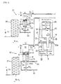
- FIG. 1 is a cross-sectional view showing the constitution of a vehicle suspension system according to the embodiment.
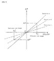
- FIG. 2 is a graph for use in setting the throttles.
- components the same as or similar to those described in reference to FIG. 5 are provided with the same symbols and their detailed descriptions are omitted.
- the embodiment will be described as applied to the front wheel and the rear wheel suspension systems on the left side of a four-wheeled vehicle.
- the front wheel and the rear wheel suspension systems on the other, right side of the vehicle are constituted the same as those shown in FIG. 1.
- a front suspension system 31 and a rear suspension system 32 shown in FIG. 1 are constituted as follows: The one side ends (the right side ends in FIG. 1) of a lower arm 33 and an upper arm 34 are respectively pivoted to a vehicle body. A knuckle 35 supporting a front wheel 36 or a rear wheel 37 for free rotation interconnects the other side ends of the lower and the upper arms 33 and 34. A hydraulic cylinder (hydraulic damper) 2 or 4 is interposed between an intermediate point on the lower arm 33 and the vehicle body. Dimensions of components of the front suspension system 31 and the rear suspension system 32 of this embodiment are set adapt to the vehicle weight distribution.
- the hydraulic cylinder 2 or 4 comprises a piston 100 or 200 comprising a piston part 9 and a piston rod 14. The piston 100 or 200 is inserted for reciprocal movement in a cylinder body 8. The lower end of the piston rod 14 is connected to the lower arm 33 or 34, while the cylinder body 8 is connected to the vehicle body.
- the size of the hydraulic cylinder 8 used in the front suspension system 31 is smaller than the size of the hydraulic cylinder 8 used in the rear suspension system 32. That is to say, the effective cross-sectional area a1 of the piston 100 in the hydraulic cylinder 2 for the front wheel is set to be different from the effective cross-sectional area a2 of the piston 200 in the hydraulic cylinder 4 for the rear wheel.
- the term "effective cross-sectional area” as used herein refers to the cross-sectional area of the portion that affects the amount of the working oil that flows into or out of the hydraulic cylinders 2 and 4. In this embodiment, it refers to the cross-sectional area of the piston rod 14.
- the front wheel suspension system 31 and the rear wheel suspension system 32 are set to be mutually different in the ratio of the wheel travel and the piston travel between the hydraulic cylinders 2 and 4.
- the lever ratio (S1/ ⁇ 1) of the front wheel suspension system 31 is set to be different from the lever ratio (S2/ ⁇ 2) of the rear wheel suspension system 32.
- the hydraulic cylinder 2 for the front wheel corresponds to the first hydraulic cylinder of this invention
- the hydraulic cylinder 4 for the rear wheel corresponds to the second hydraulic cylinder of this invention.
- the left side pressure regulator 6 is constituted with different effective cross-sectional areas A1 and A2 of a first and a second pressure regulating cylinders 16 and 18, respectively connected to the front wheel suspension system 31 and the rear wheel suspension system 32.
- the oil pressure in the (first) oil chamber 15 of the first pressure regulating cylinders 16 is denoted as P1
- the oil pressure in the (second) oil chamber 17 of the second pressure regulating cylinders 18 is denoted as P2
- the pressure in the high pressure gas chamber 19 is denoted as P0.
- the first oil chamber 15 and the second oil chamber 17 are interconnected through a communication passage 40 having a first and a second throttles 38 and 39 interposed in the middle of the passage.
- the first throttle 38 is constituted to permit the working oil to flow only from the first oil chamber 15 to the second oil chamber 17 and to produce a damping force as the working oil flows through it.
- the second throttle 39 is constituted to permit the working oil to flow only from the second oil chamber 17 to the first oil chamber 15 and to produce a damping force as the working oil flows through it.
- the first and the second throttles 38 and 39 are also set to have different damping force characteristics.
- a free piston 20 comprises a piston 20a in the first pressure regulating cylinder 16 and a piston 20b in the second pressure regulating cylinder 18, with the pistons 20a and 20b interconnected through a connecting rod 20c.
- the pistons 20a and 20b correspond to the movable partition wall of the invention.
- the suspension systems and the hydraulic systems are constituted so that the product of the lever ratio of the front suspension system and the ratio of the effective cross-sectional areas of the pressure regulating cylinder 16 to the piston rod 14 of the front suspension system is approximately the same as the product of the lever ratio of the rear suspension system and the ratio of the effective cross-sectional areas of the pressure regulating cylinder 18 to the piston rod 14 of the rear suspension system.
- ⁇ denotes the differential pressure (P1 - P2) between the oil chambers 15 and 17 when the working oil flows from the first pressure regulating cylinder 16 to the second pressure regulating cylinder 18, and ⁇ ' denotes the differential pressure (P1 - P2) between the oil chambers 15 and 17 when the working oil flows from the second pressure regulating cylinder 18 to the first pressure regulating cylinder 16.
- the above equation (2) is derived by: obtaining a first condition under which the damping force produced through the first throttle 38 during rapid deceleration is equal to the damping force produced through the second throttle 39 during rapid acceleration, obtaining a second condition under which the damping force produced through the second throttle 39 during rapid deceleration is equal to the damping force produced through the first throttle 38 during rapid acceleration, and arranging that the two condition are simultaneously satisfied.
- the process of deriving the equation (2) is described below.
- the damping force characteristics of the first and the second throttles 38 and 39 are obtained by applying the values of dQ3/dt obtained with the equation (4) to the graph of FIG. 2.
- FIG. 2 is a graph of damping force characteristics obtained by experiments of three types of existing throttles A, B, and C, respectively represented with a solid line, a dash-and-dotted line, and a dash-and-double-dotted line, with the horizontal axis representing the value of dQ3/dt and the vertical axis indicating the value of change AP in the oil pressure.
- the value of Q3 obtained with the equation (4) is plotted on FIG. 2 and an appropriate throttle is chosen from the three existing throttles A through C.
- the procedure of choosing the throttle will be described the procedure of choosing the throttle.
- the values A1 and A2 on the right side of the equation (4) are determined once the pressure regulator 6 is formed.
- the values dQ1/dt and dQ2/dt are determined once the specifications of the hydraulic cylinders 2 and 4 for the front and the rear wheels and the lever ratios of the front and the rear suspension systems 31 and 32 are determined. Therefore, the dQ3/dt can be obtained from the equation (4).
- the value dQ3/dt is set for example to a value for ordinary running of an ordinary automobile, namely a value for ordinary range of use.
- the value Q3 is calculated by specifying a time to the value dQ3/dt.
- the value Q3 is obtained to correspond to each of the working directions of the hydraulic cylinders 2 and 4.
- the values Q3 corresponding to the working directions are indicated as q3 and q3' in FIG. 2.
- the value ⁇ P in FIG. 2 is obtained from the equation (2) above.
- the value ⁇ can be replaced with ⁇ P, and ⁇ ' can be replaced with ⁇ P'.
- ⁇ P is calculated and put into the transformed equation (2) above to obtain ⁇ P'.
- a throttle is chosen that can provide the ordinary use range q3.
- the throttle A is chosen as the first throttle 38 and throttle B is chosen as the second throttle 39.
- the suspension systems must be constituted also in consideration of the static ground contact loads of the front and the rear wheels 36 and 37.
- An example of constituting the suspension system in consideration of the static ground contact load of the wheel will be described below.
- the static ground contact load of the front wheel 36 is denoted with W1 and that of the rear wheel 37 with W2. Since the constitution of the suspension system of this embodiment is the same as that of the first embodiment, the following description is made in reference to FIGs. 1 and 2.
- ⁇ ⁇ denotes the differential pressure (P1 - P2) between the oil chambers 15 and 17 when the working oil flows from the first pressure regulating cylinder 16 to the second pressure regulating cylinder 18, and ⁇ ' denotes the differential pressure (P1 - P2) between the oil chambers 15 and 17 when the working oil flows from the second pressure regulating cylinder 18 to the first pressure regulating cylinder 16.
- the above equation (2)' is derived by; obtaining a first condition under which the damping force produced through the first throttle 38 during rapid deceleration is equal to the damping force produced through the second throttle 39 during rapid acceleration, obtaining a second condition under which the damping force produced through the second throttle 39 during rapid deceleration is equal to the damping force produced through the first throttle 38 during rapid acceleration, and arranging that the two condition are simultaneously satisfied.
- the process of deriving the equation (2)' is described below.
- the unit inertia mass at the damper of each suspension system is the static ground contact load W1 or W2 multiplied by a certain constant Since the constant is the same at all the dampers, it is neglected for convenience' sake in the following discussion. Therefore, the damping force per unit inertia mass produced through the first throttle 38 during rapid deceleration is assumed to be F1/W1, and the damping force per unit inertia mass produced through the second throttle 39 during rapid acceleration is assumed to be F2'/W2.
- the damping force characteristics of the first and the second throttles 38 and 39 are obtained with the same procedure as that used in the first embodiment. Therefore, the description on the procedure for obtaining the damping force characteristics of the first and the second throttles 38 and 39 is omitted here.
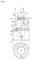
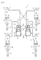
- the pressure regulator may be constituted as shown in FIG. 3 or 4.
- FIGs. 3 and 4 show other example constitutions of the pressure regulator.
- the same or like components as those described in reference to FIGs. 1 and 5 are provided with the same symbols and their detailed descriptions are omitted.
- the pressure regulator 6 shown in FIG. 3 comprises the first pressure regulating cylinder 16 and the second pressure regulating cylinder 18 positioned on the same axial line.
- the pistons 20a and 20b of the free piston 20 are also positioned on the same axial line and interconnected through the connecting rod 20c.
- the piston 20a of the first pressure regulating cylinder 16 is provided with the first and the second throttles 38 and 39.
- the pressure regulator 6 shown in FIG. 4 is constituted with the first pressure regulating cylinder 16 disposed within the piston 20a of the second pressure regulating cylinder 18, and the wall-forming portion of the first pressure regulating cylinder 16 is provided with the first and the second throttles 38 and 39.
- the hydraulic cylinders 2 and 4 for the front and the rear wheels may be formed separately from the hydraulic damper so that these cylinders are connected for interlocked motion with the hydraulic damper.
- the hydraulic cylinders 2 and 4 for the front and the rear wheels may also be formed so that the throttle 13 in the piston part 9 is unnecessary. That is, only one oil chamber is formed in the cylinder body 8, and the oil chamber is connected to the pressure regulator 6.
- the effective cross-sectional areas a1 and a2 of the pistons are the cross-sectional area of the piston part 9.
- Still another possible constitution of the pressure regulator 6 is that the high pressure gas chamber 19 of the first and the second pressure regulating cylinders 16 and 18 is filled with working oil, and the high pressure gas chamber 19 is connected to an oil chamber of another cylinder.
- the another cylinder is constituted that its interior is defined with a free piston into an oil chamber and a high pressure gas chamber, and the oil chamber is connected to the high pressure gas chamber 19 of the pressure regulator 6 filled with working oil.
- the respective paired values of a1 and a2, S1/ ⁇ 1 and S2/ ⁇ 2, or the damping characteristics when the working oil flows from the hydraulic route of the first hydraulic cylinder through the throttle (38) to the hydraulic route of the seconc hydraulic cylinder, and the damping characteristics when the working oil flows from the hydraulic route of the second hydraulic cylinder through the throttle to the hydraulic route of the first hydraulic cylinder, at least one pair of values are set to mutually different values.
- the damping characteristic of the throttle can be prevented from changing depending on the working oil flow direction while constituting one wheel suspension system including the first hydraulic cylinder and the first pressure regulating cylinder differently from the other wheel suspension system including the second hydraulic cylinder and the second pressure regulating cylinder. Therefore, application of this invention to the front wheel and the rear wheel suspension systems makes it possible to increase the degree of freedom of designing the throttle in addition to making it possible to constitute the front wheel and the rear wheel suspension systems respectively compatible with for example vehicle weight distribution while retaining the function of relatively increasing and decreasing damping forces according to the behavior of the vehicle body.
- the damping characteristic of the throttle can be prevented from changing depending on the working oil flow direction even in one of the cases of; the cross-sectional areas a1 and a2 of the piston rods of the first and the second hydraulic cylinders being mutually different, the static ground contact loads W1 and W2 of the wheels on the first and the second hydraulic cylinder sides being mutually different, the lever ratios S1/ ⁇ 1 and S2/ ⁇ 2 being mutually different, and the effective cross-sectional areas A1 and A2 of the first and the second pressure regulating cylinders being mutually different.
Landscapes
- Engineering & Computer Science (AREA)
- Mechanical Engineering (AREA)
- Vehicle Body Suspensions (AREA)
Abstract
Description
- This invention relates to a vehicle suspension system especially for use in automobiles.
- An example of this type of vehicle suspension system is disclosed in a Japanese laid-open patent application No. Hei-8-132846 and is constituted as shown in FIG. 5.
- FIG. 5 is a cross-sectional view showing the constitution of a conventional vehicle suspension system. The
conventional suspension system 1 shown in FIG. 5 is for use in four-wheeled vehicles, and comprises: hydraulic cylinders (oil dampers) 2, 3, 4, and 5 respectively for the left front, right front, left rear, and right rear wheels, and left side and rightside pressure regulators - The four
hydraulic cylinders 2 to 5 have an identical constitution with the interior of acylinder body 8 filled with working oil and divided with apiston part 9 into an upper and alower oil chambers piston part 9 is bored with acommunication passage 12 making fluid communication between the upper and thelower oil chambers throttle 13 is interposed in thecommunication passage 12. - These
hydraulic cylinders 2 to 5 are interposed between a vehicle body side (not shown) and a wheel side (not shown) by connecting thecylinder bodies 8 to the vehicle body side and by pivoting the lower ends of thepiston rods 14 to components such as links that move up and down together with wheels relative to the vehicle body. - The left and
right pressure regulators pressure regulators pressure regulating cylinders first cylinder 16 has afirst oil chamber 15 connected to theupper oil chamber 10 of ahydraulic cylinder pressure regulating cylinder 18 has asecond oil chamber 17 connected to theupper oil chamber 10 of ahydraulic cylinder oil chambers pressure gas chamber 19 are defined with afree piston 20. Athrottle 21 is interposed between the first and thesecond oil chambers free piston 20 is formed so that thefirst oil chamber 15 has the same effective cross-sectional area as that of thesecond oil chamber 17. - The
conventional suspension system 1 constituted as described above produces damping forces with only thethrottles 13 of thepiston parts 9 when thehydraulic cylinders hydraulic cylinders hydraulic cylinders hydraulic cylinders throttles pressure regulators - Also in the prior art, it is arranged in some cases as shown with the phantom lines in FIG. 5, in which the
hydraulic cylinder 2 for the left front wheel and thehydraulic cylinder 5 for the right rear wheel are connected to the rightside pressure regulator 7, and thehydraulic cylinder 3 for the right front wheel and thehydraulic cylinder 4 for the left rear wheel are connected to the leftside pressure regulator 6. When this constitution is employed, the damping forces relatively increase when the vehicle rolls or pitches, and the damping forces relatively decrease when the vehicle bounces. - The conventional
vehicle suspension system 1 constituted as described above, however, must be constituted that every dimension of thehydraulic cylinders 2 to 5, theregulators - Such a problem can be lessened to some extent by mutually changing the constitutions of the front and the rear suspension systems. However, in order to change the constitutions, it must be arranged that the damping forces produced through the throttles do not change between the two cases; one in which the front wheel hydraulic cylinders are compressed while the rear wheel hydraulic cylinders are extended, and the other in which the front wheel hydraulic cylinders are extended while the rear wheel hydraulic cylinders are compressed.
- It is an objective of the present invention to provide a vehicle suspension system having an improved suspension property.
- According to the present invention this objective is solved by a vehicle suspension system according to
claim 1. - Preferably, in the vehicle suspension system the values of a1, a2, S1, S2, λ1, and λ2 being set to satisfy the conditions a1 ≠ a2 and S1/λ1 ≠ S2/λ2.
- Preferably, in the vehicle suspension system the values of a1, a2, S1, S2, λ1, and λ2 being set to satisfy the conditions a1 = a2 and S1/λ1 ≠ S2/λ2 so that the first and the second pressure regulating cylinders (16,18) are constituted to satisfy an equation:
- Preferably in the vehicle suspension system the values of a1, a2, S1, S2, λ1, and λ2 being set to satisfy the conditions a1 ≠ a2 and S1/λ1 = S2/λ2 so that the first and the second hydraulic cylinders (2,4), and the first and the second pressure regulating cylinders (16,18) are constituted to satisfy an equation: (a1/A1) = (a2/A2).
- Preferred embodiments of the present invention are laid down in the dependent claims.
- Advantageously, the vehicle suspension system makes it possible to constitute a front wheel and a rear wheel suspension systems respectively with different specifications while retaining the function of relatively increasing and decreasing the damping forces according to the behavior of the vehicle.
- Accordingly, the vehicle suspension system is constituted with suspension systems, a first and a second hydraulic cylinders, and a first and a second pressure regulating cylinders to satisfy a condition (S1/λ1) x (a1/A1) = (S2/λ2 ) x (a2/A2) on the assumption that;
- S1 and S2 denote piston travels of the first and the second hydraulic cylinders,
- a1 and a2 denote effective cross-sectional areas of pistons of the first and the second hydraulic cylinders,
- λ1 and λ2 denote vertical displacement amounts at ground contact points of wheels caused by the piston travels S1 and S2 of the first and the second hydraulic cylinders, and
- A1 and A2 denote effective cross-sectional areas of the first and the second pressure regulating cylinders,
- with values a1 and a2 of cross-sectional areas of piston rods of the first and the second hydraulic cylinders being set to mutually different values, with lever ratios S1/λ1 and S2/λ2 of the suspension systems being set to mutually different values, and with a1, a2, S1, S2, λ1, and λ2 being set under at least one of conditions a1 ≠ a2 and S1/λ1 = S2/λ2.
-
- With regard thereto, the working oil is prevented from flowing through the throttles when two wheels move in the same direction by about the same travel, even in the cases of the effective cross-sectional areas a1 and a2 of the pistons of the first and the second hydraulic cylinders being mutually different, and the ratios of the piston travels of the first and the second hydraulic cylinder to the displacement amounts λ1 and λ2 of the wheels, or the
lever ratios 1/λ1 and S2/λ2 being mutually different. - Preferably, the vehicle suspension system is constituted with suspension systems, a first and a second hydraulic cylinders, a first and a second pressure regulating cylinders, and throttles are constituted to satisfy an equation
- S1 and S2 denote piston travels of the first and the second hydraulic cylinders,
- a1 and a2 denote effective cross-sectional areas of pistons of the first and the second hydraulic cylinders,
- λ1 and λ2 denote vertical displacement amounts at ground contact points of wheels caused by the piston travels S1 and S2 of the first and the second hydraulic cylinders,
- A1 and A2 denote effective cross-sectional areas of the first and the second pressure regulating cylinders,
- P1 and P2 denote pressures in oil chambers of the first and the second pressure regulating cylinders,
- Δ Φ denotes the differential pressure when working oil flows from the first oil chamber to the second oil chamber, and
- Δ Φ' denotes the differential pressure when working oil flows from the second oil chamber to the first oil chamber, on conditions that,
-
- With regard thereto, the damping characteristics of the throttles are prevented from changing depending on the direction of working oil flow even in at least one of the cases of; the cross-sectional areas a1 and a2 of the piston rods of the first and second hydraulic cylinders being mutually different, the lever ratios S1/λ1 and S2/λ2 being mutually different, and the effective cross-sectional areas A1 and A2 of the first and the second pressure regulating cylinders being mutually different.
- Preferably, the vehicle suspension system is constituted with suspension system, a first and a second hydraulic cylinders, a first and a second pressure regulating cylinders, and throttles are constituted to satisfy an equation
- S1 and S2 denote piston travels of the first and the second hydraulic cylinders,
- a1 and a2 denote effective cross-sectional areas of pistons of the first and the second hydraulic cylinders,
- λ1 and λ2 denote vertical displacement amounts at ground contact points of wheels caused by the piston travels S1 and S2 of the first and the second hydraulic cylinders,
- W1 and W2 denote static ground contact loads of the wheels on the first and the second hydraulic cylinder sides,
- A1 and A2 denote effective cross-sectional areas of the first and the second pressure regulating cylinders,
- P1 and P2 denote pressures in oil chambers of the first and the second pressure regulating cylinders,
- Δ Φ denotes the differential pressure when working oil flows from the first oil chamber to the second oil chamber, and
- Δ Φ' denotes the differential pressure when working oil flows from the second oil chamber to the first oil chamber, on conditions that,
-
- With regard thereto, the damping characteristics of the throttles are prevented from changing depending on the direction of working oil flow even in at least one of the cases of; the cross-sectional areas a1 and a2 of the piston rods of the first and second hydraulic cylinders being mutually different, the static ground contact loads W1 and W2 of the wheels on the first and the second hydraulic cylinder sides being mutually different, the lever ratios S1/λ1 and S2/λ2 being mutually different, and the effective cross-sectional areas A1 and A2 of the first and the second pressure regulating cylinders being mutually different.
- Hereinafter the present invention is illustrated and explained by means of preferred embodiments in conjunction with the accompanying drawings. In the drawings wherein:
- FIG. 1 is a cross-sectional view showing the constitution of a vehicle suspension system according to the embodiment;
- FIG. 2 is a graph for use in setting the throttles;
- FIG. 3 shows an example of another constitution of the pressure regulator;
- FIG. 4 shows an example of still another constitution of the pressure regulator; and
- FIG. 5 is a cross-sectional view showing the constitution of a conventional vehicle suspension system.
-
- The details of a first embodiment will be hereinafter described in reference to FIGs. 1 and 2.
- FIG. 1 is a cross-sectional view showing the constitution of a vehicle suspension system according to the embodiment. FIG. 2 is a graph for use in setting the throttles. In these figures, components the same as or similar to those described in reference to FIG. 5 are provided with the same symbols and their detailed descriptions are omitted. Here, the embodiment will be described as applied to the front wheel and the rear wheel suspension systems on the left side of a four-wheeled vehicle. The front wheel and the rear wheel suspension systems on the other, right side of the vehicle are constituted the same as those shown in FIG. 1.
- A
front suspension system 31 and arear suspension system 32 shown in FIG. 1 are constituted as follows: The one side ends (the right side ends in FIG. 1) of alower arm 33 and anupper arm 34 are respectively pivoted to a vehicle body. Aknuckle 35 supporting afront wheel 36 or arear wheel 37 for free rotation interconnects the other side ends of the lower and theupper arms lower arm 33 and the vehicle body. Dimensions of components of thefront suspension system 31 and therear suspension system 32 of this embodiment are set adapt to the vehicle weight distribution. Thehydraulic cylinder piston piston part 9 and apiston rod 14. Thepiston cylinder body 8. The lower end of thepiston rod 14 is connected to thelower arm cylinder body 8 is connected to the vehicle body. - The size of the
hydraulic cylinder 8 used in thefront suspension system 31 is smaller than the size of thehydraulic cylinder 8 used in therear suspension system 32. That is to say, the effective cross-sectional area a1 of thepiston 100 in thehydraulic cylinder 2 for the front wheel is set to be different from the effective cross-sectional area a2 of thepiston 200 in thehydraulic cylinder 4 for the rear wheel. The term "effective cross-sectional area" as used herein refers to the cross-sectional area of the portion that affects the amount of the working oil that flows into or out of thehydraulic cylinders piston rod 14. Also, the frontwheel suspension system 31 and the rearwheel suspension system 32 are set to be mutually different in the ratio of the wheel travel and the piston travel between thehydraulic cylinders front wheel 36 to be λ1 as the piston of thehydraulic cylinder 2 for thefront wheel 2 travels by a displacement S1 and the vertical displacement at the ground contact point of therear wheel 37 to be λ2 as the piston of thehydraulic cylinder 4 for therear wheel 4 travels by a displacement S2, the lever ratio (S1/λ1) of the frontwheel suspension system 31 is set to be different from the lever ratio (S2/λ2) of the rearwheel suspension system 32. Thehydraulic cylinder 2 for the front wheel corresponds to the first hydraulic cylinder of this invention, and thehydraulic cylinder 4 for the rear wheel corresponds to the second hydraulic cylinder of this invention. - The left
side pressure regulator 6 is constituted with different effective cross-sectional areas A1 and A2 of a first and a secondpressure regulating cylinders wheel suspension system 31 and the rearwheel suspension system 32. The oil pressure in the (first)oil chamber 15 of the firstpressure regulating cylinders 16 is denoted as P1, the oil pressure in the (second)oil chamber 17 of the secondpressure regulating cylinders 18 is denoted as P2, and the pressure in the highpressure gas chamber 19 is denoted as P0. Thefirst oil chamber 15 and thesecond oil chamber 17 are interconnected through acommunication passage 40 having a first and a second throttles 38 and 39 interposed in the middle of the passage. Thefirst throttle 38 is constituted to permit the working oil to flow only from thefirst oil chamber 15 to thesecond oil chamber 17 and to produce a damping force as the working oil flows through it. Thesecond throttle 39 is constituted to permit the working oil to flow only from thesecond oil chamber 17 to thefirst oil chamber 15 and to produce a damping force as the working oil flows through it. The first and the second throttles 38 and 39 are also set to have different damping force characteristics. Afree piston 20 comprises apiston 20a in the firstpressure regulating cylinder 16 and apiston 20b in the secondpressure regulating cylinder 18, with thepistons pistons - Simply changing the constitutions of the suspension systems and the hydraulic systems for the front wheels from those for the rear wheels does not result in agreement in the working oil delivery amounts Q1 and Q2 from the
hydraulic cylinders rear suspension systems hydraulic cylinders pressure regulating cylinders second throttle - The inventor has found out that the unnecessary damping force is prevented from being produced by constituting the suspension systems and the hydraulic systems to satisfy the following equation (1):
- That is to say, the suspension systems and the hydraulic systems are constituted so that the product of the lever ratio of the front suspension system and the ratio of the effective cross-sectional areas of the
pressure regulating cylinder 16 to thepiston rod 14 of the front suspension system is approximately the same as the product of the lever ratio of the rear suspension system and the ratio of the effective cross-sectional areas of thepressure regulating cylinder 18 to thepiston rod 14 of the rear suspension system. Employing the above constitution makes it possible to prevent the unnecessary damping force from being produced as the working oil is prevented from flowing through the first and the second throttles 38 and 39 when the displacement directions and the displacement amounts of the front and therear wheels piston rods hydraulic cylinder 2 for the front wheel and of thehydraulic cylinder 4 for the rear wheel are different from each other, or in the case the ratios of the piston travels S1 and S2 of thehydraulic cylinders - When the
hydraulic cylinder 2 for the front wheel is contracted and thehydraulic cylinder 4 for the rear wheel is extended (as in a panic braking) or on the contrary when thehydraulic cylinder 2 is extended and thehydraulic cylinder 4 is contracted (as in a rapid acceleration), damping forces are produced as the working oil flows through the first and the second throttles 38 and 39. Unless the damping force in the rapid braking is approximately same as the damping force in the rapid acceleration, vertical movement of the vehicle body cannot be controlled appropriately. The inventor has proved that the appropriate control can be realized when the suspension systems and the hydraulic systems (including the first and the second throttles 38 and 39) are constituted to satisfy the following equation (2) when the vehicle body pitches, with thefront wheel 36 and therear wheel 37 displacing in mutually opposite directions by the same displacing speed in absolute value (with d λ1/dt = -d λ2/dt). - In the equation (2), ΔΦ denotes the differential pressure (P1 - P2) between the
oil chambers pressure regulating cylinder 16 to the secondpressure regulating cylinder 18, and ΔΦ' denotes the differential pressure (P1 - P2) between theoil chambers pressure regulating cylinder 18 to the firstpressure regulating cylinder 16. - The above equation (2) is derived by: obtaining a first condition under which the damping force produced through the
first throttle 38 during rapid deceleration is equal to the damping force produced through thesecond throttle 39 during rapid acceleration, obtaining a second condition under which the damping force produced through thesecond throttle 39 during rapid deceleration is equal to the damping force produced through thefirst throttle 38 during rapid acceleration, and arranging that the two condition are simultaneously satisfied. The process of deriving the equation (2) is described below. - When deriving the equation (2), it is assumed that the vertical displacement speeds of the wheels at the ground contact points are the same in absolute value and opposite in direction (with d λ1/dt = - d λ2/dt).
- (a) When it is assumed that F1 is the damping force produced through the
first throttle 38 and F2 is the damping force produced through thesecond throttle 39 in the case thefront wheel 36 moves up relative to the vehicle body and therear wheel 37 moves down relative to the vehicle body during a rapid deceleration for example, namely in the case λ1/dt > 0, λ2/dt < 0, the damping force F1 can be expressed with theequation 1 ○ below, the damping force F2 can be expressed with theequation 2 ○ below, the differential pressure through thepressure regulator 6 can be expressed with theequation 3 ○, and the oil pressure working on thefree piston 20 of thepressure regulator 6 can be expressed with theequation 4 ○.λ1 λ2 ΔP above equations 1 ○, 2 ○ and 4 ○,above equations 2 ○, 3 ○, and 4 ○, - (b) When it is assumed that F1' is the damping force produced through the first
throttle 38 and F2' is the damping force produced through the second throttle 39 in
the case the front wheel 36 moves down relative to the vehicle body and the rear
wheel 37 moves up relative to the vehicle body as during a rapid acceleration,
namely in the case λ1/dt < 0, λ2/dt > 0, the damping force F1' can be expressed with
the equation 1 ○' below, the damping force F2' can be expressed with the equation 2 ○'
below, the differential pressure through the pressure regulator 6 can be expressed
with the equation 3 ○', and the oil pressure working on the free piston 20 of the
pressure regulator 6 can be expressed with the equation 4 ○',
-
- The above-mentioned first condition under which the damping force F1 produced through the
first throttle 38 during rapid deceleration is equal to the damping force F2' produced through thesecond throttle 39 during rapid acceleration is that theequation 5 ○ is equal to 6 ○', namely;
since F1(λ1/dt > 0, λ2/dt < 0) = F2'(λ1/dt < 0, λ2/dt > 0), it is expressed with theequation 7 ○' below: - The second condition under which the damping force F2 produced through the
second throttle 39 during rapid deceleration is equal to the damping force F1' produced through thefirst throttle 39 during rapid acceleration is that theequation 6 ○ is equal to 5 ○', namely;
since F2(λ1/dt > 0, λ2/dt < 0) = F1'(λ1/dt < 0, λ2/dt > 0), it is expressed with theequation 8 ○ below:ΔP - Since the difference between the
equations 7 ○ and 8 ○ is between ΔP and ΔP', which are the differential pressures between the pressure P1 in the first pressure regulating cylinder and the pressure P2 in the second pressure regulating cylinder, ΔP and ΔP', or ΔP' and ΔP, may be replaced with ΔΦ and ΔΦ' for convenience' sake. In this way, the above equation (2) is obtained. - The damping force characteristics of the first and the second throttles 38 and 39 are obtained on the basis of the working oil flow rates through the hydraulic systems respectively connected to the
hydraulic cylinders - The equation (3) can be simplified into the equation (4) below:
- The damping force characteristics of the first and the second throttles 38 and 39 are obtained by applying the values of dQ3/dt obtained with the equation (4) to the graph of FIG. 2.
- FIG. 2 is a graph of damping force characteristics obtained by experiments of three types of existing throttles A, B, and C, respectively represented with a solid line, a dash-and-dotted line, and a dash-and-double-dotted line, with the horizontal axis representing the value of dQ3/dt and the vertical axis indicating the value of change AP in the oil pressure. In this embodiment, the value of Q3 obtained with the equation (4) is plotted on FIG. 2 and an appropriate throttle is chosen from the three existing throttles A through C. Here will be described the procedure of choosing the throttle.
- The values A1 and A2 on the right side of the equation (4) are determined once the
pressure regulator 6 is formed. The values dQ1/dt and dQ2/dt are determined once the specifications of thehydraulic cylinders rear suspension systems hydraulic cylinders - On the other hand, the value ΔP in FIG. 2 is obtained from the equation (2) above. The equation (2) can be expressed as the ratio of ΔΦ to ΔΦ'. That is, since S1/λ1 and a1/A1 on the left side and S2/λ2 and a2/A2 on the right side of the equation (2) are determined by determining the specifications of the
hydraulic cylinders pressure regulator 6, and can be respectively obtained by calculation, assuming K1 to be the calculation result of the left aide and K2 to be that of the right side, the equation (2) can be written in a different form as K1 x ΔΦ = K2 x ΔΦ'. The value ΔΦ can be replaced with ΔP, and ΔΦ' can be replaced with ΔΦP'. Next in FIG. 2, assuming that the throttle A is used in the ordinary use range q3, ΔP is calculated and put into the transformed equation (2) above to obtain ΔP'. By applying the ΔP' to FIG. 2, a throttle is chosen that can provide the ordinary use range q3. In this embodiment, the throttle A is chosen as thefirst throttle 38 and throttle B is chosen as thesecond throttle 39. - As described above, in the
vehicle suspension system 1 of this embodiment, thesuspension systems rear wheels piston rods hydraulic cylinders hydraulic cylinders suspension systems - The
suspension systems rear wheels piston rods 14 of thehydraulic cylinders suspension systems pressure regulating cylinders - Unless the damping force produced with the throttle changes in proportion to the inertia mass of the vehicle body, the oscillation damping effect for the vehicle body decreases undesirably. Therefore, the suspension systems must be constituted also in consideration of the static ground contact loads of the front and the
rear wheels front wheel 36 is denoted with W1 and that of therear wheel 37 with W2. Since the constitution of the suspension system of this embodiment is the same as that of the first embodiment, the following description is made in reference to FIGs. 1 and 2. - Unless the damping forces produced with the first and the second throttles 38 and 39 are approximately the same on the basis of per unit inertia mass expected during rapid deceleration and rapid acceleration, the oscillation of the vehicle body cannot be controlled appropriately. The appropriate control can be realized by constituting the suspension systems and the hydraulic system (including the first and the second throttles 38 and 39) to satisfy the conditions of the following equation (2)' when the vehicle body pitches with the front and the
rear wheels - In the equation (2)', Δ Φ denotes the differential pressure (P1 - P2) between the
oil chambers pressure regulating cylinder 16 to the secondpressure regulating cylinder 18, and ΔΦ' denotes the differential pressure (P1 - P2) between theoil chambers pressure regulating cylinder 18 to the firstpressure regulating cylinder 16. - The above equation (2)' is derived by; obtaining a first condition under which the damping force produced through the
first throttle 38 during rapid deceleration is equal to the damping force produced through thesecond throttle 39 during rapid acceleration, obtaining a second condition under which the damping force produced through thesecond throttle 39 during rapid deceleration is equal to the damping force produced through thefirst throttle 38 during rapid acceleration, and arranging that the two condition are simultaneously satisfied. The process of deriving the equation (2)' is described below. - When deriving the equation (2)', it is assumed that the vertical displacement speeds of the wheels at the ground contact points are the same in absolute value and opposite in direction (with d λ1/dt = - d λ2/dt).
- (a) When it is assumed that F1 is the damping force produced through the
first throttle 38 and F2 is the damping force produced through thesecond throttle 39 in the case thefront wheel 36 moves up relative to the vehicle body and therear wheel 37 moves down relative to the vehicle body as during a rapid deceleration, namely in the case λ1/dt > 0, λ2/dt < 0, the damping force F1 can be expressed with theequation 1 ○ below, the damping force F2 can be expressed with theequation 2 ○ below, the differential pressure through thepressure regulator 6 can be expressed with theequation 3 ○, and the oil pressure working on thefree piston 20 of thepressure regulator 6 can be expressed with theequation 4 ○.λ1 λ2 ΔP above equations 1 ○, 2 ○, and 4 ○,above equations 2 ○, 3 ○, and 4 ○, - (b) When it is assumed that F1' is the damping force produced through the first
throttle 38 and F2' is the damping force produced through the second throttle 39 in
the case the front wheel 36 moves up relative to the vehicle body and the rear wheel
37 moves down relative to the vehicle body as during a rapid acceleration, namely in
the case λ1/dt < 0, λ2/dt > 0, the damping force F1' can be expressed with the
equation 1 ○' below, the damping force F2' can be expressed with the equation 2 ○'
below, the differential pressure through the pressure regulator 6 can be expressed
with the equation 3 ○', and the oil pressure working on the free piston 20 of the
pressure regulator 6 can be expressed with the equation 4 ○',
-
- The unit inertia mass at the damper of each suspension system is the static ground contact load W1 or W2 multiplied by a certain constant Since the constant is the same at all the dampers, it is neglected for convenience' sake in the following discussion. Therefore, the damping force per unit inertia mass produced through the
first throttle 38 during rapid deceleration is assumed to be F1/W1, and the damping force per unit inertia mass produced through thesecond throttle 39 during rapid acceleration is assumed to be F2'/W2. The afore-mentioned first condition (under which the damping force per unit inertia mass F1/W1 produced through thefirst throttle 38 during rapid deceleration is equal to the damping force per unit inertia mass F2'/W2 produced through thesecond throttle 39 during rapid acceleration) can be obtained from the above-describedrelation 5 ○ = 6 ○'. Namely,
since , F1/W1(λ1/dt > 0, λ2/dt < 0) = F2'/W2(λ1/dt < 0, λ2/dt > 0), it can be expressed with thefollowing equation 7 ○:W2 - The second condition under which the damping force per unit inertia mass F2/W2 produced through the
second throttle 39 during rapid deceleration is equal to the damping force per unit inertia mass F1'/W1 produced through thefirst throttle 38 during rapid deceleration can be obtained from the above-describedrelation 6 ○ = 5 ○'. Namely,
since F2/W1(λ1/dt > 0, λ2/dt < 0) = F1'/W1(λ1/dt < 0, λ2/dt > 0), it can be expressed with thefollowing equation 8 ○:W2 - Since the difference between the
equations 7 ○ and 8 ○ is between ΔP and ΔP', which are the differential pressures between the pressure P1 in the first pressure regulating cylinder and the pressure P2 in the second pressure regulating cylinder, ΔP and ΔP', or ΔP' and ΔP, may be replaced with Δ Φ and Δ Φ' for convenience' sake. In this way, the above equation (2)' is obtained. - The damping force characteristics of the first and the second throttles 38 and 39 are obtained with the same procedure as that used in the first embodiment. Therefore, the description on the procedure for obtaining the damping force characteristics of the first and the second throttles 38 and 39 is omitted here.
- In this embodiment, the
suspension systems rear wheels piston rods 14 of thehydraulic cylinders suspension systems pressure regulating cylinders - The pressure regulator may be constituted as shown in FIG. 3 or 4.
- FIGs. 3 and 4 show other example constitutions of the pressure regulator. In these figures, the same or like components as those described in reference to FIGs. 1 and 5 are provided with the same symbols and their detailed descriptions are omitted.
- The
pressure regulator 6 shown in FIG. 3 comprises the firstpressure regulating cylinder 16 and the secondpressure regulating cylinder 18 positioned on the same axial line. Thepistons free piston 20 are also positioned on the same axial line and interconnected through the connecting rod 20c. Thepiston 20a of the firstpressure regulating cylinder 16 is provided with the first and the second throttles 38 and 39. Thepressure regulator 6 shown in FIG. 4 is constituted with the firstpressure regulating cylinder 16 disposed within thepiston 20a of the secondpressure regulating cylinder 18, and the wall-forming portion of the firstpressure regulating cylinder 16 is provided with the first and the second throttles 38 and 39. - Also with the constitution of the
pressure regulator 6 shown in FIG. 3 or 4, the same effect as with the first or the second embodiment is provided. - When one of the above-described first to third embodiments is employed, the
hydraulic cylinders hydraulic cylinders throttle 13 in thepiston part 9 is unnecessary. That is, only one oil chamber is formed in thecylinder body 8, and the oil chamber is connected to thepressure regulator 6. When this constitution is employed, the effective cross-sectional areas a1 and a2 of the pistons are the cross-sectional area of thepiston part 9. - Still another possible constitution of the
pressure regulator 6 is that the highpressure gas chamber 19 of the first and the secondpressure regulating cylinders pressure gas chamber 19 is connected to an oil chamber of another cylinder. The another cylinder is constituted that its interior is defined with a free piston into an oil chamber and a high pressure gas chamber, and the oil chamber is connected to the highpressure gas chamber 19 of thepressure regulator 6 filled with working oil. - Moreover, when the cross-sectional area a1 of the
piston rod 14 of the front wheelhydraulic cylinder 2 is nearly the same as that of thepiston rod 14 of the rear wheelhydraulic cylinder 4, the same effect as with the above embodiments is obtained by determining the lever ratios of the suspension systems and the effective cross-sectional areas A1 and A2 of thepressure regulating cylinders pressure regulator 6 so as to satisfy the following equation (5). - In a similar manner to the above, in the case the lever ratio (S1/λ1) of the front
wheel suspension system 31 is nearly the same as that (S2/λ2) of the rearwheel suspension system 32, the same effect as with the above embodiments is obtained by determining the cross-sectional areas a1 and a2 of thepiston rods 14 and the effective cross-sectional areas A1 and A2 of thepressure regulating cylinders pressure regulator 6 so as to satisfy the following equation (6). - According to the embodiments described above, it is possible to prevent the working oil from flowing through the throttle when both of the front and the rear wheels move in the same direction by a nearly the same travel while constituting one wheel suspension system including the first hydraulic cylinder and the first pressure regulating cylinder differently from the other wheel suspension system including the second hydraulic cylinder and the second pressure regulating cylinder. This makes it possible to increase the degree of freedom in designing the suspension systems. Therefore, application of this invention to the front wheel and the rear wheel suspension systems makes it possible to constitute the front wheel and the rear wheel suspension systems respectively compatible with for example vehicle weight distribution while retaining the function of relatively increasing and decreasing damping forces according to the behavior of the vehicle body.
- A vehicle suspension system is preferably provided with the first oil chamber and the second oil chamber being interconnected by a hydraulic route comprising throttles, and the first and the second hydraulic cylinders, the first and the second pressure regulating cylinders (16,18), and throttles are constituted to satisfy an equation:
(S1/λ1) x (a1/A1) x ΔΦ = (S2/λ2) x (a2/A2) x ΔΦ' wherein Δ Φ denotes a differential pressure when working oil flows from the first oil chamber to the second oil chamber, an Δ Φ' denotes a differential pressure when working oil flows from the second oil chamber to the first oil chamber. - In said vehicle suspension system the respective paired values of a1 and a2, S1/λ1 and S2/λ2, or the damping characteristics when the working oil flows from the hydraulic route of the first hydraulic cylinder through the throttle (38) to the hydraulic route of the seconc hydraulic cylinder, and the damping characteristics when the working oil flows from the hydraulic route of the second hydraulic cylinder through the throttle to the hydraulic route of the first hydraulic cylinder, at least one pair of values are set to mutually different values.
- With regard thereto, the damping characteristic of the throttle can be prevented from changing depending on the working oil flow direction while constituting one wheel suspension system including the first hydraulic cylinder and the first pressure regulating cylinder differently from the other wheel suspension system including the second hydraulic cylinder and the second pressure regulating cylinder. Therefore, application of this invention to the front wheel and the rear wheel suspension systems makes it possible to increase the degree of freedom of designing the throttle in addition to making it possible to constitute the front wheel and the rear wheel suspension systems respectively compatible with for example vehicle weight distribution while retaining the function of relatively increasing and decreasing damping forces according to the behavior of the vehicle body.
- A vehicle suspension system is preferably provided with the first and the second hydraulic cylinders (2,4), the first and the second pressure regulating cylinders (16,18), and throttles are constituted to satisfy an equation:
- In said vehicle suspension system the respective paired values of; a1 and a2, W1 and W2, S1/λ1 and S2/λ12, or the damping characteristics when the working oil flows from the hydraulic route of the first hydraulic cylinder (2) through the throttle (38) to the hydraulic route of the second hydraulic cylinder (4), and the damping characteristics when the working oil flows from the hydraulic route of the second hydraulic cylinder (4) through the throttle (39) to the hydraulic route of the first hydraulic cylinder (2), at least one pair of values are set to mutually different values.
- With regard thereto, the damping characteristic of the throttle can be prevented from changing depending on the working oil flow direction even in one of the cases of; the cross-sectional areas a1 and a2 of the piston rods of the first and the second hydraulic cylinders being mutually different, the static ground contact loads W1 and W2 of the wheels on the first and the second hydraulic cylinder sides being mutually different, the lever ratios S1/λ1 and S2/λ2 being mutually different, and the effective cross-sectional areas A1 and A2 of the first and the second pressure regulating cylinders being mutually different. Therefore, application of this invention to the front wheel and the rear wheel suspension systems makes it possible to increase the degree of freedom of designing the throttle in addition to making it possible to constitute the front wheel and the rear wheel suspension systems respectively compatible with for example vehicle weight distribution while retaining the function of relatively increasing and decreasing damping forces according to the behavior of the vehicle body.
- The above mentioned equations can be adapted to the conditions in that the lever ratio (S1/λ1) of the front
wheel suspension system 31 is nearly the same as that (S2/λ2) of the rearwheel suspension system 32 or in that the cross-sectional area a1 of thepiston rod 14 of the front wheelhydraulic cylinder 2 is nearly the same as that of thepiston rod 14 of the rear wheelhydraulic cylinder 4 as known from the respective specific embodiments. - Regarding the embodiments it is enabled to constitute of a front wheel suspension system and a rear wheel suspension system of respectively different specifications while retaining the function of relatively increasing and decreasing damping forces according to the behavior of a vehicle. The
suspension systems hydraulic cylinders pressure regulating cylinders hydraulic cylinders piston rods 14 of thehydraulic cylinders hydraulic cylinders pressure regulating cylinders
of the respective paired values of; a1 and a2, S1/λ1 and S2/λ2, or the damping characteristics when the working oil flows from the hydraulic route of the first hydraulic cylinder through the throttle to the hydraulic route of the second hydraulic cylinder, and the damping characteristics when the working oil flows from the hydraulic route of the second hydraulic cylinder through the throttle to the hydraulic route of the first hydraulic cylinder, at least one pair of values are set to mutually different values, and when
paired wheels move in mutually opposite directions with the same absolute values of moving speed.
of the respective paired values of; a1 and a2, W1 and W2, S1/λ1 and S2/λ12, or the damping characteristics when the working oil flows from the hydraulic route of the first hydraulic cylinder through the throttle to the hydraulic route of the second hydraulic cylinder, and the damping characteristics when the working oil flows from the hydraulic route of the second hydraulic cylinder through the throttle to the hydraulic route of the first hydraulic cylinder, at least one pair of values are set to mutually different values, and when paired wheels move in mutually opposite directions with the same absolute values of moving speed.
Claims (8)
- A vehicle suspension system comprising:a first and a second hydraulic cylinders (2,4), arranged on a vehicle body, in each hydraulic cylinder (2,4) a piston (100,200) is free reciprocal moveable inserted, each hydraulic cylinder (2,4) is connected to one of wheel side and vehicle body side, and each piston (100,200) is connected to the other of wheel side and vehicle body side;a first pressure regulating cylinder (16) having a first oil chamber (15) connected through a first hydraulic passage to the first hydraulic cylinder (2) and a movable first partition wall (20a) for changing a volume of the first oil chamber, anda second pressure regulating cylinder (18) having a second oil chamber (17) connected through a second hydraulic passage to the second hydraulic cylinder (4) and a movable second partition wall (20b) for changing a volume of the second oil chamber (17), the first and second partition walls (20a,20b) of the first and second pressure regulating cylinders (16,18) being interconnected for interlocked movement, the first hydraulic cylinder (2) and the second hydraulic cylinder (4) are connected by a hydraulic route, whereinthe first and the second hydraulic cylinders (2,4), and the first and the second pressure regulating cylinders (16,18) are constituted to satisfy an equation: (S1/λ1) x (a1/A1) (S2/λ2 ) x (a2/A2), whereinS1 and S2 denote piston travels of the first and the second hydraulic cylinders (2,4),a1 and a2 denote effective cross-sectional areas of the pistons (100,200) of the first and the second hydraulic cylinders (2,4),λ1 and λ2 denote vertical displacement amounts at ground contact points of wheels caused by the piston travels S1 and S2 of the first and the second hydraulic cylinders (2,4), andA1 and A2 denote effective cross-sectional areas of the first and the second pressure regulating cylinders (16,18).
- A vehicle suspension system according to claim 1, characterized in that the values of a1, a2, S1, S2, λ1, and λ2 being set to satisfy the conditions a1 ≠ a2 and S1/λ1 ≠ S2/λ2.
- A vehicle suspension system according to claim 1, characterized in that the values of a1, a2, S1, S2, λ1, and λ2 being set to satisfy the conditions a1 = a2 and S1/λ1 ≠ S2/λ2 so that the first and the second pressure regulating cylinders (16,18) are constituted to satisfy an equation:
- A vehicle suspension system according to claim 1, characterized in that the values of a1, a2, S1, S2, λ1, and λ2 being set to satisfy the conditions a1 ≠ a2 and S1/λ1 = S2/λ2 so that the first and the second hydraulic cylinders (2,4), and the first and the second pressure regulating cylinders (16,18) are constituted to satisfy an equation: (a1/A1) = (a2/A2).
- A vehicle suspension system according to one of the claims 1 to 4 characterized in that the first oil chamber (15) and the second oil chamber (17) are interconnected by a hydraulic route comprising throttles (38,39), and the first and the second hydraulic cylinders (2,4), the first and the second pressure regulating cylinders (16,18), and throttles are constituted to satisfy an equation:Δ Φ denotes a differential pressure when working oil flows from the first oil chamber (15) to the second oil chamber (17), andΔ Φ' denotes a differential pressure when working oil flows from the second oil chamber (17) to the first oil chamber (15).
- A vehicle suspension system according to claim 5 characterized in that the respective paired values of a1 and a2, S1/λ1 and S2/λ2, or the damping characteristics when the working oil flows from the hydraulic route of the first hydraulic cylinder (2) through the throttle (38) to the hydraulic route of the second hydraulic cylinder (4), and the damping characteristics when the working oil flows from the hydraulic route of the second hydraulic cylinder (4) through the throttle (39) to the hydraulic route of the first hydraulic cylinder (2), at least one pair of values are set to mutually different values.
- A vehicle suspension system according to claim 5 or 6, characterized in that the first and the second hydraulic cylinders (2,4), the first and the second pressure regulating cylinders (16,18), and throttles are constituted to satisfy an equation:
- A vehicle suspension system according to claim 7, characterized in that the respective paired values of; a1 and a2, W1 and W2, S1/λ1 and S2/λ12, or the damping characteristics when the working oil flows from the hydraulic route of the first hydraulic cylinder (2) through the throttle (38) to the hydraulic route of the second hydraulic cylinder (4), and the damping characteristics when the working oil flows from the hydraulic route of the second hydraulic cylinder (4) through the throttle (39) to the hydraulic route of the first hydraulic cylinder (2), at least one pair of values are set to mutually different values.
Applications Claiming Priority (4)
| Application Number | Priority Date | Filing Date | Title |
|---|---|---|---|
| JP32086499 | 1999-11-11 | ||
| JP32086499 | 1999-11-11 | ||
| JP2000003385A JP4319309B2 (en) | 1999-11-11 | 2000-01-12 | Vehicle suspension system |
| JP2000003385 | 2000-01-12 |
Publications (3)
| Publication Number | Publication Date |
|---|---|
| EP1099577A2 true EP1099577A2 (en) | 2001-05-16 |
| EP1099577A3 EP1099577A3 (en) | 2001-12-19 |
| EP1099577B1 EP1099577B1 (en) | 2004-09-15 |
Family
ID=26570240
Family Applications (1)
| Application Number | Title | Priority Date | Filing Date |
|---|---|---|---|
| EP00124759A Expired - Lifetime EP1099577B1 (en) | 1999-11-11 | 2000-11-13 | Vehicle suspension system |
Country Status (6)
| Country | Link |
|---|---|
| US (1) | US6556907B1 (en) |
| EP (1) | EP1099577B1 (en) |
| JP (1) | JP4319309B2 (en) |
| AT (1) | ATE276115T1 (en) |
| DE (1) | DE60013732T2 (en) |
| ES (1) | ES2228381T3 (en) |
Cited By (5)
| Publication number | Priority date | Publication date | Assignee | Title |
|---|---|---|---|---|
| EP1213218A3 (en) * | 2000-12-06 | 2003-08-13 | Yamaha Hatsudoki Kabushiki Kaisha | Suspension device for two-wheeled vehicle |
| ES2212860A1 (en) * | 2000-07-12 | 2004-08-01 | Jose Luis Gilsanz Mayor | HYDRAULIC DEVICE FOR THE IMPLEMENTATION OF CALCULATION, BALANCE AND CONTROL SYSTEMS. |
| ES2229893A1 (en) * | 2003-05-09 | 2005-04-16 | Creuat, S.L. | Complementary suspension device |
| DE10349655A1 (en) * | 2003-10-24 | 2005-06-02 | Audi Ag | Hydraulic spring with stabilizer function for axle of road vehicle has two cross-connected hydraulic units with large lower chambers and small upper chambers and air spaces above upper pistons |
| WO2013117777A1 (en) * | 2012-02-09 | 2013-08-15 | Fundacion Tekniker | Suspension system for a vehicle |
Families Citing this family (22)
| Publication number | Priority date | Publication date | Assignee | Title |
|---|---|---|---|---|
| ES2282098T3 (en) * | 1999-04-12 | 2007-10-16 | Kinetic Pty. Ltd. | PASSIVE RUNNING CONTROL FOR A VEHICLE SUSPENSION SYSTEM. |
| JP2001191778A (en) * | 2000-01-11 | 2001-07-17 | Yamaha Motor Co Ltd | Suspension system for automobiles |
| WO2002045982A1 (en) * | 2000-12-07 | 2002-06-13 | Visteon Global Technologies, Inc. | Suspension system for a vehicle |
| GB0104491D0 (en) * | 2001-02-22 | 2001-04-11 | Rolls Royce & Bentley Motor Ca | A vehicle suspension |
| DE10120918B4 (en) * | 2001-04-27 | 2011-05-05 | Continental Aktiengesellschaft | Electrically adjustable, semi-active damper control |
| JP4181768B2 (en) | 2001-11-14 | 2008-11-19 | トヨタ自動車株式会社 | Vehicle suspension system |
| US7571787B2 (en) | 2005-09-30 | 2009-08-11 | Harley-Davidson Motor Company Group, LLC | Headlight mounting arrangement |
| WO2007041095A2 (en) | 2005-09-30 | 2007-04-12 | Harley-Davidson Motor Company Group, Inc. | Leaning suspension mechanics |
| WO2007056685A2 (en) * | 2005-11-04 | 2007-05-18 | Wm. Wrigley Jr. Company | Apparatus for producing a center-filled confectionery and method |
| US7340334B2 (en) * | 2006-06-07 | 2008-03-04 | Honda Motor Co., Ltd. | Control device of variable damping force damper |
| US7946163B2 (en) | 2007-04-02 | 2011-05-24 | Penske Racing Shocks | Methods and apparatus for developing a vehicle suspension |
| CA2608825A1 (en) * | 2007-10-26 | 2009-04-26 | Multimatic Inc. | In wheel suspension system |
| US8403115B2 (en) * | 2008-01-11 | 2013-03-26 | Penske Racing Shocks | Dual rate gas spring shock absorber |
| US8534687B2 (en) | 2010-07-05 | 2013-09-17 | Fluid Ride Ltd. | Suspension strut for a vehicle |
| DE102010036756A1 (en) * | 2010-07-30 | 2012-02-02 | Claas Selbstfahrende Erntemaschinen Gmbh | Self-propelled harvester |
| US8714321B2 (en) * | 2011-06-06 | 2014-05-06 | Douglas Hunter Powell | Long travel shock absorber |
| US8434771B2 (en) | 2011-06-14 | 2013-05-07 | Honda Motor Co., Ltd. | Piston-type actuator and static fluid damper and vehicles including same |
| US9574582B2 (en) | 2012-04-23 | 2017-02-21 | Fluid Ride, Ltd. | Hydraulic pump system and method of operation |
| US9421840B1 (en) * | 2015-05-04 | 2016-08-23 | Motive Power Industry Co., Ltd. | Suspension mechanism |
| WO2019230550A1 (en) * | 2018-05-29 | 2019-12-05 | 日立オートモティブシステムズ株式会社 | Suspension apparatus |
| US12263709B2 (en) * | 2018-10-12 | 2025-04-01 | Hitachi Astemo, Ltd. | Vehicle suspension control device including a damping force adjustable shock absorber |
| CN114364549A (en) * | 2019-05-22 | 2022-04-15 | 马里奥·罗兰多·纳瓦雷特 | land vehicle |
Citations (1)
| Publication number | Priority date | Publication date | Assignee | Title |
|---|---|---|---|---|
| JPH08132846A (en) | 1994-08-05 | 1996-05-28 | Yamaha Motor Co Ltd | Suspension device for four-wheeled vehicle |
Family Cites Families (20)
| Publication number | Priority date | Publication date | Assignee | Title |
|---|---|---|---|---|
| GB2025863B (en) | 1978-06-08 | 1982-07-14 | Alfa Romeo Spa | Vehicle suspension systems |
| IT1179986B (en) | 1984-02-23 | 1987-09-23 | Cometto Ind Spa | HYDRAULIC SYSTEM AND DEVICE FOR THE ISOSTATIC COMPENSATION OF THE SUPPORT REACTIONS OF FRAMES, PARTICULARLY OF TRAILED OR SELF-PROPELLED VEHICLES EQUIPPED WITH FOUR INDEPENDENT HYDRAULIC SUSPENSIONS OR FOUR INDEPENDENT GROUP OF HYDRAULIC SUSPENSIONS |
| US5269556A (en) | 1989-09-29 | 1993-12-14 | Towerhill Holdings Pty. Ltd. | Vehicle suspension including fluid communication circuit and accumulators |
| JP3009756B2 (en) | 1991-05-02 | 2000-02-14 | トヨタ自動車株式会社 | Hydraulic active suspension |
| JP2924306B2 (en) | 1991-06-03 | 1999-07-26 | 日産自動車株式会社 | Wheel independent suspension |
| CA2112671A1 (en) | 1991-07-02 | 1993-01-21 | Christopher B. Heyring | Vehicle suspension system |
| JPH05213040A (en) | 1992-02-03 | 1993-08-24 | Yamaha Motor Co Ltd | Suspension device for four-wheel drive vehicle |
| WO1993019945A1 (en) | 1992-04-02 | 1993-10-14 | Kinetic Limited | Vehicle suspension system |
| JP3391487B2 (en) | 1992-06-22 | 2003-03-31 | ヤマハ発動機株式会社 | Suspension device for four-wheeled vehicle |
| US5915701A (en) | 1993-12-30 | 1999-06-29 | Kinetic Limited | Vehicle suspension system |
| DE69531448T2 (en) | 1994-02-25 | 2004-07-22 | Kinetic Ltd., Dunsborough | HYDRAULIC SUSPENSION WITH INDEPENDENT CONTROL OF NICK AND ROLLING MOVEMENT |
| US5486018A (en) | 1994-08-05 | 1996-01-23 | Yamaha Hatsudoki Kabushiki Kaisha | Suspension system for four-wheeled vehicles |
| DE9415009U1 (en) | 1994-09-15 | 1996-01-18 | Yamaha Hatsudoki K.K., Iwata, Shizuoka | Suspension system for two-lane vehicles |
| JPH09193641A (en) | 1996-01-19 | 1997-07-29 | Yamaha Motor Co Ltd | Vehicle suspension and method for setting damping performance thereof |
| JPH09193642A (en) | 1996-01-19 | 1997-07-29 | Yamaha Motor Co Ltd | Vehicle suspension |
| JP3441314B2 (en) | 1996-10-03 | 2003-09-02 | ヤマハ発動機株式会社 | Hydraulic shock absorber |
| JP3651725B2 (en) | 1997-01-17 | 2005-05-25 | カヤバ工業株式会社 | Suspension device |
| US6102170A (en) | 1998-05-07 | 2000-08-15 | Tenneco Automotive Inc. | Passive anti-roll system |
| JPH11334338A (en) | 1998-05-25 | 1999-12-07 | Yamaha Motor Co Ltd | Vehicle shock absorber |
| JP4062645B2 (en) * | 1998-08-20 | 2008-03-19 | ヤマハ発動機株式会社 | Vehicle suspension system |
-
2000
- 2000-01-12 JP JP2000003385A patent/JP4319309B2/en not_active Expired - Lifetime
- 2000-11-10 US US09/709,969 patent/US6556907B1/en not_active Expired - Lifetime
- 2000-11-13 AT AT00124759T patent/ATE276115T1/en not_active IP Right Cessation
- 2000-11-13 ES ES00124759T patent/ES2228381T3/en not_active Expired - Lifetime
- 2000-11-13 DE DE60013732T patent/DE60013732T2/en not_active Expired - Lifetime
- 2000-11-13 EP EP00124759A patent/EP1099577B1/en not_active Expired - Lifetime
Patent Citations (1)
| Publication number | Priority date | Publication date | Assignee | Title |
|---|---|---|---|---|
| JPH08132846A (en) | 1994-08-05 | 1996-05-28 | Yamaha Motor Co Ltd | Suspension device for four-wheeled vehicle |
Cited By (7)
| Publication number | Priority date | Publication date | Assignee | Title |
|---|---|---|---|---|
| ES2212860A1 (en) * | 2000-07-12 | 2004-08-01 | Jose Luis Gilsanz Mayor | HYDRAULIC DEVICE FOR THE IMPLEMENTATION OF CALCULATION, BALANCE AND CONTROL SYSTEMS. |
| ES2212860B1 (en) * | 2000-07-12 | 2005-07-16 | Jose Luis Gilsanz Mayor | HYDRAULIC DEVICE FOR THE IMPLEMENTATION OF CALCULATION, BALANCE AND CONTROL SYSTEMS. |
| EP1213218A3 (en) * | 2000-12-06 | 2003-08-13 | Yamaha Hatsudoki Kabushiki Kaisha | Suspension device for two-wheeled vehicle |
| ES2229893A1 (en) * | 2003-05-09 | 2005-04-16 | Creuat, S.L. | Complementary suspension device |
| ES2229893B1 (en) * | 2003-05-09 | 2006-07-01 | Creuat, S.L. | COMPLEMENTARY SUSPENSION DEVICE. |
| DE10349655A1 (en) * | 2003-10-24 | 2005-06-02 | Audi Ag | Hydraulic spring with stabilizer function for axle of road vehicle has two cross-connected hydraulic units with large lower chambers and small upper chambers and air spaces above upper pistons |
| WO2013117777A1 (en) * | 2012-02-09 | 2013-08-15 | Fundacion Tekniker | Suspension system for a vehicle |
Also Published As
| Publication number | Publication date |
|---|---|
| US6556907B1 (en) | 2003-04-29 |
| DE60013732T2 (en) | 2005-01-27 |
| EP1099577A3 (en) | 2001-12-19 |
| ATE276115T1 (en) | 2004-10-15 |
| DE60013732D1 (en) | 2004-10-21 |
| JP2001199216A (en) | 2001-07-24 |
| EP1099577B1 (en) | 2004-09-15 |
| JP4319309B2 (en) | 2009-08-26 |
| ES2228381T3 (en) | 2005-04-16 |
Similar Documents
| Publication | Publication Date | Title |
|---|---|---|
| EP1099577B1 (en) | Vehicle suspension system | |
| EP1116610B1 (en) | Four-wheeled vehicle suspension device | |
| US7686309B2 (en) | Hydraulic system for a vehicle suspension | |
| EP1189775B1 (en) | Passive ride control for a vehicle suspension system | |
| US6267387B1 (en) | Wheel suspension with automatic camber adjustment | |
| CN100560395C (en) | Vehicle suspension system | |
| US6332622B1 (en) | Suspension apparatus having two interconnected shock absorbers | |
| JP3391487B2 (en) | Suspension device for four-wheeled vehicle | |
| WO2013069469A1 (en) | Suspension device for vehicle | |
| JP2003509281A (en) | Pressure compensation in hydraulic vehicle suspension systems | |
| JPS61167729A (en) | Spring cylinder for car, particularly, automobile | |
| JPH0211411A (en) | Semi-working liquid pneumatic suspension system of automobile | |
| JP2001208123A (en) | Hydraulic shock absorber | |
| JP5549889B2 (en) | Vehicle suspension system | |
| EP1213164A2 (en) | Suspension device for a four-wheeled vehicle | |
| JP4356409B2 (en) | Vehicle suspension system | |
| AU757592B2 (en) | Passive ride control for a vehicle suspension system | |
| JP2001502635A (en) | Load distribution unit for vehicle suspension system | |
| EP4070974B1 (en) | Shock absorber for wheeled vehicles | |
| US6611743B2 (en) | Suspension for a motorcycle | |
| JP4268893B2 (en) | Suspension device | |
| JPH09177864A (en) | Hydraulic shock absorber | |
| JP2003254374A (en) | Hydraulic shock absorber | |
| EP1149716A2 (en) | Suspension system for four-wheeled vehicles | |
| JPH09193641A (en) | Vehicle suspension and method for setting damping performance thereof |
Legal Events
| Date | Code | Title | Description |
|---|---|---|---|
| PUAI | Public reference made under article 153(3) epc to a published international application that has entered the european phase |
Free format text: ORIGINAL CODE: 0009012 |
|
| AK | Designated contracting states |
Kind code of ref document: A2 Designated state(s): AT BE CH CY DE DK ES FI FR GB GR IE IT LI LU MC NL PT SE TR |
|
| AX | Request for extension of the european patent |
Free format text: AL;LT;LV;MK;RO;SI |
|
| PUAL | Search report despatched |
Free format text: ORIGINAL CODE: 0009013 |
|
| AK | Designated contracting states |
Kind code of ref document: A3 Designated state(s): AT BE CH CY DE DK ES FI FR GB GR IE IT LI LU MC NL PT SE TR |
|
| AX | Request for extension of the european patent |
Free format text: AL;LT;LV;MK;RO;SI |
|
| 17P | Request for examination filed |
Effective date: 20020618 |
|
| AKX | Designation fees paid |
Free format text: AT BE CH CY DE DK ES FI FR GB GR IE IT LI LU MC NL PT SE TR |
|
| GRAP | Despatch of communication of intention to grant a patent |
Free format text: ORIGINAL CODE: EPIDOSNIGR1 |
|
| GRAS | Grant fee paid |
Free format text: ORIGINAL CODE: EPIDOSNIGR3 |
|
| GRAA | (expected) grant |
Free format text: ORIGINAL CODE: 0009210 |
|
| AK | Designated contracting states |
Kind code of ref document: B1 Designated state(s): AT BE CH CY DE DK ES FI FR GB GR IE IT LI LU MC NL PT SE TR |
|
| PG25 | Lapsed in a contracting state [announced via postgrant information from national office to epo] |
Ref country code: FI Free format text: LAPSE BECAUSE OF FAILURE TO SUBMIT A TRANSLATION OF THE DESCRIPTION OR TO PAY THE FEE WITHIN THE PRESCRIBED TIME-LIMIT Effective date: 20040915 Ref country code: BE Free format text: LAPSE BECAUSE OF FAILURE TO SUBMIT A TRANSLATION OF THE DESCRIPTION OR TO PAY THE FEE WITHIN THE PRESCRIBED TIME-LIMIT Effective date: 20040915 Ref country code: LI Free format text: LAPSE BECAUSE OF FAILURE TO SUBMIT A TRANSLATION OF THE DESCRIPTION OR TO PAY THE FEE WITHIN THE PRESCRIBED TIME-LIMIT Effective date: 20040915 Ref country code: TR Free format text: LAPSE BECAUSE OF FAILURE TO SUBMIT A TRANSLATION OF THE DESCRIPTION OR TO PAY THE FEE WITHIN THE PRESCRIBED TIME-LIMIT Effective date: 20040915 Ref country code: NL Free format text: LAPSE BECAUSE OF FAILURE TO SUBMIT A TRANSLATION OF THE DESCRIPTION OR TO PAY THE FEE WITHIN THE PRESCRIBED TIME-LIMIT Effective date: 20040915 Ref country code: CY Free format text: LAPSE BECAUSE OF FAILURE TO SUBMIT A TRANSLATION OF THE DESCRIPTION OR TO PAY THE FEE WITHIN THE PRESCRIBED TIME-LIMIT Effective date: 20040915 Ref country code: CH Free format text: LAPSE BECAUSE OF FAILURE TO SUBMIT A TRANSLATION OF THE DESCRIPTION OR TO PAY THE FEE WITHIN THE PRESCRIBED TIME-LIMIT Effective date: 20040915 Ref country code: AT Free format text: LAPSE BECAUSE OF FAILURE TO SUBMIT A TRANSLATION OF THE DESCRIPTION OR TO PAY THE FEE WITHIN THE PRESCRIBED TIME-LIMIT Effective date: 20040915 |
|
| REG | Reference to a national code |
Ref country code: GB Ref legal event code: FG4D Ref country code: CH Ref legal event code: EP |
|
| REG | Reference to a national code |
Ref country code: IE Ref legal event code: FG4D |
|
| REF | Corresponds to: |
Ref document number: 60013732 Country of ref document: DE Date of ref document: 20041021 Kind code of ref document: P |
|
| PG25 | Lapsed in a contracting state [announced via postgrant information from national office to epo] |
Ref country code: LU Free format text: LAPSE BECAUSE OF NON-PAYMENT OF DUE FEES Effective date: 20041113 |
|
| PG25 | Lapsed in a contracting state [announced via postgrant information from national office to epo] |
Ref country code: IE Free format text: LAPSE BECAUSE OF NON-PAYMENT OF DUE FEES Effective date: 20041115 |
|
| PG25 | Lapsed in a contracting state [announced via postgrant information from national office to epo] |
Ref country code: MC Free format text: LAPSE BECAUSE OF NON-PAYMENT OF DUE FEES Effective date: 20041130 |
|
| PG25 | Lapsed in a contracting state [announced via postgrant information from national office to epo] |
Ref country code: DK Free format text: LAPSE BECAUSE OF FAILURE TO SUBMIT A TRANSLATION OF THE DESCRIPTION OR TO PAY THE FEE WITHIN THE PRESCRIBED TIME-LIMIT Effective date: 20041215 Ref country code: GR Free format text: LAPSE BECAUSE OF FAILURE TO SUBMIT A TRANSLATION OF THE DESCRIPTION OR TO PAY THE FEE WITHIN THE PRESCRIBED TIME-LIMIT Effective date: 20041215 |
|
| REG | Reference to a national code |
Ref country code: SE Ref legal event code: TRGR |
|
| REG | Reference to a national code |
Ref country code: CH Ref legal event code: PL |
|
| NLV1 | Nl: lapsed or annulled due to failure to fulfill the requirements of art. 29p and 29m of the patents act | ||
| REG | Reference to a national code |
Ref country code: ES Ref legal event code: FG2A Ref document number: 2228381 Country of ref document: ES Kind code of ref document: T3 |
|
| PLBE | No opposition filed within time limit |
Free format text: ORIGINAL CODE: 0009261 |
|
| STAA | Information on the status of an ep patent application or granted ep patent |
Free format text: STATUS: NO OPPOSITION FILED WITHIN TIME LIMIT |
|
| ET | Fr: translation filed | ||
| 26N | No opposition filed |
Effective date: 20050616 |
|
| REG | Reference to a national code |
Ref country code: IE Ref legal event code: MM4A |
|
| PG25 | Lapsed in a contracting state [announced via postgrant information from national office to epo] |
Ref country code: PT Free format text: LAPSE BECAUSE OF NON-PAYMENT OF DUE FEES Effective date: 20050215 |
|
| REG | Reference to a national code |
Ref country code: FR Ref legal event code: PLFP Year of fee payment: 16 |
|
| REG | Reference to a national code |
Ref country code: FR Ref legal event code: PLFP Year of fee payment: 17 |
|
| REG | Reference to a national code |
Ref country code: FR Ref legal event code: PLFP Year of fee payment: 18 |
|
| PGFP | Annual fee paid to national office [announced via postgrant information from national office to epo] |
Ref country code: DE Payment date: 20191121 Year of fee payment: 20 Ref country code: SE Payment date: 20191121 Year of fee payment: 20 |
|
| PGFP | Annual fee paid to national office [announced via postgrant information from national office to epo] |
Ref country code: ES Payment date: 20191220 Year of fee payment: 20 Ref country code: IT Payment date: 20191128 Year of fee payment: 20 Ref country code: FR Payment date: 20191120 Year of fee payment: 20 |
|
| PGFP | Annual fee paid to national office [announced via postgrant information from national office to epo] |
Ref country code: GB Payment date: 20191120 Year of fee payment: 20 |
|
| REG | Reference to a national code |
Ref country code: DE Ref legal event code: R071 Ref document number: 60013732 Country of ref document: DE |
|
| REG | Reference to a national code |
Ref country code: GB Ref legal event code: PE20 Expiry date: 20201112 |
|
| PG25 | Lapsed in a contracting state [announced via postgrant information from national office to epo] |
Ref country code: GB Free format text: LAPSE BECAUSE OF EXPIRATION OF PROTECTION Effective date: 20201112 |
|
| REG | Reference to a national code |
Ref country code: ES Ref legal event code: FD2A Effective date: 20220128 |
|
| PG25 | Lapsed in a contracting state [announced via postgrant information from national office to epo] |
Ref country code: ES Free format text: LAPSE BECAUSE OF EXPIRATION OF PROTECTION Effective date: 20201114 |