EP1099508A2 - Turbine nozzle segment and method of repairing same - Google Patents
Turbine nozzle segment and method of repairing same Download PDFInfo
- Publication number
- EP1099508A2 EP1099508A2 EP00309903A EP00309903A EP1099508A2 EP 1099508 A2 EP1099508 A2 EP 1099508A2 EP 00309903 A EP00309903 A EP 00309903A EP 00309903 A EP00309903 A EP 00309903A EP 1099508 A2 EP1099508 A2 EP 1099508A2
- Authority
- EP
- European Patent Office
- Prior art keywords
- singlet
- nozzle segment
- vane
- joining
- newly manufactured
- Prior art date
- Legal status (The legal status is an assumption and is not a legal conclusion. Google has not performed a legal analysis and makes no representation as to the accuracy of the status listed.)
- Granted
Links
Images


Classifications
-
- B—PERFORMING OPERATIONS; TRANSPORTING
- B23—MACHINE TOOLS; METAL-WORKING NOT OTHERWISE PROVIDED FOR
- B23P—METAL-WORKING NOT OTHERWISE PROVIDED FOR; COMBINED OPERATIONS; UNIVERSAL MACHINE TOOLS
- B23P6/00—Restoring or reconditioning objects
- B23P6/002—Repairing turbine components, e.g. moving or stationary blades, rotors
-
- F—MECHANICAL ENGINEERING; LIGHTING; HEATING; WEAPONS; BLASTING
- F04—POSITIVE - DISPLACEMENT MACHINES FOR LIQUIDS; PUMPS FOR LIQUIDS OR ELASTIC FLUIDS
- F04D—NON-POSITIVE-DISPLACEMENT PUMPS
- F04D29/00—Details, component parts, or accessories
-
- F—MECHANICAL ENGINEERING; LIGHTING; HEATING; WEAPONS; BLASTING
- F01—MACHINES OR ENGINES IN GENERAL; ENGINE PLANTS IN GENERAL; STEAM ENGINES
- F01D—NON-POSITIVE DISPLACEMENT MACHINES OR ENGINES, e.g. STEAM TURBINES
- F01D5/00—Blades; Blade-carrying members; Heating, heat-insulating, cooling or antivibration means on the blades or the members
- F01D5/005—Repairing methods or devices
-
- F—MECHANICAL ENGINEERING; LIGHTING; HEATING; WEAPONS; BLASTING
- F05—INDEXING SCHEMES RELATING TO ENGINES OR PUMPS IN VARIOUS SUBCLASSES OF CLASSES F01-F04
- F05D—INDEXING SCHEME FOR ASPECTS RELATING TO NON-POSITIVE-DISPLACEMENT MACHINES OR ENGINES, GAS-TURBINES OR JET-PROPULSION PLANTS
- F05D2240/00—Components
- F05D2240/10—Stators
-
- Y—GENERAL TAGGING OF NEW TECHNOLOGICAL DEVELOPMENTS; GENERAL TAGGING OF CROSS-SECTIONAL TECHNOLOGIES SPANNING OVER SEVERAL SECTIONS OF THE IPC; TECHNICAL SUBJECTS COVERED BY FORMER USPC CROSS-REFERENCE ART COLLECTIONS [XRACs] AND DIGESTS
- Y02—TECHNOLOGIES OR APPLICATIONS FOR MITIGATION OR ADAPTATION AGAINST CLIMATE CHANGE
- Y02T—CLIMATE CHANGE MITIGATION TECHNOLOGIES RELATED TO TRANSPORTATION
- Y02T50/00—Aeronautics or air transport
- Y02T50/60—Efficient propulsion technologies, e.g. for aircraft
-
- Y—GENERAL TAGGING OF NEW TECHNOLOGICAL DEVELOPMENTS; GENERAL TAGGING OF CROSS-SECTIONAL TECHNOLOGIES SPANNING OVER SEVERAL SECTIONS OF THE IPC; TECHNICAL SUBJECTS COVERED BY FORMER USPC CROSS-REFERENCE ART COLLECTIONS [XRACs] AND DIGESTS
- Y10—TECHNICAL SUBJECTS COVERED BY FORMER USPC
- Y10T—TECHNICAL SUBJECTS COVERED BY FORMER US CLASSIFICATION
- Y10T29/00—Metal working
- Y10T29/49—Method of mechanical manufacture
- Y10T29/49316—Impeller making
- Y10T29/49318—Repairing or disassembling
-
- Y—GENERAL TAGGING OF NEW TECHNOLOGICAL DEVELOPMENTS; GENERAL TAGGING OF CROSS-SECTIONAL TECHNOLOGIES SPANNING OVER SEVERAL SECTIONS OF THE IPC; TECHNICAL SUBJECTS COVERED BY FORMER USPC CROSS-REFERENCE ART COLLECTIONS [XRACs] AND DIGESTS
- Y10—TECHNICAL SUBJECTS COVERED BY FORMER USPC
- Y10T—TECHNICAL SUBJECTS COVERED BY FORMER US CLASSIFICATION
- Y10T29/00—Metal working
- Y10T29/49—Method of mechanical manufacture
- Y10T29/49718—Repairing
- Y10T29/49721—Repairing with disassembling
- Y10T29/4973—Replacing of defective part
Definitions
- This invention relates generally to the repair of gas turbine engines and more particularly to the repair of turbine nozzle segments used in such engines.
- a gas turbine engine includes a compressor that provides pressurized air to a combustor wherein the air is mixed with fuel and ignited for generating hot combustion gases. These gases flow downstream to one or more turbines that extract energy therefrom to power the compressor and provide useful work such as powering an aircraft in flight.
- Aircraft engines typically include a stationary turbine nozzle disposed at the outlet of the combustor. The nozzle includes a plurality of circumferentially spaced apart vanes that channel combustion gases into a turbine rotor located downstream of the nozzle. Turbine nozzles are typically segmented around the circumference thereof with each nozzle segment having one or more nozzle vanes disposed between inner and outer bands that define the radial flowpath boundaries for the hot combustion gases flowing through the nozzle.
- Nozzle segments are exposed during operation to a high temperature, corrosive gas stream that limits the effective service life of these components. Accordingly, nozzle segments are typically fabricated from high temperature cobalt or nickel-based superalloys and are often coated with corrosion and/or heat resistant materials. Furthermore, nozzle segments are ordinarily cooled internally with cooling air extracted from the compressor to prolong service life. Even with such efforts, portions of the nozzle segments, particularly the vanes, can become cracked, corroded, and otherwise damaged such that the nozzle segments must be either repaired or replaced to maintain safe, efficient engine operation. Because nozzle segments are complex in design, are made of relatively expensive materials, and are expensive to manufacture, it is generally more desirable to repair them if possible.
- the above-mentioned need is met by the present invention which provides a method of repairing a turbine nozzle segment having at least two vanes disposed between outer and inner bands.
- the method includes the steps of separating the nozzle segment into a first singlet containing a repairable vane and a second singlet containing a non-repairable vane, and joining the first singlet to a newly manufactured singlet having a configuration that is similar to the second singlet.
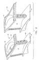
- Figure 1 is a perspective view of a turbine nozzle segment in need of repair.
- Figure 2 is a perspective view of the turbine nozzle segment of Figure 1 after the two vanes have been separated.
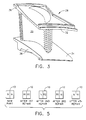
- Figure 3 is a perspective view of a new nozzle singlet used in the repair method of the present invention.
- Figure 4 is a perspective view of the turbine nozzle segment of Figure 1 after being repaired by the method of the present invention.
- Figure 5 is a diagram showing one repair schedule of the present invention.
- Figure 1 shows a turbine nozzle segment 10 having first and second nozzle vanes 12 and 14.
- the vanes 12 and 14 are disposed between an arcuate outer band 16 and an arcuate inner band 18.
- the vanes 12 and 14 define airfoils configured so as to optimally direct the combustion gases to a turbine rotor (not shown) located downstream thereof.
- the outer and inner bands 16 and 18 define the outer and inner radial boundaries, respectively, of the gas flow through the nozzle segment 10.
- the vanes 12 and 14 preferably have a plurality of conventional cooling holes 20 and trailing edge slots 22 formed therein.
- the nozzle segment 10 is preferably made of a high quality superalloy, such as a cobalt or nickel-based superalloy, and may be coated with a corrosion resistant material and/or thermal barrier coating.
- a gas turbine engine will include a plurality of such segments 10 arranged circumferentially in annular configuration. While the repair methods of the present invention are described herein with respect to a two-vane nozzle segment, it should be recognized that the present invention is equally applicable to nozzle segments having more than two vanes.
- the nozzle segment 10 can experience damage such as might result from local gas stream over-temperature or foreign objects impacting thereon. As mentioned above, a portion of the nozzle segment 10 may become damaged to the point where it cannot be repaired by known repair processes.
- the present invention is directed to a method of repairing a nozzle segment in which one of the vanes 12 and 14 is non-repairable while the other vane is repairable.
- the first vane 12 is shown in Figure 1 as having relatively minor damage and is thus a repairable vane.
- the second vane 14 is shown in Figure 1 as having extensive damage such that it is non-repairable.
- the present invention would be equally applicable to a nozzle segment in which the first vane 12 was non-repairable vane and the second vane 14 was repairable.
- the present invention includes a method of repairing the nozzle segment 10 in which the non-repairable vane 14 and some adjoining structure are replaced with a newly manufactured casting.
- the method includes the principle steps of separating the repairable vane 12 from the non-repairable vane 14 by cutting along the outer and inner bands 16 and 18.
- the segment 10 is separated into first and second sections or "singlets" 24 and 26 (see Figure 2).
- the term "singlet” refers to the assembly of a single vane disposed between a contiguous portion of the outer band 16 and a contiguous portion of the inner band 18.
- the first singlet 24 contains the repairable vane 12 and is thus salvageable
- the second singlet 26 contains the non-repairable vane 14 and is thus unsalvageable.
- the salvageable singlet 24 is subsequently joined to a newly manufactured singlet 28 that has the same configuration as the unsalvageable singlet 26 so as to result in a repaired nozzle segment.
- the new singlet 28 includes a vane 30 disposed between outer and inner band portions 32 and 34.
- the left edges (as viewed in Figure 3) of the outer and inner band portions 32 and 34 define joining surfaces 36 and 38, respectively.
- the repair method of the present invention includes an initial step of inspecting used nozzle segments to identify such segments 10 that have one vane that is repairable and another vane that is not repairable.
- a suitable segment 10 Once a suitable segment 10 has been identified, it should be stripped of any coating materials (such as corrosion or thermal resistant coatings) that may be present.
- the coating material may be stripped using any suitable technique, such as grit blasting, chemical baths, and the like, or a combination of such techniques.
- residual stresses in the segment 10 may be relieved. Without stress relief, subsequent machining and repair processes may induce deformation and resultant mismatching between the bands 16 and 18 of the salvageable singlet 24 and the corresponding outer and inner band portions 32 and 34 of the new singlet 28. Stress relief may be accomplished in any known manner such as subjecting the nozzle segment 10 to a relatively high temperature and a controlled pressure for a sufficient time.
- the next step is to separate the repairable vane 12 from the non-repairable vane 14.
- the vane separation could be done prior to stripping the coating material and relieving residual stresses. However, it is preferred that the stress relief step be carried out prior to separation. This is because relieving the stress with the segment 10 in one piece holds the bands 16 and 18 at near print dimensions without additional fixturing. Maintaining the band dimensions facilitates the subsequent joining of the new singlet 28 to the salvageable singlet 24.
- the outer and inner bands 16 and 18 Separation is accomplished by cutting the outer and inner bands 16 and 18 in two along substantially axial cuts located between the two vanes 12 and 14.
- the cutting can be performed by any conventional means such as an abrasive cutting wheel or electrical discharge machining.
- the salvageable singlet 24 retains the portions of the outer and inner bands 16 and 18 that are contiguous to the repairable vane 12.
- the cut surfaces of the outer and inner band portions 16 and 18 define joining surfaces 40 and 42, respectively, that will be joined together with corresponding joining surfaces 36 and 38 on the new singlet 28.
- the band cuts (shown in phantom lines in Figure 1) are made closer to the non-repairable vane 14 than the repairable vane 12 so as to leave excess band material on the salvageable singlet 24. This allows for machining of the band portions 16 and 18.
- the unsalvageable singlet 26, containing the non-repairable vane 14 is scrapped, and the outer and inner band portions 16 and 18 on the salvageable singlet 24 are machined so that the joining surfaces 40 and 42 will dimensionally match the joining surfaces 36 and 38 of the new singlet 28. Machining of the joining surfaces 40 and 42 also assures that the band portions 16 and 18 are properly sized so that when the salvageable singlet 24 and the new singlet 28 are joined together, the spacing between the first vane 12 and the vane 30 of the new singlet 28 meets gas flow area requirements of the nozzle segment 10.
- the next step prior to joining the two singlets 24 and 28 is to carry out an initial repair of the repairable vane 12 using known repairs such as alloy brazing, welding and the like.
- the purpose of the initial repair step is to fix relatively minor damage such as small cracks in the repairable vane 12.
- the new singlet 28 is preferably manufactured by a casting and machining process that is similar to that used for making conventional nozzle segments, except, of course, the new singlet 28 contains the single vane 30.
- the new singlet 28 Prior to being joined to the salvageable singlet 24, the new singlet 28 is preliminarily machined to remove excess stock material. Furthermore, the new singlet 28 is preliminarily machined to an in-process shape that is slightly larger than the design shape of the unsalvageable singlet 26. This in-process shape assures a smooth interface between the two singlets after joining and final machining.
- the singlets 24 and 28 are joined together, as shown in Figure 4, to restore the nozzle segment 10.
- the two singlets 24 and 28 are joined together by bonding the joining surfaces 40 and 42 of the salvageable singlet 24 to the corresponding joining surfaces 36 and 38 of the new singlet 28. Bonding may be accomplished in a conventional manner by any suitable process including brazing, welding or diffusion bonding.
- the new singlet 28 is fabricated from the same material as the salvageable singlet 24 to produce a restored nozzle segment 10 that retains its original material properties.
- the new singlet 28 is fabricated from a different material, preferably an alloy having enhanced material properties. It is often the case that during the service life of a gas turbine engine component such as a nozzle segment, improved alloys suitable for use with such components are developed. Traditionally, engine operators would have to replace existing components with new components fabricated from the improved alloy to realize the enhanced material properties. However, by fabricating the new singlet 28 from the improved alloy, the repaired nozzle segment 10 will obtain, in part, the enhanced material properties.
- the repairable vane 12 may become non-repairable.
- replacing the unsalvageable portion of the segment 10 with another new singlet fabricated from the improved alloy would result in the entire segment 10 having the enhanced material properties without the cost of purchasing an entire replacement part.
- the next step is to complete the repair of the repairable vane 12 and adjoining structure. While the initial repair step described above repaired relatively minor damage, more extensive repairable damage, such as large cracks and worn surfaces, will need to be repaired. Such additional repair may be accomplished using a standard alloy build up technique. Generally, this entails covering the nozzle segment 10 with a suitable alloy powder or paste and then heating the segment 10 to diffusion bond the added alloy thereto.
- the entire segment 10, including the newly manufactured section, is machined to its design shape.
- Performing the alloy build up process and final machining after the two singlets 24 and 28 have been joined assures that no steps or discontinuities exist at the interface of the two singlets.
- any corrosion or thermal coatings that were originally used are reapplied in a known manner.
- the repair method of the present invention relies on inspection of used nozzle segments to identify segments that have a repairable vane and a non-repairable vane. With this approach, only segments determined to have repairable and non-repairable vanes would be subject to the repair method of the present invention.
- the repair method of the present invention could be conducted on a scheduled basis. For example, Figure 5 shows one schedule for a two-vane nozzle segment in which the vanes are regularly replaced with a newly manufactured singlet using the method described above. While one possible schedule is described, it should be noted that other schedules could be utilized as well.
- the nozzle segment 10 is represented schematically at various times throughout its service life.
- the left half of the block represents one singlet and the right half of the block represents the other singlet.
- the leftmost depiction in the Figure represents the segment when it is a new part.
- each singlet is new as denoted by the N's.
- the next depiction is the segment at the time of its first repair.
- each singlet undergoes conventional repairs.
- each singlet has been repaired once, as denoted by the R1's.
- the next depiction is the segment at the time of its second repair.
- the singlet that was not replaced at the third repair is replaced with a newly manufactured singlet and the other singlet undergoes standard repair.
- one singlet is new (denoted by the N) and the other singlet has been repaired once (denoted by the RI). From here, the sequence would continue such that new replacement singlet would alternate from side to side.
Abstract
Description
- This invention relates generally to the repair of gas turbine engines and more particularly to the repair of turbine nozzle segments used in such engines.
- A gas turbine engine includes a compressor that provides pressurized air to a combustor wherein the air is mixed with fuel and ignited for generating hot combustion gases. These gases flow downstream to one or more turbines that extract energy therefrom to power the compressor and provide useful work such as powering an aircraft in flight. Aircraft engines typically include a stationary turbine nozzle disposed at the outlet of the combustor. The nozzle includes a plurality of circumferentially spaced apart vanes that channel combustion gases into a turbine rotor located downstream of the nozzle. Turbine nozzles are typically segmented around the circumference thereof with each nozzle segment having one or more nozzle vanes disposed between inner and outer bands that define the radial flowpath boundaries for the hot combustion gases flowing through the nozzle.
- Nozzle segments are exposed during operation to a high temperature, corrosive gas stream that limits the effective service life of these components. Accordingly, nozzle segments are typically fabricated from high temperature cobalt or nickel-based superalloys and are often coated with corrosion and/or heat resistant materials. Furthermore, nozzle segments are ordinarily cooled internally with cooling air extracted from the compressor to prolong service life. Even with such efforts, portions of the nozzle segments, particularly the vanes, can become cracked, corroded, and otherwise damaged such that the nozzle segments must be either repaired or replaced to maintain safe, efficient engine operation. Because nozzle segments are complex in design, are made of relatively expensive materials, and are expensive to manufacture, it is generally more desirable to repair them if possible.
- Existing repair processes include techniques such as crack repair and dimensional restoration of airfoil surfaces. However, such existing repairs are limited by local distortion and under minimum wall thicknesses, which are exceeded as a result of repeated repair and chemical stripping processes. Thus, nozzle segments may become damaged to the point where they cannot be repaired by known repair processes. In turbine nozzle segments having two or more vanes, it often occurs that one of the vanes is repairable while the other vane is non-repairable. To avoid scrapping the entire nozzle segment in such a situation, techniques for salvaging the repairable portion of the nozzle segment have been sought.
- One such technique is described in U.S. Patent No. 4,176,433 issued December 4, 1979 to Jack W. Lee, et al. This patent discloses a method of repairing nozzle segments (referred to therein as turbine vane clusters) in which the repairable vane from a damaged segment is separated from the non-repairable portion of the segment. The salvaged vane is then combined with a complementary repairable vane that has been similarly salvaged from another damaged segment. While this technique salvages repairable vanes that would otherwise be scrapped, the service life of the repaired nozzle segment is not prolonged very long because it contains used vanes that are limited in the number of future repairs that can be made. Furthermore, this technique is viable only as long as suitably complementary salvaged vanes are available to combine.
- Accordingly, there is a need for a method of repairing turbine nozzle segments in which repairable vanes are salvaged in such a manner that the service life of the nozzle segment is greatly enhanced.
- The above-mentioned need is met by the present invention which provides a method of repairing a turbine nozzle segment having at least two vanes disposed between outer and inner bands. The method includes the steps of separating the nozzle segment into a first singlet containing a repairable vane and a second singlet containing a non-repairable vane, and joining the first singlet to a newly manufactured singlet having a configuration that is similar to the second singlet.
- The invention will now be described in greater detail, by way of example, with reference to the drawings, in which:
- Figure 1 is a perspective view of a turbine nozzle segment in need of repair.
- Figure 2 is a perspective view of the turbine nozzle segment of Figure 1 after the two vanes have been separated.
- Figure 3 is a perspective view of a new nozzle singlet used in the repair method of the present invention.
- Figure 4 is a perspective view of the turbine nozzle segment of Figure 1 after being repaired by the method of the present invention.
- Figure 5 is a diagram showing one repair schedule of the present invention.
- Referring to the drawings wherein identical reference numerals denote the same elements throughout the various views, Figure 1 shows a
turbine nozzle segment 10 having first and second nozzle vanes 12 and 14. Thevanes outer band 16 and an arcuateinner band 18. Thevanes inner bands nozzle segment 10. Thevanes conventional cooling holes 20 andtrailing edge slots 22 formed therein. Thenozzle segment 10 is preferably made of a high quality superalloy, such as a cobalt or nickel-based superalloy, and may be coated with a corrosion resistant material and/or thermal barrier coating. A gas turbine engine will include a plurality ofsuch segments 10 arranged circumferentially in annular configuration. While the repair methods of the present invention are described herein with respect to a two-vane nozzle segment, it should be recognized that the present invention is equally applicable to nozzle segments having more than two vanes. - During engine operation, the
nozzle segment 10 can experience damage such as might result from local gas stream over-temperature or foreign objects impacting thereon. As mentioned above, a portion of thenozzle segment 10 may become damaged to the point where it cannot be repaired by known repair processes. The present invention is directed to a method of repairing a nozzle segment in which one of thevanes first vane 12 is shown in Figure 1 as having relatively minor damage and is thus a repairable vane. Thesecond vane 14 is shown in Figure 1 as having extensive damage such that it is non-repairable. However, it should be understood that the present invention would be equally applicable to a nozzle segment in which thefirst vane 12 was non-repairable vane and thesecond vane 14 was repairable. - The present invention includes a method of repairing the
nozzle segment 10 in which thenon-repairable vane 14 and some adjoining structure are replaced with a newly manufactured casting. The method includes the principle steps of separating therepairable vane 12 from thenon-repairable vane 14 by cutting along the outer andinner bands segment 10 is separated into first and second sections or "singlets" 24 and 26 (see Figure 2). As used herein, the term "singlet" refers to the assembly of a single vane disposed between a contiguous portion of theouter band 16 and a contiguous portion of theinner band 18. Thefirst singlet 24 contains therepairable vane 12 and is thus salvageable, and thesecond singlet 26 contains thenon-repairable vane 14 and is thus unsalvageable. Thesalvageable singlet 24 is subsequently joined to a newly manufacturedsinglet 28 that has the same configuration as theunsalvageable singlet 26 so as to result in a repaired nozzle segment. As seen in Figure 3, thenew singlet 28 includes avane 30 disposed between outer andinner band portions inner band portions surfaces - More specifically, the repair method of the present invention includes an initial step of inspecting used nozzle segments to identify
such segments 10 that have one vane that is repairable and another vane that is not repairable. Once asuitable segment 10 has been identified, it should be stripped of any coating materials (such as corrosion or thermal resistant coatings) that may be present. The coating material may be stripped using any suitable technique, such as grit blasting, chemical baths, and the like, or a combination of such techniques. In addition, residual stresses in thesegment 10 may be relieved. Without stress relief, subsequent machining and repair processes may induce deformation and resultant mismatching between thebands salvageable singlet 24 and the corresponding outer andinner band portions new singlet 28. Stress relief may be accomplished in any known manner such as subjecting thenozzle segment 10 to a relatively high temperature and a controlled pressure for a sufficient time. - The next step is to separate the
repairable vane 12 from thenon-repairable vane 14. The vane separation could be done prior to stripping the coating material and relieving residual stresses. However, it is preferred that the stress relief step be carried out prior to separation. This is because relieving the stress with thesegment 10 in one piece holds thebands new singlet 28 to thesalvageable singlet 24. - Separation is accomplished by cutting the outer and
inner bands vanes salvageable singlet 24 retains the portions of the outer andinner bands repairable vane 12. As shown in Figure 2, the cut surfaces of the outer andinner band portions surfaces surfaces new singlet 28. Preferably, the band cuts (shown in phantom lines in Figure 1) are made closer to thenon-repairable vane 14 than therepairable vane 12 so as to leave excess band material on thesalvageable singlet 24. This allows for machining of theband portions - After separation, the
unsalvageable singlet 26, containing thenon-repairable vane 14, is scrapped, and the outer andinner band portions salvageable singlet 24 are machined so that the joiningsurfaces surfaces new singlet 28. Machining of the joiningsurfaces band portions salvageable singlet 24 and thenew singlet 28 are joined together, the spacing between thefirst vane 12 and thevane 30 of thenew singlet 28 meets gas flow area requirements of thenozzle segment 10. - The next step prior to joining the two
singlets repairable vane 12 using known repairs such as alloy brazing, welding and the like. The purpose of the initial repair step is to fix relatively minor damage such as small cracks in therepairable vane 12. - The
new singlet 28 is preferably manufactured by a casting and machining process that is similar to that used for making conventional nozzle segments, except, of course, thenew singlet 28 contains thesingle vane 30. Prior to being joined to thesalvageable singlet 24, thenew singlet 28 is preliminarily machined to remove excess stock material. Furthermore, thenew singlet 28 is preliminarily machined to an in-process shape that is slightly larger than the design shape of theunsalvageable singlet 26. This in-process shape assures a smooth interface between the two singlets after joining and final machining. - Once the
singlets nozzle segment 10. The twosinglets surfaces salvageable singlet 24 to the corresponding joiningsurfaces new singlet 28. Bonding may be accomplished in a conventional manner by any suitable process including brazing, welding or diffusion bonding. - In one preferred embodiment, the
new singlet 28 is fabricated from the same material as thesalvageable singlet 24 to produce a restorednozzle segment 10 that retains its original material properties. However, in another preferred embodiment, thenew singlet 28 is fabricated from a different material, preferably an alloy having enhanced material properties. It is often the case that during the service life of a gas turbine engine component such as a nozzle segment, improved alloys suitable for use with such components are developed. Traditionally, engine operators would have to replace existing components with new components fabricated from the improved alloy to realize the enhanced material properties. However, by fabricating thenew singlet 28 from the improved alloy, the repairednozzle segment 10 will obtain, in part, the enhanced material properties. In addition, in a subsequent repair to thenozzle segment 10 using the method of the present invention, therepairable vane 12 may become non-repairable. In this case, replacing the unsalvageable portion of thesegment 10 with another new singlet fabricated from the improved alloy would result in theentire segment 10 having the enhanced material properties without the cost of purchasing an entire replacement part. - After joining the two
singlets nozzle segment 10 having a previously used section (corresponding to the salvageable singlet 24) and a newly manufactured section (corresponding to the new singlet 28) exists. The next step is to complete the repair of therepairable vane 12 and adjoining structure. While the initial repair step described above repaired relatively minor damage, more extensive repairable damage, such as large cracks and worn surfaces, will need to be repaired. Such additional repair may be accomplished using a standard alloy build up technique. Generally, this entails covering thenozzle segment 10 with a suitable alloy powder or paste and then heating thesegment 10 to diffusion bond the added alloy thereto. - Afterwards, the
entire segment 10, including the newly manufactured section, is machined to its design shape. Performing the alloy build up process and final machining after the twosinglets - As described above, the repair method of the present invention relies on inspection of used nozzle segments to identify segments that have a repairable vane and a non-repairable vane. With this approach, only segments determined to have repairable and non-repairable vanes would be subject to the repair method of the present invention. Alternatively, the repair method of the present invention could be conducted on a scheduled basis. For example, Figure 5 shows one schedule for a two-vane nozzle segment in which the vanes are regularly replaced with a newly manufactured singlet using the method described above. While one possible schedule is described, it should be noted that other schedules could be utilized as well.
- In Figure 5, the
nozzle segment 10 is represented schematically at various times throughout its service life. In each instance, the left half of the block represents one singlet and the right half of the block represents the other singlet. The leftmost depiction in the Figure represents the segment when it is a new part. Thus, each singlet is new as denoted by the N's. The next depiction is the segment at the time of its first repair. Here, assuming that neither vane has been abnormally damaged, each singlet undergoes conventional repairs. Thus, each singlet has been repaired once, as denoted by the R1's. The next depiction is the segment at the time of its second repair. This time the singlet that is in the worse shape is separated from the other singlet and replaced with a newly manufactured singlet using the steps described above, which includes standard repair to the other singlet. Thus, one singlet is new (denoted by the N), and the other singlet has been repaired twice (denoted by the R2). The next depiction is the segment at the time of its third repair. This time the singlet that was not replaced at the second repair is replaced with a newly manufactured singlet and the other singlet undergoes standard repair. Thus, one singlet is new (denoted by the N) and the other singlet has been repaired once (denoted by the R1). The last depiction is the segment at the time of its fourth repair. Here, the singlet that was not replaced at the third repair is replaced with a newly manufactured singlet and the other singlet undergoes standard repair. Thus, one singlet is new (denoted by the N) and the other singlet has been repaired once (denoted by the RI). From here, the sequence would continue such that new replacement singlet would alternate from side to side. - For the sake of good order, various aspects of the invention are set out in the following clauses:-
- 1. A method of repairing a turbine nozzle segment (10) having at least two vanes
(12, 14) disposed between outer and inner bands (16, 18), said method comprising the
steps of:
- separating said nozzle segment (10) into a first singlet (24) containing one of said vanes (12) and a second singlet (24) containing another one of said vanes (14); and
- joining said first singlet (24) to a newly manufactured singlet (28) having a configuration that is similar to said second singlet (24).
- 2. The method of clause 1 wherein said step of separating said nozzle segment (10) into first and second singlets (22, 24) comprises cutting said outer band (16) and said inner band (18) in two between said two vanes (12, 14).
- 3. The method of clause 1 further comprising the step of repairing damage in said first singlet (24).
- 4. The method of clause 3 wherein some damage in said first singlet (24) is repaired prior to joining said first singlet (24) to said newly manufactured singlet (28) and some damage in said first singlet (24) is repaired subsequently to joining said first singlet (24) to said newly manufactured singlet (28).
- 5. The method of clause 1 wherein said newly manufactured singlet (28) has an in-process shape that is larger than said second singlet (24).
- 6. The method of clause 1 further comprising the step of applying an alloy build up to said nozzle segment (10), subsequently to joining said first singlet (24) to said newly manufactured singlet (28).
- 7. The method of clause 6 further comprising the step of machining said nozzle segment (10) to its design shape subsequently to applying said alloy build up.
- 8. The method of clause 1 wherein said newly manufactured singlet (28) is fabricated-from the same material as said first ringlet (24).
- 9. The method of clause 1 wherein said newly manufactured ringlet (28) is fabricated from a material that has enhanced material properties with respect to the material that said first ringlet (24) is fabricated from.
- 10. The method of clause 1 further comprising the steps of separating said first
ringlet (24) from said newly manufactured singlet (28); and
joining said newly manufactured ringlet (28) to another newly manufactured singlet (28) having a configuration that is similar to said first singlet 10 (24). - 11. A method of repairing a turbine nozzle segment (10) having a repairable vane
(12) and a non-repairable vane (14) disposed between a first outer band (16) and a
first inner band (18), said method comprising the steps of providing a newly
manufactured ringlet (28) including a vane (30) disposed between a second outer band
(32) having a first joining surface (36) and a second inner band (34) having a second
joining surface (38);
- cutting said first outer band (16) and said first inner band (18) of said nozzle segment (10) in two between said two vanes (12, 14) so as to separate said nozzle segment (10) into a first singlet (24) containing said repairable vane (12) and a second singlet (24) containing said non-repairable vane (14), wherein said first ringlet (24) includes a third joining surface (40) on said first outer band (16) and a fourth joining surface (42) on said first inner band (18);
- repairing damage in said first singlet (24); and
- joining said first singlet (24) to said newly manufactured singlet (28) by bonding said first and third joining surfaces (36, 40) together and said second and fourth joining surfaces (38, 42) together.
- 12. The method of clause 11 wherein said newly manufactured singlet (28) has are in-process shape that is larger than said second singlet (24).
- 13. The method of clause 11 further comprising the step of applying an alloy build up to said nozzle segment (10), subsequently to joining said first singlet (24) to said newly manufactured singlet (28).
- 14. The method of clause 13 further comprising the step of machining said nozzle segment (10) to its design shape subsequently to applying said alloy build up.
- 15. The method of clause 11 wherein said newly manufactured singlet (28) is fabricated from the same material as said first singlet (24)
- 16. The method of clause 11 wherein said newly manufactured singlet (28) is fabricated from a material that has enhanced material properties with respect to the material that said first singlet (24) is fabricated from.
- 17. The method of clause 11 further comprising the step of machining said third and fourth joining surfaces (40, 42) prior to joining said first singlet (24) to said newly manufactured singlet (28).
- 18. The method of clause 11 further comprising the steps of separating said first
singlet (24) from said newly manufactured singlet (28); and
joining said newly manufactured singlet (28) to another newly manufactured singlet having a configuration that is similar to said first singlet (24). - 19. A turbine nozzle segment (10) comprising:
- an outer band (16);
- an inner band (18); and
- first and second vanes (12, 14) disposed between said outer and inner bands (16, 18), wherein said first vane (12) and contiguous portions of said outer and inner bands (16, 18) define a first section of said nozzle segment (10) and said second vane (14) and respectively contiguous portions of said outer and inner bands (16, 18) define a second section of said nozzle segment (10), said first section being previously used and said second section being newly manufactured.
- 20. The nozzle segment (10) of clause 19 wherein said first and second sections are fabricated from the same material.
- 21. The nozzle segment (10) of clause 19 wherein said second section is fabricated from a material that has enhanced material properties with respect to the material that said first section is fabricated from.
-
Claims (10)
- A method of repairing a turbine nozzle segment (10) having at least two vanes (12, 14) disposed between outer and inner bands (16, 18), said method comprising the steps of:separating said nozzle segment (10) into a first singlet (24) containing one of said vanes (12) and a second singlet (24) containing another one of said vanes (14); andjoining said first singlet (24) to a newly manufactured singlet (28) having a configuration that is similar to said second singlet (24).
- The method of claim 1 wherein said step of separating said nozzle segment (10) into first and second singlets (22, 24) comprises cutting said outer band (16) and said inner band (18) in two between said two vanes (12, 14).
- The method of claim 1 or 2 further comprising the step of repairing damage in said first singlet (24).
- The method of claim 3 wherein some damage in said first singlet (24) is repaired prior to joining said first singlet (24) to said newly manufactured singlet (28) and some damage in said first singlet (24) is repaired subsequently to joining said first singlet (24) to said newly manufactured singlet (28).
- A method of repairing a turbine nozzle segment (10) having a repairable vane (12) and a non-repairable vane (14) disposed between a first outer band (16) and a first inner band (18), said method comprising the steps of:providing a newly manufactured ringlet (28) including a vane (30) disposed between a second outer band (32) having a first joining surface (36) and a second inner band (34) having a second joining surface (38);cutting said first outer band (16) and said first inner band (18) of said nozzle segment (10) in two between said two vanes (12, 14) so as to separate said nozzle segment (10) into a first singlet (24) containing said repairable vane (12) and a second singlet (24) containing said non-repairable vane (14), wherein said first ringlet (24) includes a third joining surface (40) on said first outer band (16) and a fourth joining surface (42) on said first inner band (18);repairing damage in said first singlet (24); andjoining said first singlet (24) to said newly manufactured singlet (28) by bonding said first and third joining surfaces (36, 40) together and said second and fourth joining surfaces (38, 42) together.
- The method of claim 5 wherein said newly manufactured singlet (28) has are in-process shape that is larger than said second singlet (24).
- The method of claim 5 or 6 further comprising the step of applying an alloy build up to said nozzle segment (10), subsequently to joining said first singlet (24) to said newly manufactured singlet (28).
- A turbine nozzle segment (10) comprising:an outer band (16);an inner band (18); andfirst and second vanes (12, 14) disposed between said outer and inner bands (16, 18), wherein said first vane (12) and contiguous portions of said outer and inner bands (16, 18) define a first section of said nozzle segment (10) and said second vane (14) and respectively contiguous portions of said outer and inner bands (16, 18) define a second section of said nozzle segment (10), said first section being previously used and said second section being newly manufactured.
- The nozzle segment (10) of claim 8 wherein said first and second sections are fabricated from the same material.
- The nozzle segment (10) of claim 8 or 9 wherein said second section is fabricated from a material that has enhanced material properties with respect to the material that said first section is fabricated from.
Applications Claiming Priority (2)
| Application Number | Priority Date | Filing Date | Title |
|---|---|---|---|
| US09/438,969 US6785961B1 (en) | 1999-11-12 | 1999-11-12 | Turbine nozzle segment and method of repairing same |
| US438969 | 1999-11-12 |
Publications (3)
| Publication Number | Publication Date |
|---|---|
| EP1099508A2 true EP1099508A2 (en) | 2001-05-16 |
| EP1099508A3 EP1099508A3 (en) | 2002-11-27 |
| EP1099508B1 EP1099508B1 (en) | 2007-09-12 |
Family
ID=23742766
Family Applications (1)
| Application Number | Title | Priority Date | Filing Date |
|---|---|---|---|
| EP00309903A Expired - Lifetime EP1099508B1 (en) | 1999-11-12 | 2000-11-08 | Turbine nozzle segment and method of repairing same |
Country Status (11)
| Country | Link |
|---|---|
| US (2) | US6785961B1 (en) |
| EP (1) | EP1099508B1 (en) |
| JP (1) | JP4659968B2 (en) |
| KR (1) | KR100495573B1 (en) |
| CN (1) | CN100371126C (en) |
| BR (1) | BR0005334B1 (en) |
| DE (1) | DE60036351T2 (en) |
| MX (1) | MXPA00011074A (en) |
| PL (1) | PL194259B1 (en) |
| SG (1) | SG90191A1 (en) |
| TR (1) | TR200003284A2 (en) |
Cited By (3)
| Publication number | Priority date | Publication date | Assignee | Title |
|---|---|---|---|---|
| KR100495573B1 (en) * | 1999-11-12 | 2005-06-16 | 제너럴 일렉트릭 캄파니 | Turbine nozzle segment and method of repairing same |
| WO2008009270A2 (en) * | 2006-07-20 | 2008-01-24 | Mtu Aero Engines Gmbh | Method for repairing a guide blade segment for a jet engine |
| EP1995409A3 (en) * | 2007-05-22 | 2010-12-01 | United Technologies Corporation | Repair method for turbine vanes |
Families Citing this family (19)
| Publication number | Priority date | Publication date | Assignee | Title |
|---|---|---|---|---|
| US6994520B2 (en) | 2004-05-26 | 2006-02-07 | General Electric Company | Internal core profile for a turbine nozzle airfoil |
| US7220100B2 (en) * | 2005-04-14 | 2007-05-22 | General Electric Company | Crescentic ramp turbine stage |
| US20080038106A1 (en) * | 2005-10-05 | 2008-02-14 | Oshkosh Truck Corporation | Mobile lift device |
| DE102006016703A1 (en) * | 2006-04-08 | 2007-10-11 | Mtu Aero Engines Gmbh | Method of repairing a vane segment |
| US20070274854A1 (en) * | 2006-05-23 | 2007-11-29 | General Electric Company | Method of making metallic composite foam components |
| US20070295785A1 (en) * | 2006-05-31 | 2007-12-27 | General Electric Company | Microwave brazing using mim preforms |
| US7845549B2 (en) * | 2006-05-31 | 2010-12-07 | General Electric Company | MIM braze preforms |
| US7837437B2 (en) * | 2007-03-07 | 2010-11-23 | General Electric Company | Turbine nozzle segment and repair method |
| US7798773B2 (en) * | 2007-08-06 | 2010-09-21 | United Technologies Corporation | Airfoil replacement repair |
| US20090113706A1 (en) * | 2007-11-06 | 2009-05-07 | General Electric Company | Craze crack repair of combustor liners |
| US20090274562A1 (en) * | 2008-05-02 | 2009-11-05 | United Technologies Corporation | Coated turbine-stage nozzle segments |
| US20100122973A1 (en) * | 2008-11-20 | 2010-05-20 | General Electric Company | Welding process |
| US8245399B2 (en) * | 2009-01-20 | 2012-08-21 | United Technologies Corporation | Replacement of part of engine case with dissimilar material |
| US8763403B2 (en) | 2010-11-19 | 2014-07-01 | United Technologies Corporation | Method for use with annular gas turbine engine component |
| PL220908B1 (en) | 2012-08-09 | 2016-01-29 | Gen Electric | Regeneration of the steam turbine blading carrier using a bonding method in the solid state |
| US10260349B2 (en) * | 2016-10-12 | 2019-04-16 | General Electric Company | Tubine blade and related method of forming |
| CN106514149B (en) * | 2016-11-29 | 2018-08-10 | 沈阳黎明航空发动机(集团)有限责任公司 | A kind of processing method of monoblock type guider |
| US11043146B2 (en) * | 2018-08-20 | 2021-06-22 | Raytheon Technologies Corporation | Fan blade refurbishment training device |
| CN113513369B (en) * | 2021-07-26 | 2023-01-24 | 中国船舶重工集团公司第七0三研究所 | Method for adjusting throat area of turbine blade of marine gas turbine |
Citations (4)
| Publication number | Priority date | Publication date | Assignee | Title |
|---|---|---|---|---|
| US4176433A (en) * | 1978-06-29 | 1979-12-04 | United Technologies Corporation | Method of remanufacturing turbine vane clusters for gas turbine engines |
| US5269057A (en) * | 1991-12-24 | 1993-12-14 | Freedom Forge Corporation | Method of making replacement airfoil components |
| US5758416A (en) * | 1996-12-05 | 1998-06-02 | General Electric Company | Method for repairing a turbine engine vane segment |
| US5813832A (en) * | 1996-12-05 | 1998-09-29 | General Electric Company | Turbine engine vane segment |
Family Cites Families (18)
| Publication number | Priority date | Publication date | Assignee | Title |
|---|---|---|---|---|
| US4096614A (en) * | 1975-09-02 | 1978-06-27 | General Electric Company | Method and apparatus for removing stator vanes |
| US4141124A (en) * | 1977-08-29 | 1979-02-27 | United Technologies Corporation | Method and apparatus for removing one or more vanes from a gas turbine compressor stator |
| US4194869A (en) | 1978-06-29 | 1980-03-25 | United Technologies Corporation | Stator vane cluster |
| US4326833A (en) * | 1980-03-19 | 1982-04-27 | General Electric Company | Method and replacement member for repairing a gas turbine engine blade member |
| US4305697A (en) * | 1980-03-19 | 1981-12-15 | General Electric Company | Method and replacement member for repairing a gas turbine engine vane assembly |
| US4400915A (en) * | 1980-06-02 | 1983-08-30 | United Technologies Corporation | Fixture for restoring a face on the shroud of a rotor blade |
| US4741128A (en) * | 1986-08-14 | 1988-05-03 | Amoco Corporation | Cutter assembly |
| US5060842A (en) | 1990-04-09 | 1991-10-29 | Westinghouse Electric Corp. | Method for refurbishing nozzle block vanes of a steam turbine |
| US5272809A (en) * | 1990-09-04 | 1993-12-28 | United Technologies Corporation | Technique for direct bonding cast and wrought materials |
| US5197190A (en) * | 1991-03-04 | 1993-03-30 | United Technologies Corporation | Fabrication of repair method for an integrally bladed rotor |
| US5248240A (en) * | 1993-02-08 | 1993-09-28 | General Electric Company | Turbine stator vane assembly |
| US5560841A (en) | 1994-10-11 | 1996-10-01 | United Technologies Corporation | Stator vane extraction |
| US5697151A (en) * | 1995-08-07 | 1997-12-16 | General Electric Company | Method for repairing partitions of a turbine diaphragm |
| US5765993A (en) * | 1996-09-27 | 1998-06-16 | Chromalloy Gas Turbine Corporation | Replacement vane assembly for fan exit guide |
| EP0882545A3 (en) * | 1997-06-05 | 1999-03-10 | Mtu Motoren- Und Turbinen-Union MàNchen Gmbh | Repairing method for integrally cast stator rings of a turbine |
| US6173491B1 (en) | 1999-08-12 | 2001-01-16 | Chromalloy Gas Turbine Corporation | Method for replacing a turbine vane airfoil |
| US6154959A (en) * | 1999-08-16 | 2000-12-05 | Chromalloy Gas Turbine Corporation | Laser cladding a turbine engine vane platform |
| US6785961B1 (en) * | 1999-11-12 | 2004-09-07 | General Electric Corporation | Turbine nozzle segment and method of repairing same |
-
1999
- 1999-11-12 US US09/438,969 patent/US6785961B1/en not_active Expired - Fee Related
-
2000
- 2000-11-02 SG SG200006320A patent/SG90191A1/en unknown
- 2000-11-08 EP EP00309903A patent/EP1099508B1/en not_active Expired - Lifetime
- 2000-11-08 DE DE60036351T patent/DE60036351T2/en not_active Expired - Lifetime
- 2000-11-08 PL PL343748A patent/PL194259B1/en unknown
- 2000-11-08 TR TR2000/03284A patent/TR200003284A2/en unknown
- 2000-11-09 KR KR10-2000-0066418A patent/KR100495573B1/en not_active IP Right Cessation
- 2000-11-10 JP JP2000342874A patent/JP4659968B2/en not_active Expired - Fee Related
- 2000-11-10 BR BRPI0005334-1A patent/BR0005334B1/en not_active IP Right Cessation
- 2000-11-10 MX MXPA00011074A patent/MXPA00011074A/en active IP Right Grant
- 2000-11-11 CN CNB001355244A patent/CN100371126C/en not_active Expired - Fee Related
-
2001
- 2001-04-06 US US09/828,019 patent/US20030215329A1/en not_active Abandoned
Patent Citations (4)
| Publication number | Priority date | Publication date | Assignee | Title |
|---|---|---|---|---|
| US4176433A (en) * | 1978-06-29 | 1979-12-04 | United Technologies Corporation | Method of remanufacturing turbine vane clusters for gas turbine engines |
| US5269057A (en) * | 1991-12-24 | 1993-12-14 | Freedom Forge Corporation | Method of making replacement airfoil components |
| US5758416A (en) * | 1996-12-05 | 1998-06-02 | General Electric Company | Method for repairing a turbine engine vane segment |
| US5813832A (en) * | 1996-12-05 | 1998-09-29 | General Electric Company | Turbine engine vane segment |
Cited By (6)
| Publication number | Priority date | Publication date | Assignee | Title |
|---|---|---|---|---|
| KR100495573B1 (en) * | 1999-11-12 | 2005-06-16 | 제너럴 일렉트릭 캄파니 | Turbine nozzle segment and method of repairing same |
| WO2008009270A2 (en) * | 2006-07-20 | 2008-01-24 | Mtu Aero Engines Gmbh | Method for repairing a guide blade segment for a jet engine |
| WO2008009270A3 (en) * | 2006-07-20 | 2008-03-06 | Mtu Aero Engines Gmbh | Method for repairing a guide blade segment for a jet engine |
| US8914975B2 (en) | 2006-07-20 | 2014-12-23 | Mtu Aero Engines Gmbh | Method for repairing a guide blade segment for a jet engine |
| EP1995409A3 (en) * | 2007-05-22 | 2010-12-01 | United Technologies Corporation | Repair method for turbine vanes |
| US8220150B2 (en) | 2007-05-22 | 2012-07-17 | United Technologies Corporation | Split vane cluster repair method |
Also Published As
| Publication number | Publication date |
|---|---|
| PL194259B1 (en) | 2007-05-31 |
| JP2001152873A (en) | 2001-06-05 |
| DE60036351T2 (en) | 2008-05-08 |
| US20030215329A1 (en) | 2003-11-20 |
| TR200003284A2 (en) | 2001-09-21 |
| KR20010060282A (en) | 2001-07-06 |
| JP4659968B2 (en) | 2011-03-30 |
| CN100371126C (en) | 2008-02-27 |
| MXPA00011074A (en) | 2003-04-25 |
| BR0005334B1 (en) | 2008-11-18 |
| EP1099508A3 (en) | 2002-11-27 |
| KR100495573B1 (en) | 2005-06-16 |
| BR0005334A (en) | 2001-07-03 |
| US6785961B1 (en) | 2004-09-07 |
| EP1099508B1 (en) | 2007-09-12 |
| SG90191A1 (en) | 2002-07-23 |
| PL343748A1 (en) | 2001-05-21 |
| DE60036351D1 (en) | 2007-10-25 |
| CN1295900A (en) | 2001-05-23 |
Similar Documents
| Publication | Publication Date | Title |
|---|---|---|
| EP1099508B1 (en) | Turbine nozzle segment and method of repairing same | |
| US6494677B1 (en) | Turbine nozzle segment and method of repairing same | |
| US6905308B2 (en) | Turbine nozzle segment and method of repairing same | |
| US6416278B1 (en) | Turbine nozzle segment and method of repairing same | |
| CA2529337C (en) | Turbine nozzle segment and method of repairing same | |
| CA2448465C (en) | Fabricated repair of cast nozzle | |
| EP1319802A2 (en) | Turbine nozzle segment and method of repairing same | |
| CA2623675C (en) | Turbine nozzle segment and repair method |
Legal Events
| Date | Code | Title | Description |
|---|---|---|---|
| PUAI | Public reference made under article 153(3) epc to a published international application that has entered the european phase |
Free format text: ORIGINAL CODE: 0009012 |
|
| AK | Designated contracting states |
Kind code of ref document: A2 Designated state(s): AT BE CH CY DE DK ES FI FR GB GR IE IT LI LU MC NL PT SE TR |
|
| AX | Request for extension of the european patent |
Free format text: AL;LT;LV;MK;RO;SI |
|
| PUAL | Search report despatched |
Free format text: ORIGINAL CODE: 0009013 |
|
| AK | Designated contracting states |
Kind code of ref document: A3 Designated state(s): AT BE CH CY DE DK ES FI FR GB GR IE IT LI LU MC NL PT SE TR |
|
| AX | Request for extension of the european patent |
Free format text: AL;LT;LV;MK;RO;SI |
|
| 17P | Request for examination filed |
Effective date: 20030527 |
|
| AKX | Designation fees paid |
Designated state(s): DE FR GB |
|
| 17Q | First examination report despatched |
Effective date: 20031028 |
|
| 17Q | First examination report despatched |
Effective date: 20031028 |
|
| GRAP | Despatch of communication of intention to grant a patent |
Free format text: ORIGINAL CODE: EPIDOSNIGR1 |
|
| GRAS | Grant fee paid |
Free format text: ORIGINAL CODE: EPIDOSNIGR3 |
|
| GRAA | (expected) grant |
Free format text: ORIGINAL CODE: 0009210 |
|
| AK | Designated contracting states |
Kind code of ref document: B1 Designated state(s): DE FR GB |
|
| REG | Reference to a national code |
Ref country code: GB Ref legal event code: FG4D |
|
| REF | Corresponds to: |
Ref document number: 60036351 Country of ref document: DE Date of ref document: 20071025 Kind code of ref document: P |
|
| ET | Fr: translation filed | ||
| PLBE | No opposition filed within time limit |
Free format text: ORIGINAL CODE: 0009261 |
|
| STAA | Information on the status of an ep patent application or granted ep patent |
Free format text: STATUS: NO OPPOSITION FILED WITHIN TIME LIMIT |
|
| 26N | No opposition filed |
Effective date: 20080613 |
|
| REG | Reference to a national code |
Ref country code: FR Ref legal event code: PLFP Year of fee payment: 16 |
|
| PGFP | Annual fee paid to national office [announced via postgrant information from national office to epo] |
Ref country code: GB Payment date: 20151127 Year of fee payment: 16 Ref country code: DE Payment date: 20151127 Year of fee payment: 16 |
|
| PGFP | Annual fee paid to national office [announced via postgrant information from national office to epo] |
Ref country code: FR Payment date: 20151117 Year of fee payment: 16 |
|
| REG | Reference to a national code |
Ref country code: DE Ref legal event code: R119 Ref document number: 60036351 Country of ref document: DE |
|
| GBPC | Gb: european patent ceased through non-payment of renewal fee |
Effective date: 20161108 |
|
| REG | Reference to a national code |
Ref country code: FR Ref legal event code: ST Effective date: 20170731 |
|
| PG25 | Lapsed in a contracting state [announced via postgrant information from national office to epo] |
Ref country code: FR Free format text: LAPSE BECAUSE OF NON-PAYMENT OF DUE FEES Effective date: 20161130 |
|
| PG25 | Lapsed in a contracting state [announced via postgrant information from national office to epo] |
Ref country code: GB Free format text: LAPSE BECAUSE OF NON-PAYMENT OF DUE FEES Effective date: 20161108 Ref country code: DE Free format text: LAPSE BECAUSE OF NON-PAYMENT OF DUE FEES Effective date: 20170601 |