EP1099409A2 - Combined biplane angiography and CT apparatus - Google Patents
Combined biplane angiography and CT apparatus Download PDFInfo
- Publication number
- EP1099409A2 EP1099409A2 EP00309924A EP00309924A EP1099409A2 EP 1099409 A2 EP1099409 A2 EP 1099409A2 EP 00309924 A EP00309924 A EP 00309924A EP 00309924 A EP00309924 A EP 00309924A EP 1099409 A2 EP1099409 A2 EP 1099409A2
- Authority
- EP
- European Patent Office
- Prior art keywords
- gantry
- top plate
- imaging
- frontal
- lateral
- Prior art date
- Legal status (The legal status is an assumption and is not a legal conclusion. Google has not performed a legal analysis and makes no representation as to the accuracy of the status listed.)
- Withdrawn
Links
Images


Classifications
-
- A—HUMAN NECESSITIES
- A61—MEDICAL OR VETERINARY SCIENCE; HYGIENE
- A61B—DIAGNOSIS; SURGERY; IDENTIFICATION
- A61B6/00—Apparatus or devices for radiation diagnosis; Apparatus or devices for radiation diagnosis combined with radiation therapy equipment
- A61B6/04—Positioning of patients; Tiltable beds or the like
-
- A—HUMAN NECESSITIES
- A61—MEDICAL OR VETERINARY SCIENCE; HYGIENE
- A61B—DIAGNOSIS; SURGERY; IDENTIFICATION
- A61B6/00—Apparatus or devices for radiation diagnosis; Apparatus or devices for radiation diagnosis combined with radiation therapy equipment
- A61B6/44—Constructional features of apparatus for radiation diagnosis
- A61B6/4429—Constructional features of apparatus for radiation diagnosis related to the mounting of source units and detector units
- A61B6/4435—Constructional features of apparatus for radiation diagnosis related to the mounting of source units and detector units the source unit and the detector unit being coupled by a rigid structure
- A61B6/4441—Constructional features of apparatus for radiation diagnosis related to the mounting of source units and detector units the source unit and the detector unit being coupled by a rigid structure the rigid structure being a C-arm or U-arm
-
- A—HUMAN NECESSITIES
- A61—MEDICAL OR VETERINARY SCIENCE; HYGIENE
- A61B—DIAGNOSIS; SURGERY; IDENTIFICATION
- A61B6/00—Apparatus or devices for radiation diagnosis; Apparatus or devices for radiation diagnosis combined with radiation therapy equipment
- A61B6/02—Arrangements for diagnosis sequentially in different planes; Stereoscopic radiation diagnosis
- A61B6/03—Computed tomography [CT]
- A61B6/032—Transmission computed tomography [CT]
-
- A—HUMAN NECESSITIES
- A61—MEDICAL OR VETERINARY SCIENCE; HYGIENE
- A61B—DIAGNOSIS; SURGERY; IDENTIFICATION
- A61B6/00—Apparatus or devices for radiation diagnosis; Apparatus or devices for radiation diagnosis combined with radiation therapy equipment
- A61B6/44—Constructional features of apparatus for radiation diagnosis
- A61B6/4429—Constructional features of apparatus for radiation diagnosis related to the mounting of source units and detector units
- A61B6/4464—Constructional features of apparatus for radiation diagnosis related to the mounting of source units and detector units the source unit or the detector unit being mounted to ceiling
-
- A—HUMAN NECESSITIES
- A61—MEDICAL OR VETERINARY SCIENCE; HYGIENE
- A61B—DIAGNOSIS; SURGERY; IDENTIFICATION
- A61B6/00—Apparatus or devices for radiation diagnosis; Apparatus or devices for radiation diagnosis combined with radiation therapy equipment
- A61B6/50—Apparatus or devices for radiation diagnosis; Apparatus or devices for radiation diagnosis combined with radiation therapy equipment specially adapted for specific body parts; specially adapted for specific clinical applications
- A61B6/504—Apparatus or devices for radiation diagnosis; Apparatus or devices for radiation diagnosis combined with radiation therapy equipment specially adapted for specific body parts; specially adapted for specific clinical applications for diagnosis of blood vessels, e.g. by angiography
Definitions
- the present invention relates to a biplane vascular imaging (angiography)/CT apparatus, and more particularly to a biplane angiography/CT apparatus which can alternately perform CT imaging and simultaneous angiographic imaging in two planes in the anterior-posterior direction, i.e., the frontal direction and in the left-right direction, i.e., the lateral direction, of a subject, and which does not make the subject feel discomfort and has improved safety.
- EP 919185A1 discloses an angiography/CT apparatus comprising a top plate for laying a subject, a frontal arm comprising an X-ray tube and an X-ray image receiving device for performing angiographic imaging vertically across the subject laid on the top plate, a CT gantry comprising an X-ray tube and an X-ray detector for performing CT imaging on the subject laid on the top plate, and top plate moving means which allows the top plate to horizontally move.
- the angiographic imaging is achieved in a frontal plane by moving the top plate to the position of the frontal arm using the top plate moving means for moving the top plate in its longitudinal direction.
- the CT imaging is achieved by moving the top plate to the position of the CT gantry using the top plate moving means. Therefore, the angiographic imaging in the frontal plane and the CT imaging can be alternately performed in a cycle of, for example, five minutes, by alternately moving the top plate between the two positions.
- Angiographic imaging may be performed not only in the frontal plane but also in a lateral plane horizontally across the subject.
- an apparatus which can alternately perform CT imaging and simultaneous angiographic imaging in two planes, i.e., the frontal and lateral planes.
- bi-directional angiographic imaging involves a frontal arm and a lateral arm extending in two directions. If the CT imaging apparatus and these biplane apparatuses are simply arranged in the longitudinal direction of the top plate, the overhead traveling lateral arm interferes with the CT gantry.
- the CT imaging apparatus is therefore placed at a position opposite to the biplane apparatuses across a patient table (i.e., at 180°) or placed at 90°, and the top plate is rotated and moved in its longitudinal direction between the apparatuses to accommodate all these apparatuses.
- the present invention provides a biplane angiography/CT apparatus which alternately performs CT imaging and simultaneous angiographic imaging by arms extending in two directions, i.e., a frontal arm and a lateral arm, and which does not make a subject feel discomfort and has improved safety.
- a biplane angiography/CT apparatus comprising: a top plate for laying a subject; a frontal arm comprising an X-ray tube and an X-ray image receiving device for performing angiographic imaging vertically across the subject laid on the top plate; a lateral arm comprising an X-ray tube and an X-ray image receiving device for performing angiographic imaging horizontally across the subject laid on the top plate; a CT gantry comprising an X-ray tube and an X-ray detector for performing CT imaging on the subject laid on the top plate; and control means for retracting the CT gantry to a position not hindering the angiographic imaging and moving the frontal and lateral arms to an angiographic imaging position based on a command by an operator, and for retracting the frontal and lateral arms to positions not hindering the CT imaging and moving the CT gantry to a CT imaging position based on a command by the operator.
- the biplane angiography/CT apparatus of the first aspect is provided with a lateral arm for performing angiographic imaging in a lateral plane, in addition to a frontal arm and a CT gantry.
- a lateral arm for performing angiographic imaging in a lateral plane, in addition to a frontal arm and a CT gantry.
- This allows simultaneous angiographic imaging in two planes, i.e., the frontal and lateral planes.
- the CT gantry is retracted to a position not hindering the angiographic imaging and the frontal and lateral arms are moved to an angiographic imaging position
- CT imaging is to be performed
- the frontal and lateral arms are retracted to positions not hindering the CT imaging and the CT gantry is moved to a CT imaging position.
- a biplane angiography/CT apparatus comprising: a top plate for laying a subject; a frontal arm comprising an X-ray tube and an X-ray image receiving device for performing angiographic imaging vertically across the subject laid on the top plate; a lateral arm comprising an X-ray tube and an X-ray image receiving device for performing angiographic imaging horizontally across the subject laid on the top plate; a CT gantry comprising an X-ray tube and an X-ray detector for performing CT imaging on the subject laid on the top plate; top plate moving means for allowing the top plate to horizontally move in its longitudinal direction; frontal arm swiveling means for allowing the frontal arm to swivel around a certain axis; lateral arm moving means for allowing the lateral arm to move in a certain direction; and CT gantry moving means for allowing the CT gantry to move in a certain direction.
- the biplane angiography/CT apparatus of the second aspect is provided with a lateral arm for performing angiographic imaging in a lateral plane, in addition to a frontal arm and a CT gantry.
- a lateral arm for performing angiographic imaging in a lateral plane, in addition to a frontal arm and a CT gantry.
- This allows simultaneous angiographic imaging in two planes, i.e., frontal and lateral planes.
- the above configuration especially reduces interference of the CT gantry with the frontal and lateral arms.
- the CT gantry is retracted to a position not hindering the angiographic imaging and the lateral arms can be moved to an angiographic imaging position, and the frontal and lateral arms are retracted to positions not hindering the CT imaging and the CT gantry can be moved to a CT imaging position.
- the frontal and lateral arms with the CT gantry can be prevented. The subject is thus protected from discomfort due to the movement of the top plate
- a switch be provided on the control means for the operator to input the command to retract the CT gantry to the position not hindering the angiographic imaging.
- a switch be provided on the control means for the operator to input the command to move the frontal and lateral arms to the angiographic imaging position.
- a switch be provided on the control means for the operator to input the command to retract the CT gantry to the position not hindering the angiographic imaging and to move the frontal and lateral arms to the angiographic imaging position.
- a switch be provided on the control means for the operator to input the command to retract the frontal and lateral arms to the positions not hindering the CT imaging.
- a switch be provided on the control means for the operator to input the command to move the CT gantry to the CT imaging position.
- a switch be provided on the control means for the operator to input the command to retract the frontal and lateral arms to the positions not hindering the CT imaging and to move the CT gantry to the CT imaging position.
- the lateral arm moving means may be configured to horizontally move the lateral arm in the longitudinal direction of the top plate
- the CT gantry moving means may be configured to horizontally move the CT gantry in the transverse direction of the top plate.
- the lateral arm moving means may be configured to horizontally move the lateral arm in the transverse direction of the top plate
- the CT gantry moving means may be configured to horizontally move the CT gantry in the longitudinal direction of the top plate.
- the lateral arm moving means may be configured to rotate the lateral arm around the longitudinal direction of the top plate.
- the CT gantry moving means may be configured to horizontally turn the CT gantry.
- the lateral arm moving means may be configured to horizontally turn the lateral arm.
- the top plate is preferably configured to be vertically movable so the subject can easily climb on and off the top plate.
- the top plate is preferably configured to be horizontally rotatable so the subject can easily climb on and off the top plate.
- the lateral arm may be configured to be swung up to the ceiling to prevent interference with the CT gantry.
- a lateral arm for performing angiographic imaging in a lateral plane is provided in addition to a frontal arm and CT gantry, simultaneous angiographic imaging in two planes, frontal and lateral, is possible.
- the CT gantry is retracted to a position not hindering the angiographic imaging and the frontal and lateral arms are moved to an angiographic imaging position, and when CT imaging is to be performed, the frontal and lateral arms are retracted to positions not hindering the CT imaging and the CT gantry is moved to a CT imaging position.
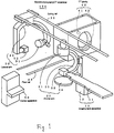
- Figure 1 is a perspective view of a biplane angiography/CT apparatus 100 in accordance with a first embodiment of the present invention.
- the biplane angiography/CT apparatus 100 comprises: an imaging table apparatus 10 comprising a top plate 11 for laying a subject and a top plate driving apparatus 12 which allows the top plate 11 to horizontally move in its longitudinal direction and to vertically move; a frontal arm 20 comprising an X-ray tube 22 and an X-ray image receiving device 21 for performing angiographic imaging vertically across the subject laid on the top plate 11; a lateral arm 30 comprising an X-ray tube 32 and an X-ray image receiving device 31 for performing angiographic imaging horizontally across the subject laid on the top plate 11; a CT gantry 40 comprising an X-ray tube 41 and an X-ray detector 42 for performing CT imaging on the subject laid on the top plate 11; and control apparatus 50 for retracting the CT gantry 40 to a position not hindering angiographic imaging and moving the frontal and lateral arms 20 and 30 to an angiographic imaging position based on a command by an operator, as shown in Figure 2, and for retracting the frontal and
- the X-ray tube 22 and X-ray image receiving device 21 of the frontal arm 20 are attached respectively to the ends of a frontal C arm 23.
- the frontal C arm 23 is supported on a horizontal swivel base 24 placed on the floor.
- the frontal C arm 23 is rotatable along its arc.
- the X-ray tube 32 and X-ray image receiving device 31 of the lateral arm 30 are attached respectively to the ends of a lateral C arm 33.
- the lateral C arm 33 is supported by a ceiling rail 35 suspended from the ceiling, and is horizontally movable along the ceiling rail 35.
- the ceiling rail 35 extends in the longitudinal direction of the top plate 11. That is, the lateral C arm 33 is horizontally movable in the longitudinal direction of the top plate 11.
- the lateral C arm 33 is rotatable along its arc.
- the CT gantry 40 is supported on a floor rail 45 disposed on the floor, and is horizontally movable along the floor rail 45.
- the floor rail 45 is extended in the transverse direction of the top plate 11. That is, the CT gantry 40 is horizontally movable in the transverse direction of the top plate 11.
- the present embodiment is configured so that the lateral arm 30 is horizontally moved in the longitudinal direction of the top plate 11 and the CT gantry 40 is horizontally moved in the transverse direction of the top plate 11.
- the control apparatus 50 has a monitor function of constantly monitoring the position, angle and height of the top plate 11, the position and angle of the frontal arm 20, the position and angle of the lateral arm 30, and the position and tilt angle of the CT gantry 40.
- the control apparatus 50 interlock-controls the present apparatus and the subject to maintain safety, and produces alarms and operation guidance as necessary.
- Figure 4 is a flow chart of a biplane angiography moving process executed by the control apparatus 50.
- Step B1 the operator depresses a CT gantry parking switch provided on the control apparatus 50.
- Step B2 a decision is made whether the CT gantry 40 interferes with the frontal arm 20, lateral arm 30 or top plate 11 when the CT gantry 40 is moved to a CT gantry parking position, as shown in Figure 2, at which the CT gantry 40 does not collide with the top plate 11 moved in the longitudinal direction, and which is a position apart from the top plate 11 in its transverse direction by a certain distance. If interference does not occur, the process goes to Step B3; otherwise to Step B7.
- Step B3 the CT gantry 40 is moved to the CT gantry parking position as shown in Figure 2.
- Step B4 the operator confirms that the CT gantry 40 has been moved to the CT gantry parking position shown in Figure 2, and then the operator depresses a frontal/lateral arm moving switch provided on the control apparatus 50.
- Step B5 a decision is made whether the frontal and lateral arms 20 and 30 interfere with the CT gantry 40 or top plate 11 when the frontal and lateral arms 20 and 30 are moved to a biplane angiographic imaging position, as shown in Figure 2, at which the arms 20 and 30 are positioned vertically and horizontally across the top plate 11. If interference does not occur, the process goes to Step B6; otherwise to Step B7.
- Step B6 the frontal and lateral arms 20 and 30 are moved to the biplane angiographic imaging position shown in Figure 2. Then, the process is terminated.
- Step B7 warning is given that the movement is not permissible because of interference. Then, the process is terminated.
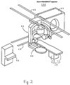
- Figure 2 is a perspective view in which the CT gantry 40 is moved to the CT gantry parking position and the frontal and lateral arms 20 and 30 are moved to the biplane angiographic imaging position.
- the lateral arm 30 can be moved to the biplane angiographic imaging position without interfering with the CT gantry 40. Then, the frontal arm 20 performs angiographic imaging in a frontal plane and the lateral arm 30 performs angiographic imaging in a lateral plane at the biplane angiographic imaging position. Thus, simultaneous angiographic imaging in two planes, frontal and lateral, is achieved.
- Figure 5 is a flow chart of a CT moving process executed by the control apparatus 50.
- Step C1 the operator depresses a frontal/lateral arm parking switch provided on the control apparatus 50.
- Step C2 a decision is made whether the frontal and lateral arms 20 and 30 interfere with the CT gantry 40 or top plate 11 when the frontal and lateral arms 20 and 30 are moved to frontal and lateral arm parking positions which lie in the longitudinal direction of the top plate 11, as shown in Figure 3, and which do not hinder the CT imaging. If interference does not occur, the process goes to Step C3; otherwise to Step C7.
- Step C3 the frontal and lateral arms 20 and 30 are moved to the frontal/lateral arm parking positions shown in Figure 3.
- Step C4 the operator confirms that the frontal and lateral arms 20 and 30 have been moved to the frontal and lateral arm parking positions shown in Figure 3, and then the operator depresses a CT gantry moving switch provided on the control apparatus 50.
- Step C5 decision is made whether the CT gantry 40 interferes with the frontal arm 20, lateral arm 30 or top plate 11 when the CT gantry 40 is moved to a CT imaging position which lies in the longitudinal direction of the top plate 11 as shown in Figure 3. If interference does not occur, the process goes to Step C6; otherwise to Step C7.
- Step C6 the CT gantry 40 is moved to the CT imaging position shown in Figure 3. Then, the process is terminated.
- Step C7 warning is given that the movement is not permissible because of interference. Then, the process is terminated.
- Figure 3 is a perspective view in which the frontal and lateral arms 20 and 30 are moved to the frontal and lateral arm parking positions and the CT gantry 40 is moved to the CT imaging position.
- the CT gantry 40 can be moved to the CT imaging position without interfering with the frontal and lateral arms 20 and 30. Then, CT imaging can be performed by the CT gantry 40 at the CT imaging position.
- the lateral arm 30 for performing angiographic imaging in a lateral plane is provided in addition to the frontal arm 20 and the CT gantry 40, simultaneous angiographic imaging in two planes, frontal and lateral, is possible.
- the CT gantry 40 is retracted to a position not hindering the angiographic imaging and the frontal and lateral arms 20 and 30 are moved to an angiographic imaging position, and when CT imaging is to be performed, the frontal and lateral arms 20 and 30 are retracted to positions not hindering the CT imaging and the CT gantry 40 is moved to a CT imaging position.
- Figure 6 is a perspective view of a biplane angiography/CT apparatus 300 in accordance with a second embodiment of the present invention.
- the biplane angiography/CT apparatus 300 has generally similar configuration to that of the biplane angiography/CT apparatus 100 of the first embodiment, and portions having similar configuration will not be described.
- the present embodiment is configured so that a lateral arm 130 comprised of an X-ray tube 132, an X-ray image receiving device 131 and a lateral C arm 133 horizontally moves in the transverse direction of the top plate 11 along a ceiling rail 135, and a CT gantry 140 comprising an X-ray tube 141 and an X-ray detector 142 horizontally moves in the longitudinally direction of the top plate 11.
- the lateral arm 130 for performing angiographic imaging in a lateral plane is provided in addition to the frontal arm 20 and the CT gantry 140, simultaneous angiographic imaging in two planes, frontal and lateral, is possible.
- the CT gantry 140 is retracted to a position not hindering the angiographic imaging and the frontal and lateral arms 20 and 130 are moved to an angiographic imaging position, and when CT imaging is to be performed, the frontal and lateral arms 20 and 130 are retracted to positions not hindering the CT imaging and the CT gantry 140 is moved to a CT imaging position.
- Figure 7 is a perspective view of a biplane angiography/CT apparatus 400 in accordance with a third embodiment of the present invention.
- the biplane angiography/CT apparatus 400 has generally similar configuration to that of the biplane angiography/CT apparatus 100 of the first embodiment, and identical portions will not be described.
- the present embodiment is configured so that a CT gantry 240 comprising an X-ray tube 241 and an X-ray detector 242 horizontally turns along an arc-like floor rail 246 between a CT gantry parking position, as shown in Figure 7, at which the CT gantry 240 does not collide with the top plate 11 moved in the longitudinal direction, and which is a position apart from the top plate 11 in the transverse direction by a certain distance, and a CT imaging position (not shown) at which CT imaging can be performed.
- the present invention may include an arc-like ceiling rail along which the lateral arm may horizontally turn between a lateral arm parking position and an angiographic imaging position.
Landscapes
- Health & Medical Sciences (AREA)
- Life Sciences & Earth Sciences (AREA)
- Engineering & Computer Science (AREA)
- Medical Informatics (AREA)
- Heart & Thoracic Surgery (AREA)
- Animal Behavior & Ethology (AREA)
- Biophysics (AREA)
- Nuclear Medicine, Radiotherapy & Molecular Imaging (AREA)
- Optics & Photonics (AREA)
- Pathology (AREA)
- Radiology & Medical Imaging (AREA)
- Biomedical Technology (AREA)
- Physics & Mathematics (AREA)
- Molecular Biology (AREA)
- Surgery (AREA)
- High Energy & Nuclear Physics (AREA)
- General Health & Medical Sciences (AREA)
- Public Health (AREA)
- Veterinary Medicine (AREA)
- Pulmonology (AREA)
- Theoretical Computer Science (AREA)
- Vascular Medicine (AREA)
- Dentistry (AREA)
- Oral & Maxillofacial Surgery (AREA)
- Apparatus For Radiation Diagnosis (AREA)
Abstract
Description
Claims (10)
- A biplane angiography/CT apparatus comprising: a top plate for laying a subject; a frontal arm comprising an X-ray tube and an X-ray image receiving device for performing angiographic imaging vertically across the subject laid on said top plate; a lateral arm comprising an X-ray tube and an X-ray image receiving device for performing angiographic imaging horizontally across the subject laid on said top plate; a CT gantry comprising an X-ray tube and an X-ray detector for performing CT imaging on the subject laid on said top plate; and control means for retracting said CT gantry to a position not hindering angiographic imaging and moving said frontal and lateral arms to an angiographic imaging position based on a command by an operator, and for retracting said frontal and lateral arms to positions not hindering CT imaging and moving said CT gantry to a CT imaging position based on a command by the operator.
- The biplane angiography/CT apparatus as defined by claim 1, wherein said control means is provided with a switch for the operator to input the command to retract said CT gantry to the position not hindering the angiographic imaging.
- The biplane angiography/CT apparatus as defined by claim 1 or 2, wherein said control means is provided with a switch for the operator to input the command to move said frontal and lateral arms to the angiographic imaging position.
- The biplane angiography/CT apparatus as defined by claim 1, wherein said control means is provided with a switch for the operator to input the command to retract said frontal and lateral arms to the positions not hindering the CT imaging.
- The biplane angiography/CT apparatus as defined by claim 1 or 2, wherein said control means is provided with a switch for the operator to input the command to move said CT gantry to the CT imaging position.
- A biplane angiography/CT apparatus comprising: a top plate for laying a subject; a frontal arm comprising an X-ray tube and an X-ray image receiving device for performing angiographic imaging vertically across the subject laid on said top plate; a lateral arm comprising an X-ray tube and an X-ray image receiving device for performing angiographic imaging horizontally across the subject laid on said top plate; a CT gantry comprising an X-ray tube and an X-ray detector for performing CT imaging on the subject laid on said top plate; top plate moving means for allowing said top plate to horizontally move in its longitudinal direction; frontal arm swiveling means for allowing said frontal arm to swivel around a certain axis; lateral arm moving means for allowing said lateral arm to move in a certain direction; and CT gantry moving means for allowing said CT gantry to move in a certain direction.
- The biplane angiography/CT apparatus as defined by claim 6, wherein said lateral arm moving means horizontally moves said lateral arm in the longitudinal direction of said top plate, and said CT gantry moving means horizontally moves said CT gantry in the transverse direction of said top plate.
- The biplane angiography/CT apparatus as defined by claim 6, wherein said lateral arm moving means horizontally moves said lateral arm in the transverse direction of said top plate, and said CT gantry moving means horizontally moves said CT gantry in the longitudinal direction of said top plate.
- The biplane angiography/CT apparatus as defined by claim 6, 7 or 8, wherein said lateral arm moving means rotates said lateral arm around the longitudinal direction of said top plate.
- The biplane angiography/CT apparatus as defined by claim 6, 7, 8, 9, or 10, wherein said CT gantry moving means horizontally turns said CT gantry.
Applications Claiming Priority (2)
| Application Number | Priority Date | Filing Date | Title |
|---|---|---|---|
| JP32192899 | 1999-11-12 | ||
| JP32192899A JP2001137221A (en) | 1999-11-12 | 1999-11-12 | Biplane angiography and ct apparatus |
Publications (2)
| Publication Number | Publication Date |
|---|---|
| EP1099409A2 true EP1099409A2 (en) | 2001-05-16 |
| EP1099409A3 EP1099409A3 (en) | 2003-09-17 |
Family
ID=18137992
Family Applications (1)
| Application Number | Title | Priority Date | Filing Date |
|---|---|---|---|
| EP00309924A Withdrawn EP1099409A3 (en) | 1999-11-12 | 2000-11-08 | Combined biplane angiography and CT apparatus |
Country Status (5)
| Country | Link |
|---|---|
| US (1) | US6435713B1 (en) |
| EP (1) | EP1099409A3 (en) |
| JP (1) | JP2001137221A (en) |
| KR (1) | KR20010060301A (en) |
| CN (1) | CN1295821A (en) |
Cited By (2)
| Publication number | Priority date | Publication date | Assignee | Title |
|---|---|---|---|---|
| FR2860137A1 (en) * | 2003-09-26 | 2005-04-01 | Ge Med Sys Global Tech Co Llc | THERAPEUTIC IMAGING SYSTEM, THERAPEUTIC RADIATION IMAGING SYSTEM AND METHOD OF CONTROLLING SUCH A SYSTEM |
| US7983385B2 (en) | 2006-09-29 | 2011-07-19 | Koninklijke Philips Electronics N.V. | Fly-by scanning |
Families Citing this family (37)
| Publication number | Priority date | Publication date | Assignee | Title |
|---|---|---|---|---|
| JP3930216B2 (en) * | 2000-01-07 | 2007-06-13 | ジーイー・メディカル・システムズ・グローバル・テクノロジー・カンパニー・エルエルシー | Angiography / CT system |
| JP2002017712A (en) * | 2000-07-07 | 2002-01-22 | Shimadzu Corp | X-ray equipment |
| JP4737808B2 (en) * | 2000-09-29 | 2011-08-03 | 株式会社東芝 | IVR-CT equipment |
| US6879661B2 (en) * | 2001-03-19 | 2005-04-12 | Konica Corporation | Radiographing apparatus including a control section for establishing a standby mode in a radiographing section |
| DE10211081A1 (en) * | 2002-03-13 | 2003-10-16 | Siemens Ag | X-ray observation and monitoring system for patient in hospital has movable table with conventional X-ray machine at one end and computer tomography at one end |
| EP1347309A3 (en) * | 2002-03-20 | 2012-04-18 | Hitachi, Ltd. | Radiological imaging apparatus and method |
| JP3961464B2 (en) * | 2002-08-14 | 2007-08-22 | 稔 植松 | Radiotherapy compound device |
| DE60303641T2 (en) | 2002-08-14 | 2006-12-14 | Uematsu, Minoru, Kamakura | Arrangement for radiotherapy |
| JP4268791B2 (en) * | 2002-10-16 | 2009-05-27 | 株式会社東芝 | X-ray diagnostic equipment |
| US7130378B2 (en) * | 2003-02-27 | 2006-10-31 | Shimadzu Corporation | Radiographic X-ray device |
| US7412027B2 (en) * | 2004-01-12 | 2008-08-12 | Ge Medical Systems Global Technology Company, Llc | Methods and system for multi-modality imaging |
| JP4703119B2 (en) * | 2004-03-05 | 2011-06-15 | 株式会社東芝 | X-ray diagnostic equipment |
| WO2006064402A2 (en) * | 2004-12-17 | 2006-06-22 | Koninklijke Philips Electronics, N.V. | Gantry system |
| JP2006239253A (en) * | 2005-03-04 | 2006-09-14 | Toshiba Corp | Image processing apparatus and image processing method |
| JP4709600B2 (en) * | 2005-07-15 | 2011-06-22 | 株式会社東芝 | X-ray diagnostic apparatus, imaging angle optimization support apparatus, and program |
| JP4810182B2 (en) * | 2005-10-17 | 2011-11-09 | キヤノン株式会社 | Radiography equipment |
| CN100539948C (en) * | 2005-10-21 | 2009-09-16 | 株式会社东芝 | Medical image processing device and medical image processing method |
| CN100462049C (en) * | 2006-04-21 | 2009-02-18 | 北京思创贯宇科技开发有限公司 | Method of correcting double planar blood vessel 3D reconstructing deviation caused by C-arm bed motion |
| US8190235B2 (en) * | 2008-06-04 | 2012-05-29 | Imris Inc. | System for magnetic resonance and X-Ray imaging |
| WO2010044844A1 (en) * | 2008-10-13 | 2010-04-22 | George Papaioannou | Dynamic biplane roentgen stereophotogrammetric analysis |
| JP5247363B2 (en) | 2008-11-11 | 2013-07-24 | キヤノン株式会社 | X-ray equipment |
| DE102009037478B4 (en) * | 2009-08-13 | 2017-02-02 | Siemens Healthcare Gmbh | 3-D Data Acquisition Method with a Biplan C-arm System with Biplan Acquisition Multiplexing |
| KR100966114B1 (en) | 2009-10-09 | 2010-06-28 | (주) 뉴캐어메디컬시스템 | Thyroid uptake measurement apparatus |
| JP5460270B2 (en) * | 2009-11-30 | 2014-04-02 | 株式会社東芝 | X-ray diagnostic equipment |
| US9687200B2 (en) * | 2010-06-08 | 2017-06-27 | Accuray Incorporated | Radiation treatment delivery system with translatable ring gantry |
| EP3195902B1 (en) | 2010-02-24 | 2019-07-10 | Accuray, Inc. | Gantry image guided radiotherapy system |
| US8536547B2 (en) | 2011-01-20 | 2013-09-17 | Accuray Incorporated | Ring gantry radiation treatment delivery system with dynamically controllable inward extension of treatment head |
| FR2972915B1 (en) * | 2011-03-24 | 2013-04-19 | Gen Electric | MULTIPLAN MEDICAL IMAGING SYSTEM |
| CN103505209B (en) * | 2012-06-27 | 2015-09-30 | 上海西门子医疗器械有限公司 | Medical apparatus and instruments |
| JP5444422B2 (en) * | 2012-07-17 | 2014-03-19 | 株式会社東芝 | Intraoperative medical imaging system |
| KR102033600B1 (en) | 2012-10-19 | 2019-11-11 | 삼성전자주식회사 | Method and apparatus for measuring medical information providing 3-dimensional stereoscopic image |
| EP2945541A1 (en) * | 2013-01-17 | 2015-11-25 | Koninklijke Philips N.V. | Ceiling suspension system |
| EP3086734B1 (en) * | 2013-12-19 | 2018-02-21 | Koninklijke Philips N.V. | Object tracking device |
| US9247920B2 (en) | 2014-02-27 | 2016-02-02 | General Electric Company | System and method for performing bi-plane tomographic acquisitions |
| US10772577B2 (en) * | 2016-02-01 | 2020-09-15 | Epica International, Inc. | Radiological imaging device |
| EP3592237B1 (en) * | 2017-03-09 | 2021-04-14 | Carestream Health, Inc. | Bearing system for cone beam computed tomography |
| JP7395385B2 (en) * | 2019-02-26 | 2023-12-11 | キヤノンメディカルシステムズ株式会社 | Angio CT device |
Family Cites Families (9)
| Publication number | Priority date | Publication date | Assignee | Title |
|---|---|---|---|---|
| JPH01185246A (en) * | 1988-01-19 | 1989-07-24 | Toshiba Corp | X-ray photographing device |
| US5400792A (en) * | 1990-11-20 | 1995-03-28 | Siemens Aktiengesellschaft | Medical diagnostics installation controllable from a central work station |
| JPH0549628A (en) * | 1991-08-29 | 1993-03-02 | Toshiba Corp | X-ray equipment |
| US5748696A (en) * | 1993-11-26 | 1998-05-05 | Kabushiki Kaisha Toshiba | Radiation computed tomography apparatus |
| JPH0984784A (en) * | 1995-09-22 | 1997-03-31 | Hitachi Medical Corp | X-ray inspecting device |
| US5960054A (en) * | 1997-11-26 | 1999-09-28 | Picker International, Inc. | Angiographic system incorporating a computerized tomographic (CT) scanner |
| US6031888A (en) * | 1997-11-26 | 2000-02-29 | Picker International, Inc. | Fluoro-assist feature for a diagnostic imaging device |
| JPH11164829A (en) * | 1997-12-03 | 1999-06-22 | Toshiba Corp | Mountable helical scan CT system |
| DE19853463B4 (en) * | 1998-11-19 | 2005-08-11 | Siemens Ag | Multiple examination arrangement with a variety of imaging systems |
-
1999
- 1999-11-12 JP JP32192899A patent/JP2001137221A/en active Pending
-
2000
- 2000-10-11 US US09/686,225 patent/US6435713B1/en not_active Expired - Fee Related
- 2000-11-08 CN CN00133927A patent/CN1295821A/en active Pending
- 2000-11-08 EP EP00309924A patent/EP1099409A3/en not_active Withdrawn
- 2000-11-10 KR KR1020000066801A patent/KR20010060301A/en not_active Abandoned
Cited By (3)
| Publication number | Priority date | Publication date | Assignee | Title |
|---|---|---|---|---|
| FR2860137A1 (en) * | 2003-09-26 | 2005-04-01 | Ge Med Sys Global Tech Co Llc | THERAPEUTIC IMAGING SYSTEM, THERAPEUTIC RADIATION IMAGING SYSTEM AND METHOD OF CONTROLLING SUCH A SYSTEM |
| US7983385B2 (en) | 2006-09-29 | 2011-07-19 | Koninklijke Philips Electronics N.V. | Fly-by scanning |
| RU2452384C2 (en) * | 2006-09-29 | 2012-06-10 | Конинклейке Филипс Электроникс Н.В. | Scanning in through mode |
Also Published As
| Publication number | Publication date |
|---|---|
| US6435713B1 (en) | 2002-08-20 |
| KR20010060301A (en) | 2001-07-06 |
| JP2001137221A (en) | 2001-05-22 |
| CN1295821A (en) | 2001-05-23 |
| EP1099409A3 (en) | 2003-09-17 |
Similar Documents
| Publication | Publication Date | Title |
|---|---|---|
| US6435713B1 (en) | Biplane angiography/CT apparatus | |
| US6520677B2 (en) | Angiography/CT method and apparatus | |
| US5386453A (en) | Imaging and treatment apparatus having a floor-mounted guiding track | |
| EP0812567A1 (en) | Medical diagnostic and/or therapy apparatus with a swingable patient table top | |
| EP1004271B1 (en) | Support system for use in radiographic imaging equipment | |
| US5627873A (en) | Mini C-arm assembly for mobile X-ray imaging system | |
| US4987585A (en) | X-ray positioner for multi-axis profiling | |
| CN102984877B (en) | X-ray device with the capture apparatus being maintained on supporting arm | |
| KR102757751B1 (en) | System and method for integrated surgical table | |
| US20080189859A1 (en) | Automatic Retractable Floor System for a Rotating Gantry | |
| US20140177799A1 (en) | X-ray imaging apparatus | |
| US11083420B2 (en) | Robotic operating table and hybrid operating system | |
| JP2018500055A (en) | System and method for integrated operating table icons | |
| JP2010214126A (en) | Mobile radiography apparatus | |
| JPH0871062A (en) | X-ray diagnostic device | |
| KR20220016205A (en) | CT imaging device | |
| JP2011512986A (en) | Method and configuration for mobile imaging system | |
| CN101278840A (en) | X-ray photographic equipment | |
| EP3975854B1 (en) | Ct imaging apparatus | |
| CN117466080A (en) | Cable guide for a computed tomography installation | |
| JPH0127737B2 (en) | ||
| US20050070792A1 (en) | Therapeutic imaging system, and radiation therapeutic imaging system and method of controlling it | |
| JP3767910B2 (en) | X-ray diagnostic equipment | |
| JP3518573B2 (en) | X-ray inspection equipment | |
| WO2014198869A1 (en) | Ceiling suspension system |
Legal Events
| Date | Code | Title | Description |
|---|---|---|---|
| PUAI | Public reference made under article 153(3) epc to a published international application that has entered the european phase |
Free format text: ORIGINAL CODE: 0009012 |
|
| AK | Designated contracting states |
Kind code of ref document: A2 Designated state(s): AT BE CH CY DE DK ES FI FR GB GR IE IT LI LU MC NL PT SE TR |
|
| AX | Request for extension of the european patent |
Free format text: AL;LT;LV;MK;RO;SI |
|
| PUAL | Search report despatched |
Free format text: ORIGINAL CODE: 0009013 |
|
| AK | Designated contracting states |
Kind code of ref document: A3 Designated state(s): AT BE CH CY DE DK ES FI FR GB GR IE IT LI LU MC NL PT SE TR |
|
| AX | Request for extension of the european patent |
Extension state: AL LT LV MK RO SI |
|
| RIC1 | Information provided on ipc code assigned before grant |
Ipc: 7A 61B 6/10 B Ipc: 7A 61B 6/03 B Ipc: 7A 61B 6/00 A |
|
| AKX | Designation fees paid | ||
| REG | Reference to a national code |
Ref country code: DE Ref legal event code: 8566 |
|
| STAA | Information on the status of an ep patent application or granted ep patent |
Free format text: STATUS: THE APPLICATION IS DEEMED TO BE WITHDRAWN |
|
| 18D | Application deemed to be withdrawn |
Effective date: 20040318 |