EP1099226B1 - X-ray focusing apparatus - Google Patents
X-ray focusing apparatus Download PDFInfo
- Publication number
- EP1099226B1 EP1099226B1 EP99934838A EP99934838A EP1099226B1 EP 1099226 B1 EP1099226 B1 EP 1099226B1 EP 99934838 A EP99934838 A EP 99934838A EP 99934838 A EP99934838 A EP 99934838A EP 1099226 B1 EP1099226 B1 EP 1099226B1
- Authority
- EP
- European Patent Office
- Prior art keywords
- ray
- focusing device
- target
- mirror
- ray focusing
- Prior art date
- Legal status (The legal status is an assumption and is not a legal conclusion. Google has not performed a legal analysis and makes no representation as to the accuracy of the status listed.)
- Expired - Lifetime
Links
Images



Classifications
-
- G—PHYSICS
- G21—NUCLEAR PHYSICS; NUCLEAR ENGINEERING
- G21K—HANDLING OF PARTICLES OR IONISING RADIATION NOT OTHERWISE PROVIDED FOR; IRRADIATION DEVICES; GAMMA RAY OR X-RAY MICROSCOPES
- G21K1/00—Arrangements for handling particles or ionising radiation, e.g. focusing or moderating
- G21K1/06—Arrangements for handling particles or ionising radiation, e.g. focusing or moderating using diffraction, refraction or reflection, e.g. monochromators
Definitions
- This invention relates to X-ray focusing devices for use with X-ray generators and in particular to X-ray focusing devices which utilise capillary and polycapillary lenses in combination with X-ray focusing mirrors for the close coupled focusing of X-ray beams.
- X-ray generators produce X-ray beams which have a relatively large focal spot or line which requires that the generator utilises a relatively small aperture to restrict beam diameter and divergence.
- the use of small apertures results in a large loss of X-ray intensity.
- X-ray focusing mirrors may be used in order to focus and thereby increase the intensity of the beam from an X-ray generator.
- An example of such a focusing mirror is that distributed by Bede Scientific Instruments Ltd under the Trade Mark "Micromirror”. "Micromirrors" are now in commercial production and are being used in X-ray generators. The brightness achieved by using the "Micromirror” is comparable to that given by rotating anode generators with total reflection optics.
- This focusing mirror comprises a cylindrical body having an axially symmetrical passage extending therethrough. There is an aperture at each end of the body which communicates with the passage.
- the passage has a profile which may be ellipsoidal or paraboloidal in longitudinal section, depending on requirements.
- An ellipsoidal profile produces a focused beam with varying divergence and focused spot size, while a paraboloidal profile produces an almost parallel, essentially non-divergent beam.
- the interior reflecting surface is coated in an exceptionally smooth coating of gold or similar in order to provide specular reflectivity.
- the mirror is made of nickel and is of the order of 30mm in length. The outside diameter of the mirror is typically 6mm.
- the entry aperture is generally smaller than the exit aperture.
- a capillary lens conventionally comprises a number of capillary tubes bundled together.
- a capillary lens is capable of focusing X-ray radiation to a small diameter spot, but suffers from the disadvantage that the focused beam has relatively high divergence.
- an X-ray mirror can produce a beam of relatively low divergence.
- a single X-ray focusing mirror is used to focus the source beam and thus produce a gain in intensity from the X-ray generator to the specimen.
- X-ray generators provide X-ray beams which have a relatively large focal spot and therefore even when focused by the X-ray focusing mirror the beam will not be as intense as it can be.
- tests have shown that the smaller the dimension of the focal spot the greater increase in gain there will be through the X-ray focusing mirror.
- the present invention aims to provide apparatus which in combination will provide an input focal point at the entry aperture of the X-ray focusing mirror which has a diameter as close as possible to zero, thereby maximising the gain through the X-ray focusing mirror to the target specimen.
- an X-ray focusing device comprising a capillary waveguide arranged on a first axis closely coupled to an X-ray focusing mirror, whereby the mirror comprises an interior reflecting surface having a rotational axis of symmetry on a second axis, said first and second axes being substantially collinear.
- close coupling involves arranging the components of the focusing device such that the separation between them is of the order of magnitude of the length of each component or less, preferably less than 50 mm, most preferably less than 10 mm.
- said interior reflecting surface is ellipsoidal, paraboloidal or conical in longitudinal section.
- said capillary waveguide comprises one or more tapered capillaries arranged symmetrically about said first axis.
- the angle of taper of said tapered capillaries is less than 10 mrad.
- the capillary waveguide is arranged to produce a focused X-ray beam of less than 10 ⁇ m diameter.
- the capillary lens comprises a single tapered capillary having an internal profile adapted to reduce the diameter of the focal spot of an X-ray source.
- an X-ray focusing device comprising a polycapillary lens arranged on a first axis closely coupled to an X-ray focusing mirror, whereby the mirror comprises an interior reflecting surface having a rotational axis of symmetry on a second axis, said first and second axes being substantially collinear.
- said interior reflecting surface is ellipsoidal, paraboloidal or conical in longitudinal section.
- said polycapillary lens comprises a plurality of tapered capillaries arranged such that both the diameter of the focal spot of an X-ray source and the angular divergence of the X-rays are reduced.
- said capillaries comprises fibres having internal diameters of less than 10 ⁇ m, most preferably less than 2 ⁇ m.
- said polycapillary lens comprises between 10 and 500, most preferably between 50 and 200 tapered capillaries.
- said polycapillary lens is arranged such that its overall diameter first increases and then decreases with increasing distance from the X-ray source.
- said mirror is moveable in position relative to said waveguide.
- said device further comprises a guide means for guiding said mirror in a direction parallel to the second axis, and adjustment means for adjusting the spacing of the waveguide and the mirror.
- the device also comprises angular adjustment means adapted to allow angular adjustment of the mirror.
- said mirror is fixed in position relative to said waveguide.
- an X-ray focusing device comprising a polycapillary lens arranged on a first axis closely coupled to a planar or non-planar X-ray target of an X-ray generator, said polycapillary lens comprising a plurality of tapered capillaries arranged such that the input end of each capillary is arranged substantially normal to the adjacent portion of said X-ray target.
- the polycapillary lens may be closely coupled to an X-ray focusing mirror at its end remote from the target, in accordance with the first or second aspects of the invention.
- said polycapillary lens is arranged such that its overall diameter first increases and then decreases with increasing distance from the X-ray source.
- an X-ray generating device comprising an annular electron source arranged about a tapered or conical X-ray target closely coupled to a polycapillary lens or an X-ray focusing mirror.
- the X-ray target may be coupled to a polycapillary lens, which is itself closely coupled to an X-ray focusing mirror at its end remote from the target, in accordance with the first or second aspects of the invention.
- an X-ray focusing device comprising a substantially hemispherical X-ray target closely coupled to a polycapillary lens or an X-ray focusing mirror, the target comprising a plurality of channels axially orientated towards the hemispherical centre.
- the device is positioned such that the electron source is at the hemispherical centre.
- the X-ray target may be coupled to a polycapillary lens, which is itself closely coupled to an X-ray focusing mirror at its end remote from the target, in accordance with the first or second aspects of the invention.
- the lens or mirror is arranged such that the angle of collection of the lens or mirror is the same as the angle subtended by the hemispherical target at the hemispherical centre.
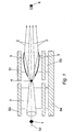
- a first embodiment of the present invention is shown, wherein an X-ray generator (not shown) produces an X-ray source 1 on a target of a particular dimension.
- a single tapered capillary (STC) 3 acts as a waveguide and is positioned close to the source 1 to collect the X-rays from the source 1.
- the STC 3 produces a "virtual" focus 4 at the exit aperture of the STC.
- An X-ray focusing mirror 5 is closely coupled to the "virtual" focus point 4 to produce a focused X-ray beam 2 which is focused to a focal point 6.
- the schematic arrangements for the housing of the STC lens 3 and mirror 5 can also be seen.
- the STC lens 3 and mirror 5 are aligned with each other and are fixed within separate cylindrical housings 50,51.
- the housings 50,51 may further be contained in an outer housing (not shown) which may be partially evacuated.
- the apparatus allows alignment of the mirror 5 relative to the STC lens 3 along the beam axis 52 by means of a control mechanism 53. Alignment of the whole assembly relative to the X-ray source 1 is possible by means of a control mechanism 54.
- the control mechanisms 53,54 allow fine adjustment of the position of the housing 51 and also the whole assembly in the x, y, and z directions so that the axis of the mirror 5 is accurately aligned with the X-ray source 1.
- the mechanisms 50,51 may comprise any suitable mechanisms which permit fine translational adjustment, such as lead screws or Vernier controls.
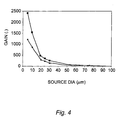
- the gain in intensity through the X-ray focusing mirror 5 increases significantly, especially when the diameter of the focal spot 4 is less than 25 ⁇ m. Whilst there is a significant loss of intensity through the STC lens 3, tests have shown that the increased gain in intensity from the X-ray focusing mirror 5 is higher than the losses in the STC lens 3.
- the use of an STC lens 3 also allows the X-ray generator to run with a larger focal spot at the X-ray source (typically 100 ⁇ m) and at higher powers than are presently possible, giving a ten fold increase in X-ray brightness.
- the combination of increased power loading and increased mirror efficiency more than balances the losses in the STC lens 3 and produces a net gain of one order of magnitude in intensity when compared to the situation in which the X-ray focusing mirror 5 alone is coupled directly to the X-ray source of the X-ray generator. It is envisaged that the X-ray focusing mirrors may be used with standard sealed tube and rotating anode sources.
- the STC has a tapering internal profile such that the focal spot dimensions of the X-ray source 1 are reduced.
- the entry diameter of the capillary is of the same magnitude as the diameter of the source, typically 100 ⁇ m, while the exit diameter of the capillary should be as small as possible, typically 10 ⁇ m or less.
- the angle of convergence of the capillary should be kept as small as possible to minimise X-ray losses through the capillary walls. Typically the angle of convergence should be 10 mrad or less.
- the angle of convergence may be uniform (ie linear tapering) or the longitudinal profile may be ellipsoidal.
- the entry aperture of the mirror 5 is optimally placed at a distance from the exit aperture of the capillary which is equal to the input focal length of the mirror.
- the input focal length of the reflecting mirror should be a minimum.
- the use of the mirror 5 and the capillary 3 in combination leads to a net gain in the brightness of the X-ray beam at the focus 6 of the mirror 5 since the mirror focuses much more efficiently with smaller focal spot 4 dimensions.
- the use of the mirror 5 and the capillary 3 in combination allows a larger diameter X-ray source to be used, leading to a higher power loading of the X-ray target and a higher total energy delivered to the focus 6 of the mirror 5.
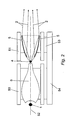
- a second embodiment of the present invention is shown, wherein an X-ray generator (not shown) produces an X-ray source 1 on a target.
- a "bottle-shaped" tapered polycapillary (TPC) lens 6 acts to both reduce the spatial size of the focal spot from the X-ray source 1 and to reduce the angular divergence of the X-rays.
- the TPC lens 6 is close coupled to an X-ray focusing mirror 5 and produces a "virtual" focus 4, which is then focused by the X-ray focusing mirror 5 as a focused X-ray beam 2 to the specimen (not shown).
- This second embodiment uses similar housings and adjustment means to those shown in Fig. 1, and are not described further.
- the gain of this second embodiment is produced by three effects, namely:
- the approximate gains from the second embodiment are a four fold increase from the increased tube target power loading, a three fold increase due to the smaller, lower divergence spot 4 delivered to the X-ray focusing mirror 5, and a five fold increase due to the higher solid angle of collection on the TPC lens 6 (allowing for losses in the TPC lens 6).
- the source 1 is about 100 ⁇ m in diameter, while the virtual focus is less than 10 ⁇ m in diameter.
- the TPC lens comprises about 100 fibres arranged in a bundle with an overall diameter of between 100 and 200 ⁇ m at entry, increasing to between 200 and 400 ⁇ m at an intermediate point and tapering to 2 to 15 ⁇ m at exit.
- Each individual fibre making up the TPC has an inner diameter which varies from 1 to 40 ⁇ m.
- Polycapillary lenses comprised of individual capillaries with diameters of around 10 ⁇ m are commercially available now. With improvements to current technology it is reasonable to expect that capillary diameters of less than 10 ⁇ m can be achieved.
- a third embodiment of the present invention is shown, wherein a novel design of X-ray generator 10 is closely coupled to an X-ray optic in the form of a TPC lens 6 similar to that shown in the second embodiment of the present invention.
- the X-ray generator 10 comprises an electron gun 11 producing accelerated electron beams 22 through a Wehnelt grid 13 and a transmission target 12 thus producing X-rays 70.
- the target 12 has a surface which is curved in two perpendicular directions. It is to be understood that the surface may be curved in only one axis or indeed may be substantially planar or composed of a number of planar or curved portions in the form of a polyhedron.
- the tapered polycapillary lens is close coupled to the target 12, and a gas flow 14 is introduced between the target 12 and the TPC lens 6 in order to provide cooling for the target 12.
- a possible variation of this third embodiment would be the direct coupling of the X-ray generator 10 to an X-ray focusing mirror 5, which would also deliver significant gains.
- the X-ray generator 10 of the third embodiment is located within a housing 56 and powered via a high voltage connector 55.
- the X-ray generator 10 is provided with both insulator plates 58, which may be manufactured from either glass or a ceramic material, and also an insulating potting compound 57 located between the housing 56 and the X-ray generator 10.
- the TPC lens 6 is located within an optics housing 59 adjacent the generator housing 56.
- the TPC lens 6 is held within the optics housing 59 by way of a number of adjustable mountings 60, which permit the position of the TPC lens 6 to be adjusted in the x, y, and z directions so that the lens 6 is accurately aligned with the X-ray source.
- This third embodiment produces gain by spreading the X-ray source over a much greater surface area which thereby allows for much higher power loading, whilst still retaining the gain of the X-ray optic 6. In this way it is possible to produce extremely simple, compact high power X-ray generators.
- the X-ray optic 6 can be tailored to deliver a beam 2 of varying spatial and angular characteristics, which may then be coupled to an X-ray focusing mirror 5 in the manner described in the first and second embodiments.
- a point source at a given distance from an x-ray optic such as the polycapillary lens
- an extended source next to the optic provided the solid angle of collection is the same. Whilst extending the source in this way does not increase the efficiency of the optic per se, it allows each part of the extended source to operate at a power loading (power per unit area) of the same order of magnitude as the power loading of a smaller "point" source. Because the extended source has a larger area allowing a total power of typically several kW, compared to a typical point source of 25 W, the generator can run at much higher operating powers.
- the target 12 is shaped as part of a hemisphere.
- Other geometries are possible, for example the target may be shaped as a truncated cone, as shown in Fig. 5.
- the entry aperture of the PCL has a shape which corresponds to that of the target.
- the embodiment of Fig. 5 uses an annular filament 30 as an electron source.
- the filament 30 fires electrons 31 onto a tapered target 32 which is shown as a truncated cone which is encircled by the coaxial circular annular filament 30.
- the optic (PCL or X-ray focusing mirror) 6 is close coupled to the target 32, which may be cooled by water 33.
- the filament 31 and target 32 are located in a vacuum 65 which is enclosed by an annular ceramic disk 63, whilst the generated X-rays 70 exit through an annular beryllium exit window 64 in order to maintain the vacuum 65.
- the generator is located within a housing 62 and is powered via a high voltage connector 61.
- the optic 6 is also housed in an optics housing 66 which is similar to those described in the other embodiments, with adjustable mountings 60 for adjustment of the optic 6 in the x, y, and z directions.
- Fig. 6 The embodiment of Fig. 6 is located in a housing 56 such as that described in Fig. 3, and uses as a target a hemispherical microchannel plate 40 coated with target material and held in place by a plate holder 67.
- the plate 40 comprises a number of capillaries or channels 41, seen more clearly in Fig. 7, which themselves form targets and direct the x-rays 70 caused by the incidence of the electrons on the surface of the target towards the close coupled optic 6.
- the outer surface 42 only of the plate 40 may be coated with target material.
- a curved beryllium window 68 is attached to the housing 56.
Landscapes
- Physics & Mathematics (AREA)
- Spectroscopy & Molecular Physics (AREA)
- Engineering & Computer Science (AREA)
- General Engineering & Computer Science (AREA)
- High Energy & Nuclear Physics (AREA)
- X-Ray Techniques (AREA)
- Analysing Materials By The Use Of Radiation (AREA)
- Apparatus For Radiation Diagnosis (AREA)
- Radiation-Therapy Devices (AREA)
Abstract
Description
- This invention relates to X-ray focusing devices for use with X-ray generators and in particular to X-ray focusing devices which utilise capillary and polycapillary lenses in combination with X-ray focusing mirrors for the close coupled focusing of X-ray beams.
- The majority of X-ray generators produce X-ray beams which have a relatively large focal spot or line which requires that the generator utilises a relatively small aperture to restrict beam diameter and divergence. However, the use of small apertures results in a large loss of X-ray intensity.
- It is known that X-ray focusing mirrors may be used in order to focus and thereby increase the intensity of the beam from an X-ray generator. An example of such a focusing mirror is that distributed by Bede Scientific Instruments Ltd under the Trade Mark "Micromirror". "Micromirrors" are now in commercial production and are being used in X-ray generators. The brightness achieved by using the "Micromirror" is comparable to that given by rotating anode generators with total reflection optics.
- This focusing mirror comprises a cylindrical body having an axially symmetrical passage extending therethrough. There is an aperture at each end of the body which communicates with the passage. The passage has a profile which may be ellipsoidal or paraboloidal in longitudinal section, depending on requirements. An ellipsoidal profile produces a focused beam with varying divergence and focused spot size, while a paraboloidal profile produces an almost parallel, essentially non-divergent beam. The interior reflecting surface is coated in an exceptionally smooth coating of gold or similar in order to provide specular reflectivity. Typically the mirror is made of nickel and is of the order of 30mm in length. The outside diameter of the mirror is typically 6mm. The entry aperture is generally smaller than the exit aperture.
- It is known to use capillary lenses to focus X-rays. A capillary lens conventionally comprises a number of capillary tubes bundled together. A capillary lens is capable of focusing X-ray radiation to a small diameter spot, but suffers from the disadvantage that the focused beam has relatively high divergence. In contrast an X-ray mirror can produce a beam of relatively low divergence.
- In conventional use, a single X-ray focusing mirror is used to focus the source beam and thus produce a gain in intensity from the X-ray generator to the specimen. However X-ray generators provide X-ray beams which have a relatively large focal spot and therefore even when focused by the X-ray focusing mirror the beam will not be as intense as it can be. In addition, tests have shown that the smaller the dimension of the focal spot the greater increase in gain there will be through the X-ray focusing mirror. Thus, the present invention aims to provide apparatus which in combination will provide an input focal point at the entry aperture of the X-ray focusing mirror which has a diameter as close as possible to zero, thereby maximising the gain through the X-ray focusing mirror to the target specimen.
- According to a first aspect of the present invention there is provided an X-ray focusing device comprising a capillary waveguide arranged on a first axis closely coupled to an X-ray focusing mirror, whereby the mirror comprises an interior reflecting surface having a rotational axis of symmetry on a second axis, said first and second axes being substantially collinear.
- It will be understood to those skilled in the art that close coupling involves arranging the components of the focusing device such that the separation between them is of the order of magnitude of the length of each component or less, preferably less than 50 mm, most preferably less than 10 mm.
- Preferably said interior reflecting surface is ellipsoidal, paraboloidal or conical in longitudinal section.
- Preferably said capillary waveguide comprises one or more tapered capillaries arranged symmetrically about said first axis. Preferably the angle of taper of said tapered capillaries is less than 10 mrad.
- Preferably the capillary waveguide is arranged to produce a focused X-ray beam of less than 10 µm diameter.
- According to a preferred embodiment the capillary lens comprises a single tapered capillary having an internal profile adapted to reduce the diameter of the focal spot of an X-ray source.
- According to a second aspect of the present invention there is provided an X-ray focusing device comprising a polycapillary lens arranged on a first axis closely coupled to an X-ray focusing mirror, whereby the mirror comprises an interior reflecting surface having a rotational axis of symmetry on a second axis, said first and second axes being substantially collinear.
- Preferably said interior reflecting surface is ellipsoidal, paraboloidal or conical in longitudinal section.
- Preferably said polycapillary lens comprises a plurality of tapered capillaries arranged such that both the diameter of the focal spot of an X-ray source and the angular divergence of the X-rays are reduced.
- Preferably said capillaries comprises fibres having internal diameters of less than 10 µm, most preferably less than 2 µm.
- Preferably said polycapillary lens comprises between 10 and 500, most preferably between 50 and 200 tapered capillaries.
- Preferably said polycapillary lens is arranged such that its overall diameter first increases and then decreases with increasing distance from the X-ray source.
- Preferably, said mirror is moveable in position relative to said waveguide. Preferably, said device further comprises a guide means for guiding said mirror in a direction parallel to the second axis, and adjustment means for adjusting the spacing of the waveguide and the mirror. Preferably, the device also comprises angular adjustment means adapted to allow angular adjustment of the mirror. Alternatively, said mirror is fixed in position relative to said waveguide.
- According to a third aspect of the present invention there is provided an X-ray focusing device comprising a polycapillary lens arranged on a first axis closely coupled to a planar or non-planar X-ray target of an X-ray generator, said polycapillary lens comprising a plurality of tapered capillaries arranged such that the input end of each capillary is arranged substantially normal to the adjacent portion of said X-ray target. The polycapillary lens may be closely coupled to an X-ray focusing mirror at its end remote from the target, in accordance with the first or second aspects of the invention.
- Preferably said polycapillary lens is arranged such that its overall diameter first increases and then decreases with increasing distance from the X-ray source.
- According to a fourth aspect of the present invention there is provided an X-ray generating device comprising an annular electron source arranged about a tapered or conical X-ray target closely coupled to a polycapillary lens or an X-ray focusing mirror. The X-ray target may be coupled to a polycapillary lens, which is itself closely coupled to an X-ray focusing mirror at its end remote from the target, in accordance with the first or second aspects of the invention.
- According to a fifth aspect of the present invention there is provided an X-ray focusing device comprising a substantially hemispherical X-ray target closely coupled to a polycapillary lens or an X-ray focusing mirror, the target comprising a plurality of channels axially orientated towards the hemispherical centre. Preferably the device is positioned such that the electron source is at the hemispherical centre. The X-ray target may be coupled to a polycapillary lens, which is itself closely coupled to an X-ray focusing mirror at its end remote from the target, in accordance with the first or second aspects of the invention. Preferably the lens or mirror is arranged such that the angle of collection of the lens or mirror is the same as the angle subtended by the hemispherical target at the hemispherical centre.
- Embodiments of the invention will now be described, by way of example only, with reference to the accompanying figures, where:
- Fig. 1 shows a first embodiment of the present invention, wherein a Single Tapered Capillary lens (STC) is closely coupled to a X-ray focusing mirror;
- Fig. 2 shows a second embodiment of the present invention, wherein a specifically profiled Tapered Polycapillary lens (TPC) is closely coupled to a X-ray focusing mirror;
- Fig. 3 shows a third embodiment of the present invention, wherein a novel X-ray generator is closely coupled to a TPC;
- Fig. 4 is a graph showing the variation in gain against the reduction in diameter of the source beam;
- Fig. 5 shows a particular embodiment of the apparatus of Fig. 3 using a tapered conical target;
- Fig. 6 shows a particular embodiment of the apparatus of Fig. 3 using a hemispherical microchannel target; and
- Fig. 7 shows a section along line VII-VII of the microchannel target of the apparatus of Fig. 6.
- With reference to Fig. 1, a first embodiment of the present invention is shown, wherein an X-ray generator (not shown) produces an X-ray source 1 on a target of a particular dimension. A single tapered capillary (STC) 3 acts as a waveguide and is positioned close to the source 1 to collect the X-rays from the source 1. The STC 3 produces a "virtual"
focus 4 at the exit aperture of the STC. AnX-ray focusing mirror 5 is closely coupled to the "virtual"focus point 4 to produce a focusedX-ray beam 2 which is focused to afocal point 6. - The schematic arrangements for the housing of the
STC lens 3 andmirror 5 can also be seen. TheSTC lens 3 andmirror 5 are aligned with each other and are fixed within separatecylindrical housings housings mirror 5 relative to theSTC lens 3 along thebeam axis 52 by means of acontrol mechanism 53. Alignment of the whole assembly relative to the X-ray source 1 is possible by means of acontrol mechanism 54. - The
control mechanisms housing 51 and also the whole assembly in the x, y, and z directions so that the axis of themirror 5 is accurately aligned with the X-ray source 1. Themechanisms - As shown in Fig. 4, as the diameter of the
focal spot 4 decreases, the gain in intensity through theX-ray focusing mirror 5 increases significantly, especially when the diameter of thefocal spot 4 is less than 25 µm. Whilst there is a significant loss of intensity through theSTC lens 3, tests have shown that the increased gain in intensity from theX-ray focusing mirror 5 is higher than the losses in theSTC lens 3. In addition, the use of anSTC lens 3 also allows the X-ray generator to run with a larger focal spot at the X-ray source (typically 100 µm) and at higher powers than are presently possible, giving a ten fold increase in X-ray brightness. - The combination of increased power loading and increased mirror efficiency more than balances the losses in the
STC lens 3 and produces a net gain of one order of magnitude in intensity when compared to the situation in which theX-ray focusing mirror 5 alone is coupled directly to the X-ray source of the X-ray generator. It is envisaged that the X-ray focusing mirrors may be used with standard sealed tube and rotating anode sources. - The STC has a tapering internal profile such that the focal spot dimensions of the X-ray source 1 are reduced. The entry diameter of the capillary is of the same magnitude as the diameter of the source, typically 100 µm, while the exit diameter of the capillary should be as small as possible, typically 10 µm or less. The angle of convergence of the capillary should be kept as small as possible to minimise X-ray losses through the capillary walls. Typically the angle of convergence should be 10 mrad or less. The angle of convergence may be uniform (ie linear tapering) or the longitudinal profile may be ellipsoidal.
- The entry aperture of the
mirror 5 is optimally placed at a distance from the exit aperture of the capillary which is equal to the input focal length of the mirror. The input focal length of the reflecting mirror should be a minimum. - The use of the
mirror 5 and thecapillary 3 in combination leads to a net gain in the brightness of the X-ray beam at thefocus 6 of themirror 5 since the mirror focuses much more efficiently with smallerfocal spot 4 dimensions. In addition the use of themirror 5 and thecapillary 3 in combination allows a larger diameter X-ray source to be used, leading to a higher power loading of the X-ray target and a higher total energy delivered to thefocus 6 of themirror 5. - With reference to Fig. 2, a second embodiment of the present invention is shown, wherein an X-ray generator (not shown) produces an X-ray source 1 on a target. A "bottle-shaped" tapered polycapillary (TPC)
lens 6 acts to both reduce the spatial size of the focal spot from the X-ray source 1 and to reduce the angular divergence of the X-rays. TheTPC lens 6 is close coupled to anX-ray focusing mirror 5 and produces a "virtual"focus 4, which is then focused by theX-ray focusing mirror 5 as afocused X-ray beam 2 to the specimen (not shown). This second embodiment uses similar housings and adjustment means to those shown in Fig. 1, and are not described further. - The gain of this second embodiment is produced by three effects, namely:
- (i) a higher power loading on the X-ray generator target (not shown) due to the larger allowable X-ray generator tube focal spot 1,
- (ii) a higher solid angle of collection of the
X-ray beam 2 from theTPC lens 6 than from theX-ray focusing mirror 5 alone, and - (iii) a lower divergence of the rays ("natural" divergence from a capillary is around 0.4°) and a smaller focal spot dimension which maximises the gain through the
X-ray focusing mirror 5. - The approximate gains from the second embodiment are a four fold increase from the increased tube target power loading, a three fold increase due to the smaller,
lower divergence spot 4 delivered to theX-ray focusing mirror 5, and a five fold increase due to the higher solid angle of collection on the TPC lens 6 (allowing for losses in the TPC lens 6). - Typically the source 1 is about 100 µm in diameter, while the virtual focus is less than 10 µm in diameter. In one example the TPC lens comprises about 100 fibres arranged in a bundle with an overall diameter of between 100 and 200 µm at entry, increasing to between 200 and 400 µm at an intermediate point and tapering to 2 to 15 µm at exit. Each individual fibre making up the TPC has an inner diameter which varies from 1 to 40 µm. Polycapillary lenses comprised of individual capillaries with diameters of around 10 µm are commercially available now. With improvements to current technology it is reasonable to expect that capillary diameters of less than 10 µm can be achieved.
- With reference to Fig.3, a third embodiment of the present invention is shown, wherein a novel design of
X-ray generator 10 is closely coupled to an X-ray optic in the form of aTPC lens 6 similar to that shown in the second embodiment of the present invention. TheX-ray generator 10 comprises anelectron gun 11 producing acceleratedelectron beams 22 through aWehnelt grid 13 and atransmission target 12 thus producingX-rays 70. Thetarget 12 has a surface which is curved in two perpendicular directions. It is to be understood that the surface may be curved in only one axis or indeed may be substantially planar or composed of a number of planar or curved portions in the form of a polyhedron. The tapered polycapillary lens is close coupled to thetarget 12, and agas flow 14 is introduced between thetarget 12 and theTPC lens 6 in order to provide cooling for thetarget 12. A possible variation of this third embodiment would be the direct coupling of theX-ray generator 10 to anX-ray focusing mirror 5, which would also deliver significant gains. - The
X-ray generator 10 of the third embodiment is located within ahousing 56 and powered via ahigh voltage connector 55. To provide insulation, theX-ray generator 10 is provided with bothinsulator plates 58, which may be manufactured from either glass or a ceramic material, and also an insulatingpotting compound 57 located between thehousing 56 and theX-ray generator 10. - The
TPC lens 6 is located within anoptics housing 59 adjacent thegenerator housing 56. TheTPC lens 6 is held within theoptics housing 59 by way of a number ofadjustable mountings 60, which permit the position of theTPC lens 6 to be adjusted in the x, y, and z directions so that thelens 6 is accurately aligned with the X-ray source. - This third embodiment produces gain by spreading the X-ray source over a much greater surface area which thereby allows for much higher power loading, whilst still retaining the gain of the
X-ray optic 6. In this way it is possible to produce extremely simple, compact high power X-ray generators. In addition, theX-ray optic 6 can be tailored to deliver abeam 2 of varying spatial and angular characteristics, which may then be coupled to anX-ray focusing mirror 5 in the manner described in the first and second embodiments. - In the apparatus according to the third embodiment a point source at a given distance from an x-ray optic, such as the polycapillary lens, can be replaced by an extended source next to the optic, provided the solid angle of collection is the same. Whilst extending the source in this way does not increase the efficiency of the optic per se, it allows each part of the extended source to operate at a power loading (power per unit area) of the same order of magnitude as the power loading of a smaller "point" source. Because the extended source has a larger area allowing a total power of typically several kW, compared to a typical point source of 25 W, the generator can run at much higher operating powers.
- In the example of Fig. 3 the
target 12 is shaped as part of a hemisphere. Other geometries are possible, for example the target may be shaped as a truncated cone, as shown in Fig. 5. The entry aperture of the PCL has a shape which corresponds to that of the target. - The embodiment of Fig. 5 uses an
annular filament 30 as an electron source. Thefilament 30fires electrons 31 onto a taperedtarget 32 which is shown as a truncated cone which is encircled by the coaxial circularannular filament 30. The optic (PCL or X-ray focusing mirror) 6 is close coupled to thetarget 32, which may be cooled bywater 33. Thefilament 31 andtarget 32 are located in avacuum 65 which is enclosed by an annularceramic disk 63, whilst the generatedX-rays 70 exit through an annularberyllium exit window 64 in order to maintain thevacuum 65. - As with the previous embodiments, the generator is located within a
housing 62 and is powered via ahigh voltage connector 61. Theoptic 6 is also housed in anoptics housing 66 which is similar to those described in the other embodiments, withadjustable mountings 60 for adjustment of theoptic 6 in the x, y, and z directions. - The embodiment of Fig. 6 is located in a
housing 56 such as that described in Fig. 3, and uses as a target ahemispherical microchannel plate 40 coated with target material and held in place by aplate holder 67. Theplate 40 comprises a number of capillaries orchannels 41, seen more clearly in Fig. 7, which themselves form targets and direct thex-rays 70 caused by the incidence of the electrons on the surface of the target towards the close coupledoptic 6. Alternatively theouter surface 42 only of theplate 40 may be coated with target material. So as to maintain the vacuum within thetube housing 56, acurved beryllium window 68 is attached to thehousing 56. - These and other modifications and improvements can be incorporated without departing from the scope of the invention as defined by the accompanying claims.
Claims (26)
- An X-ray focusing device comprising a waveguide arranged on a first axis closely coupled to an X-ray focusing mirror, whereby the mirror comprises an interior reflecting surface having a rotational axis of symmetry on a second axis, said first and second axes being substantially collinear.
- An X-ray focusing device according to Claim 1, wherein said waveguide is a capillary waveguide comprising one or more tapered capillaries arranged symmetrically about said first axis.
- An X-ray focusing device according to Claim 2, wherein the angle of taper of said tapered capillaries is less than 10 mrad.
- An X-ray focusing device according to either Claim 2 or Claim 3, wherein the capillary waveguide is arranged to produce a focused X-ray beam of less than 10 µm diameter.
- An X-ray focusing device according to Claim 1, wherein said waveguide is a polycapillary lens.
- An X-ray focusing device according to Claim 5, wherein said polycapillary lens comprises a plurality of tapered capillaries arranged such that both the diameter of the focal spot of an X-ray source and the angular divergence of the X-rays are reduced at a sample point.
- An X-ray focusing device according to Claim 6, wherein said capillaries comprise tubes having internal diameters of less than 10 µm.
- An X-ray focusing device according to Claim 7, wherein said capillaries comprise tubes having internal diameters of less than 2 µm.
- An X-ray focusing device according to any of Claims 6 to 8, wherein said polycapillary lens comprises between 10 and 500 tapered capillaries.
- An X-ray focusing device according to Claim 9, wherein said polycapillary lens comprises between 50 and 200 tapered capillaries.
- An X-ray focusing device according to any of Claims 6 to 10, wherein said polycapillary lens is arranged such that its overall diameter first increases and then decreases with increasing distance from the X-ray source.
- An X-ray focusing device according to any preceding claim, wherein said mirror is moveable in position relative to said waveguide.
- An X-ray focusing device according to Claim 12, wherein the device further comprises a guide means for guiding said mirror in a direction parallel to the second axis, and adjustment means for adjusting the spacing of the waveguide and the mirror.
- An X-ray focusing device according to either Claim 12 or Claim 13, wherein said device further comprises angular adjustment means adapted to allow angular adjustment of the mirror.
- An X-ray focusing device according to any of Claims 1 to 11, wherein said mirror is fixed in position relative to said waveguide.
- An X-ray focusing device according to any of Claims 5 to 11, wherein the polycapillary lens is closely coupled to an X-ray target of an X-ray generator, said polycapillary lens comprising a plurality of tapered capillaries arranged such that the input end of each capillary is arranged substantially normal to the adjacent portion of said X-ray target.
- An X-ray focusing device according to Claim 16, wherein said X-ray target is planar.
- An X-ray focusing device according to Claim 16, wherein said X-ray target is non-planar.
- An X-ray focusing device according to any of Claims 16 to 18, wherein said polycapillary lens is arranged such that its overall diameter first increases and then decreases with increasing distance from the X-ray source.
- An X-ray generating device comprising an annular electron source arranged about an X-ray target closely coupled to an X-ray focusing device according to any one of Claims 1 to 15.
- An X-ray generating device according to Claim 20, wherein said X-ray target is tapered.
- An X-ray generating device according to Claim 20, wherein said X-ray target is conical.
- An X-ray generating device according to Claim 21 or 22, wherein said X-ray target acts as said waveguide and directs the X-ray to the X-ray focusing mirror.
- An X-ray generating device comprising a substantially hemispherical X-ray target closely coupled to an X-ray focusing device according to any of Claims 1 to 15, the target comprising a plurality of channels axially orientated towards the hemispherical centre.
- An X-ray generating device according to Claim 24, further comprising an electron source positioned at the hemispherical centre of the X-ray target.
- An X-ray generating device according to either Claim 24 or Claim 25, wherein the focusing device is arranged such that the angle of collection of the focusing device is the same as the angle subtended by the hemispherical target at the hemispherical centre.
Applications Claiming Priority (3)
| Application Number | Priority Date | Filing Date | Title |
|---|---|---|---|
| GBGB9815968.4A GB9815968D0 (en) | 1998-07-23 | 1998-07-23 | X-ray focusing apparatus |
| GB9815968 | 1998-07-23 | ||
| PCT/GB1999/002216 WO2000005727A1 (en) | 1998-07-23 | 1999-07-23 | X-ray focusing apparatus |
Publications (2)
| Publication Number | Publication Date |
|---|---|
| EP1099226A1 EP1099226A1 (en) | 2001-05-16 |
| EP1099226B1 true EP1099226B1 (en) | 2006-08-23 |
Family
ID=10835979
Family Applications (1)
| Application Number | Title | Priority Date | Filing Date |
|---|---|---|---|
| EP99934838A Expired - Lifetime EP1099226B1 (en) | 1998-07-23 | 1999-07-23 | X-ray focusing apparatus |
Country Status (8)
| Country | Link |
|---|---|
| US (1) | US6504901B1 (en) |
| EP (1) | EP1099226B1 (en) |
| JP (1) | JP2002521676A (en) |
| AT (1) | ATE337604T1 (en) |
| AU (1) | AU5048499A (en) |
| DE (1) | DE69932934T2 (en) |
| GB (1) | GB9815968D0 (en) |
| WO (1) | WO2000005727A1 (en) |
Families Citing this family (45)
| Publication number | Priority date | Publication date | Assignee | Title |
|---|---|---|---|---|
| DE10056508C2 (en) * | 2000-09-14 | 2003-02-27 | Schneider Elektrotechnik Gmbh | Device for generating a directional x-ray beam with high intensity |
| US6847700B1 (en) * | 2001-01-19 | 2005-01-25 | Florida Institute Of Technology | Method and apparatus for delivery of x-ray irradiation |
| WO2003012797A1 (en) * | 2001-07-27 | 2003-02-13 | X-Ray Optical Systems, Inc. | Methods and devices for aligning and determining the focusing characteristics of x-ray optics |
| WO2003024527A1 (en) * | 2001-09-19 | 2003-03-27 | Muradin Abubekirovich Kumakhov | Device for x-ray therapy |
| WO2003081222A1 (en) * | 2002-03-19 | 2003-10-02 | X-Ray Optical Systems, Inc. | Screening of combinatorial library using x-ray analysis |
| US7180981B2 (en) * | 2002-04-08 | 2007-02-20 | Nanodynamics-88, Inc. | High quantum energy efficiency X-ray tube and targets |
| DE10317679B4 (en) | 2003-04-17 | 2005-03-31 | Bruker Axs Gmbh | X-ray optical device with wobble device |
| US7170969B1 (en) * | 2003-11-07 | 2007-01-30 | Xradia, Inc. | X-ray microscope capillary condenser system |
| US7991116B2 (en) * | 2005-08-04 | 2011-08-02 | X-Ray Optical Systems, Inc. | Monochromatic x-ray micro beam for trace element mapping |
| ATE423382T1 (en) * | 2005-08-22 | 2009-03-15 | Unisantis Fze | DEVICE AND METHOD FOR POSITIONING AN X-RAY LENS AND X-RAY DEVICE HAVING SUCH A DEVICE |
| EP1758131B1 (en) | 2005-08-22 | 2009-10-07 | Unisantis FZE | X-ray lens assembly and X-ray device incorporating said assembly |
| JP4837964B2 (en) * | 2005-09-28 | 2011-12-14 | 株式会社島津製作所 | X-ray focusing device |
| SE532723C2 (en) * | 2007-05-03 | 2010-03-23 | Lars Lantto | Device for generating X-rays with great real focus and needs-adapted virtual focus |
| US7366374B1 (en) * | 2007-05-22 | 2008-04-29 | General Electric Company | Multilayer optic device and an imaging system and method using same |
| US20090041198A1 (en) * | 2007-08-07 | 2009-02-12 | General Electric Company | Highly collimated and temporally variable x-ray beams |
| US7742566B2 (en) * | 2007-12-07 | 2010-06-22 | General Electric Company | Multi-energy imaging system and method using optic devices |
| CA2720776C (en) | 2008-04-11 | 2013-07-02 | Rigaku Innovative Technologies, Inc. | X-ray generator with polycapillary optic |
| CN102282629A (en) * | 2008-10-30 | 2011-12-14 | 茵斯派德外科技术公司 | X-ray beam processor |
| CN102484934A (en) | 2009-04-16 | 2012-05-30 | 埃里克·H·西尔弗 | Monochromatic X-ray method and apparatus |
| JP5326987B2 (en) * | 2009-10-20 | 2013-10-30 | 株式会社島津製作所 | X-ray focusing device |
| DE102010002778B4 (en) | 2010-03-11 | 2012-03-22 | Georg-August-Universität Göttingen Stiftung Öffentlichen Rechts | Confocal multi-filament X-ray waveguide, as well as methods for its production and method for imaging |
| CN102128846A (en) * | 2010-12-22 | 2011-07-20 | 中国政法大学 | Quasi parallel beam capillary X-ray lens-based plastic material evidence detection spectrometer |
| CL2011000898A1 (en) * | 2011-04-20 | 2011-06-24 | Univ La Frontera | Device for generating a converging beam of electrons and x-rays comprising one or more magnetic and / or electric lenses that allow focusing a beam of electrons from a source, impacting the beam on an anodic cap and generating a beam of x-rays converged collimated. |
| JP6175436B2 (en) | 2011-08-06 | 2017-08-02 | リガク イノベイティブ テクノロジーズ インコーポレイテッド | Nanotube material guide for X-ray photons and neutrons |
| US10295485B2 (en) | 2013-12-05 | 2019-05-21 | Sigray, Inc. | X-ray transmission spectrometer system |
| USRE48612E1 (en) | 2013-10-31 | 2021-06-29 | Sigray, Inc. | X-ray interferometric imaging system |
| WO2015200551A1 (en) | 2014-06-24 | 2015-12-30 | Silver Eric H | Methods and apparatus for determining information regarding chemical composition using x-ray radiation |
| CN104502375B (en) * | 2014-12-22 | 2018-07-06 | 北京师范大学 | Quasi-monochromatic light imaging system |
| CN104515785B (en) * | 2014-12-22 | 2018-07-27 | 北京师范大学 | Nanometer imaging system |
| CN104502376B (en) * | 2014-12-22 | 2018-07-06 | 北京师范大学 | X ray nanometer imaging device and Image analysis system |
| RU2636261C1 (en) * | 2016-11-11 | 2017-11-22 | Федеральное государственное автономное образовательное учреждение высшего образования "Национальный исследовательский Нижегородский государственный университет им. Н.И. Лобачевского" | Diffraction unit for controlling convergence of x-ray beam |
| JP7296368B2 (en) | 2017-05-19 | 2023-06-22 | イマジン サイエンティフィック,インコーポレイテッド | Monochromatic X-ray imaging system and method |
| US10818467B2 (en) | 2018-02-09 | 2020-10-27 | Imagine Scientific, Inc. | Monochromatic x-ray imaging systems and methods |
| AU2019218240B2 (en) | 2018-02-09 | 2024-09-19 | Imagine Scientific, Inc. | Monochromatic x-ray imaging systems and methods |
| RU2678430C1 (en) * | 2018-04-25 | 2019-01-29 | Федеральное государственное автономное образовательное учреждение высшего образования "Национальный исследовательский Нижегородский государственный университет им. Н.И. Лобачевского" | X-ray beam convergence control method |
| CN112424591B (en) * | 2018-06-04 | 2024-05-24 | 斯格瑞公司 | Wavelength dispersive X-ray spectrometer |
| DE112019003777B4 (en) | 2018-07-26 | 2025-09-11 | Sigray, Inc. | HIGH BRIGHTNESS X-RAY REFLECTION SOURCE |
| CN112638261B (en) | 2018-09-04 | 2025-06-27 | 斯格瑞公司 | Systems and methods utilizing filtered x-ray fluorescence |
| US11056308B2 (en) | 2018-09-07 | 2021-07-06 | Sigray, Inc. | System and method for depth-selectable x-ray analysis |
| WO2020056281A1 (en) | 2018-09-14 | 2020-03-19 | Imagine Scientific, Inc. | Monochromatic x-ray component systems and methods |
| US11217357B2 (en) | 2020-02-10 | 2022-01-04 | Sigray, Inc. | X-ray mirror optics with multiple hyperboloidal/hyperbolic surface profiles |
| DE102020109906B4 (en) * | 2020-04-08 | 2021-11-18 | Georg-August-Universität Göttingen Stiftung Öffentlichen Rechts | X-ray source and system and method for generating X-rays |
| KR20250130283A (en) * | 2023-01-17 | 2025-09-01 | 하마마츠 포토닉스 가부시키가이샤 | Radiation beam scanning optics and inspection devices |
| WO2025174966A1 (en) * | 2024-02-15 | 2025-08-21 | Sigray, Inc. | System and method for generating a focused x‑ray beam |
| DE102024002216B4 (en) * | 2024-06-25 | 2026-05-21 | Helmholtz-Zentrum Berlin für Materialien und Energie Gesellschaft mit beschränkter Haftung | X-ray optics and X-ray microscope with X-ray optics |
Family Cites Families (9)
| Publication number | Priority date | Publication date | Assignee | Title |
|---|---|---|---|---|
| US4525853A (en) * | 1983-10-17 | 1985-06-25 | Energy Conversion Devices, Inc. | Point source X-ray focusing device |
| JPH01119800A (en) * | 1987-11-02 | 1989-05-11 | Fujitsu Ltd | X-ray source |
| DE4027285A1 (en) * | 1990-08-29 | 1992-03-05 | Zeiss Carl Fa | X-RAY MICROSCOPE |
| US5497008A (en) * | 1990-10-31 | 1996-03-05 | X-Ray Optical Systems, Inc. | Use of a Kumakhov lens in analytic instruments |
| US5192869A (en) * | 1990-10-31 | 1993-03-09 | X-Ray Optical Systems, Inc. | Device for controlling beams of particles, X-ray and gamma quanta |
| US5604353A (en) | 1995-06-12 | 1997-02-18 | X-Ray Optical Systems, Inc. | Multiple-channel, total-reflection optic with controllable divergence |
| US5747821A (en) | 1995-08-04 | 1998-05-05 | X-Ray Optical Systems, Inc. | Radiation focusing monocapillary with constant inner dimension region and varying inner dimension region |
| US6389107B1 (en) * | 1996-04-01 | 2002-05-14 | Victor L. Kantsyrev | Capillary polarimeter |
| US6345086B1 (en) * | 1999-09-14 | 2002-02-05 | Veeco Instruments Inc. | X-ray fluorescence system and method |
-
1998
- 1998-07-23 GB GBGB9815968.4A patent/GB9815968D0/en not_active Ceased
-
1999
- 1999-07-23 EP EP99934838A patent/EP1099226B1/en not_active Expired - Lifetime
- 1999-07-23 DE DE69932934T patent/DE69932934T2/en not_active Expired - Fee Related
- 1999-07-23 AT AT99934838T patent/ATE337604T1/en not_active IP Right Cessation
- 1999-07-23 AU AU50484/99A patent/AU5048499A/en not_active Abandoned
- 1999-07-23 WO PCT/GB1999/002216 patent/WO2000005727A1/en not_active Ceased
- 1999-07-23 US US09/744,367 patent/US6504901B1/en not_active Expired - Lifetime
- 1999-07-23 JP JP2000561626A patent/JP2002521676A/en active Pending
Also Published As
| Publication number | Publication date |
|---|---|
| WO2000005727A1 (en) | 2000-02-03 |
| JP2002521676A (en) | 2002-07-16 |
| AU5048499A (en) | 2000-02-14 |
| US6504901B1 (en) | 2003-01-07 |
| EP1099226A1 (en) | 2001-05-16 |
| DE69932934D1 (en) | 2006-10-05 |
| GB9815968D0 (en) | 1998-09-23 |
| DE69932934T2 (en) | 2007-03-29 |
| ATE337604T1 (en) | 2006-09-15 |
Similar Documents
| Publication | Publication Date | Title |
|---|---|---|
| US6504901B1 (en) | X-ray focusing apparatus | |
| US5017780A (en) | Ion reflector | |
| JP3057378B2 (en) | High intensity small diameter X-ray beam capillary optical system | |
| US6282263B1 (en) | X-ray generator | |
| US7428298B2 (en) | Magnetic head for X-ray source | |
| US6711234B1 (en) | X-ray fluorescence apparatus | |
| US5576549A (en) | Electron generating assembly for an x-ray tube having a cathode and having an electrode system for accelerating the electrons emanating from the cathode | |
| RU2689391C2 (en) | Cathode device, an electron gun and a lithography apparatus comprising such an electron gun | |
| WO1991001076A1 (en) | Focused x-ray source | |
| EP1933359B1 (en) | X-ray tube and x-ray source including it | |
| AU2011255485A1 (en) | Hybrid x-ray optic apparatus and methods | |
| JPH09171788A (en) | Microfocus x-ray tube and apparatus using it as well as its usage method | |
| US20240304410A1 (en) | Electron beam microscope | |
| JP2002528878A (en) | X-ray tube providing variable imaging spot size | |
| US5747821A (en) | Radiation focusing monocapillary with constant inner dimension region and varying inner dimension region | |
| CN212724750U (en) | Combined X-ray monochromatic convergence system | |
| US11508548B2 (en) | Scanning electron microscope | |
| JP3095794B2 (en) | X-ray tube with exit window | |
| EP1758131B1 (en) | X-ray lens assembly and X-ray device incorporating said assembly | |
| US7109506B2 (en) | Micro beam collimator having an iris like capillary for compressing beams | |
| WO2000049637A1 (en) | Spot-type high-intensity x-ray source | |
| JP2001135116A (en) | Converging method and device | |
| CN115639229B (en) | Neutron imaging spectrometer with multi-capillary converging lens and imaging method thereof | |
| JP3380877B2 (en) | Parallel radiation element and convergent element for X-ray and synchrotron radiation | |
| RU2031556C1 (en) | Device for extraction of synchrotron radiation from accelerator or storage of charged particles |
Legal Events
| Date | Code | Title | Description |
|---|---|---|---|
| PUAI | Public reference made under article 153(3) epc to a published international application that has entered the european phase |
Free format text: ORIGINAL CODE: 0009012 |
|
| 17P | Request for examination filed |
Effective date: 20010122 |
|
| AK | Designated contracting states |
Kind code of ref document: A1 Designated state(s): AT BE CH CY DE DK ES FI FR GB GR IE IT LI LU MC NL PT SE |
|
| AX | Request for extension of the european patent |
Free format text: AL;LT;LV;MK;RO;SI |
|
| RAP1 | Party data changed (applicant data changed or rights of an application transferred) |
Owner name: BEDE SCIENTIFIC INSTRUMENTS LIMITED |
|
| GRAP | Despatch of communication of intention to grant a patent |
Free format text: ORIGINAL CODE: EPIDOSNIGR1 |
|
| DAX | Request for extension of the european patent (deleted) | ||
| GRAS | Grant fee paid |
Free format text: ORIGINAL CODE: EPIDOSNIGR3 |
|
| GRAA | (expected) grant |
Free format text: ORIGINAL CODE: 0009210 |
|
| AK | Designated contracting states |
Kind code of ref document: B1 Designated state(s): AT BE CH CY DE DK ES FI FR GB GR IE IT LI LU MC NL PT SE |
|
| PG25 | Lapsed in a contracting state [announced via postgrant information from national office to epo] |
Ref country code: NL Free format text: LAPSE BECAUSE OF FAILURE TO SUBMIT A TRANSLATION OF THE DESCRIPTION OR TO PAY THE FEE WITHIN THE PRESCRIBED TIME-LIMIT Effective date: 20060823 Ref country code: LI Free format text: LAPSE BECAUSE OF FAILURE TO SUBMIT A TRANSLATION OF THE DESCRIPTION OR TO PAY THE FEE WITHIN THE PRESCRIBED TIME-LIMIT Effective date: 20060823 Ref country code: IT Free format text: LAPSE BECAUSE OF FAILURE TO SUBMIT A TRANSLATION OF THE DESCRIPTION OR TO PAY THE FEE WITHIN THE PRESCRIBED TIME-LIMIT;WARNING: LAPSES OF ITALIAN PATENTS WITH EFFECTIVE DATE BEFORE 2007 MAY HAVE OCCURRED AT ANY TIME BEFORE 2007. THE CORRECT EFFECTIVE DATE MAY BE DIFFERENT FROM THE ONE RECORDED. Effective date: 20060823 Ref country code: FI Free format text: LAPSE BECAUSE OF FAILURE TO SUBMIT A TRANSLATION OF THE DESCRIPTION OR TO PAY THE FEE WITHIN THE PRESCRIBED TIME-LIMIT Effective date: 20060823 Ref country code: CH Free format text: LAPSE BECAUSE OF FAILURE TO SUBMIT A TRANSLATION OF THE DESCRIPTION OR TO PAY THE FEE WITHIN THE PRESCRIBED TIME-LIMIT Effective date: 20060823 Ref country code: BE Free format text: LAPSE BECAUSE OF FAILURE TO SUBMIT A TRANSLATION OF THE DESCRIPTION OR TO PAY THE FEE WITHIN THE PRESCRIBED TIME-LIMIT Effective date: 20060823 Ref country code: AT Free format text: LAPSE BECAUSE OF FAILURE TO SUBMIT A TRANSLATION OF THE DESCRIPTION OR TO PAY THE FEE WITHIN THE PRESCRIBED TIME-LIMIT Effective date: 20060823 |
|
| REG | Reference to a national code |
Ref country code: GB Ref legal event code: FG4D |
|
| REG | Reference to a national code |
Ref country code: CH Ref legal event code: EP |
|
| REG | Reference to a national code |
Ref country code: IE Ref legal event code: FG4D |
|
| REF | Corresponds to: |
Ref document number: 69932934 Country of ref document: DE Date of ref document: 20061005 Kind code of ref document: P |
|
| PG25 | Lapsed in a contracting state [announced via postgrant information from national office to epo] |
Ref country code: SE Free format text: LAPSE BECAUSE OF FAILURE TO SUBMIT A TRANSLATION OF THE DESCRIPTION OR TO PAY THE FEE WITHIN THE PRESCRIBED TIME-LIMIT Effective date: 20061123 Ref country code: DK Free format text: LAPSE BECAUSE OF FAILURE TO SUBMIT A TRANSLATION OF THE DESCRIPTION OR TO PAY THE FEE WITHIN THE PRESCRIBED TIME-LIMIT Effective date: 20061123 |
|
| PG25 | Lapsed in a contracting state [announced via postgrant information from national office to epo] |
Ref country code: ES Free format text: LAPSE BECAUSE OF FAILURE TO SUBMIT A TRANSLATION OF THE DESCRIPTION OR TO PAY THE FEE WITHIN THE PRESCRIBED TIME-LIMIT Effective date: 20061204 |
|
| PG25 | Lapsed in a contracting state [announced via postgrant information from national office to epo] |
Ref country code: PT Free format text: LAPSE BECAUSE OF FAILURE TO SUBMIT A TRANSLATION OF THE DESCRIPTION OR TO PAY THE FEE WITHIN THE PRESCRIBED TIME-LIMIT Effective date: 20070124 |
|
| NLV1 | Nl: lapsed or annulled due to failure to fulfill the requirements of art. 29p and 29m of the patents act | ||
| REG | Reference to a national code |
Ref country code: CH Ref legal event code: PL |
|
| ET | Fr: translation filed | ||
| PLBE | No opposition filed within time limit |
Free format text: ORIGINAL CODE: 0009261 |
|
| STAA | Information on the status of an ep patent application or granted ep patent |
Free format text: STATUS: NO OPPOSITION FILED WITHIN TIME LIMIT |
|
| 26N | No opposition filed |
Effective date: 20070524 |
|
| PG25 | Lapsed in a contracting state [announced via postgrant information from national office to epo] |
Ref country code: MC Free format text: LAPSE BECAUSE OF NON-PAYMENT OF DUE FEES Effective date: 20070731 Ref country code: GR Free format text: LAPSE BECAUSE OF FAILURE TO SUBMIT A TRANSLATION OF THE DESCRIPTION OR TO PAY THE FEE WITHIN THE PRESCRIBED TIME-LIMIT Effective date: 20061124 |
|
| PG25 | Lapsed in a contracting state [announced via postgrant information from national office to epo] |
Ref country code: IE Free format text: LAPSE BECAUSE OF NON-PAYMENT OF DUE FEES Effective date: 20070723 |
|
| PGFP | Annual fee paid to national office [announced via postgrant information from national office to epo] |
Ref country code: FR Payment date: 20081220 Year of fee payment: 10 |
|
| PGFP | Annual fee paid to national office [announced via postgrant information from national office to epo] |
Ref country code: DE Payment date: 20081219 Year of fee payment: 10 |
|
| PGFP | Annual fee paid to national office [announced via postgrant information from national office to epo] |
Ref country code: GB Payment date: 20081216 Year of fee payment: 10 |
|
| PG25 | Lapsed in a contracting state [announced via postgrant information from national office to epo] |
Ref country code: LU Free format text: LAPSE BECAUSE OF NON-PAYMENT OF DUE FEES Effective date: 20070723 Ref country code: CY Free format text: LAPSE BECAUSE OF FAILURE TO SUBMIT A TRANSLATION OF THE DESCRIPTION OR TO PAY THE FEE WITHIN THE PRESCRIBED TIME-LIMIT Effective date: 20060823 |
|
| GBPC | Gb: european patent ceased through non-payment of renewal fee |
Effective date: 20090723 |
|
| REG | Reference to a national code |
Ref country code: FR Ref legal event code: ST Effective date: 20100331 |
|
| PG25 | Lapsed in a contracting state [announced via postgrant information from national office to epo] |
Ref country code: FR Free format text: LAPSE BECAUSE OF NON-PAYMENT OF DUE FEES Effective date: 20090731 |
|
| PG25 | Lapsed in a contracting state [announced via postgrant information from national office to epo] |
Ref country code: GB Free format text: LAPSE BECAUSE OF NON-PAYMENT OF DUE FEES Effective date: 20090723 |
|
| PG25 | Lapsed in a contracting state [announced via postgrant information from national office to epo] |
Ref country code: DE Free format text: LAPSE BECAUSE OF NON-PAYMENT OF DUE FEES Effective date: 20100202 |