EP1098413B1 - Method and apparatus for conditioning a sense signal in a circuit breaker - Google Patents
Method and apparatus for conditioning a sense signal in a circuit breaker Download PDFInfo
- Publication number
- EP1098413B1 EP1098413B1 EP20000203781 EP00203781A EP1098413B1 EP 1098413 B1 EP1098413 B1 EP 1098413B1 EP 20000203781 EP20000203781 EP 20000203781 EP 00203781 A EP00203781 A EP 00203781A EP 1098413 B1 EP1098413 B1 EP 1098413B1
- Authority
- EP
- European Patent Office
- Prior art keywords
- rating
- circuit breaker
- circuit
- sensing circuit
- sense signal
- Prior art date
- Legal status (The legal status is an assumption and is not a legal conclusion. Google has not performed a legal analysis and makes no representation as to the accuracy of the status listed.)
- Expired - Lifetime
Links
- 238000000034 method Methods 0.000 title claims description 22
- 230000003750 conditioning effect Effects 0.000 title claims description 12
- 238000012937 correction Methods 0.000 claims description 26
- 238000012423 maintenance Methods 0.000 description 8
- 238000004519 manufacturing process Methods 0.000 description 7
- 230000007246 mechanism Effects 0.000 description 7
- 239000002131 composite material Substances 0.000 description 6
- 230000003321 amplification Effects 0.000 description 5
- 238000013461 design Methods 0.000 description 5
- 238000009434 installation Methods 0.000 description 5
- 238000003199 nucleic acid amplification method Methods 0.000 description 4
- 238000004891 communication Methods 0.000 description 3
- 238000010586 diagram Methods 0.000 description 3
- 238000012544 monitoring process Methods 0.000 description 2
- 230000008439 repair process Effects 0.000 description 2
- 238000005070 sampling Methods 0.000 description 2
- 238000004804 winding Methods 0.000 description 2
- 230000002238 attenuated effect Effects 0.000 description 1
- 230000001419 dependent effect Effects 0.000 description 1
- 230000007257 malfunction Effects 0.000 description 1
- 238000012986 modification Methods 0.000 description 1
- 230000004048 modification Effects 0.000 description 1
- 230000008569 process Effects 0.000 description 1
- 230000004044 response Effects 0.000 description 1
- 238000012360 testing method Methods 0.000 description 1
Images


Classifications
-
- H—ELECTRICITY
- H02—GENERATION; CONVERSION OR DISTRIBUTION OF ELECTRIC POWER
- H02H—EMERGENCY PROTECTIVE CIRCUIT ARRANGEMENTS
- H02H3/00—Emergency protective circuit arrangements for automatic disconnection directly responsive to an undesired change from normal electric working condition with or without subsequent reconnection ; integrated protection
- H02H3/006—Calibration or setting of parameters
Definitions
- the present invention relates generally to the field of circuit breakers and more specifically to conditioning a sense signal in a circuit breaker.
- a circuit breaker is typically characterized by a current rating which conventionally corresponds to the current at or above which the circuit breaker will trip (open), disconnecting a source of power from a load.
- the circuit breaker includes a current transformer (CT) having a winding in close proximity to a power line carrying alternating current.
- CT current transformer
- the current transformer provides a sense signal (e.g., a secondary current signal induced by the alternating current of the power line) representative of the power signal in the power line to the control circuitry of the circuit breaker.
- the control circuitry monitors the secondary current signal and trips the unit based on the monitored signal.
- Circuit breakers come in a wide range of current ratings (e.g., 63 Amp, 200 Amp, 250 amp, 1600 Amp, etc.).
- each circuit breaker has a different CT having a rating corresponding to the desired rating of the circuit breaker.
- the winding of the CT is manufactured to be particularly suitable with the desired rating of the circuit breaker and correspondingly suitable to the current load carried in the power line.
- ETUs electronic trip units
- the ETU is provided with a hard-coded program that tells the ETU it is, for example, a 200 Amp circuit breaker.
- the drawback of this system is that ETUs must be inventoried for each current rating which adds significant cost and complexity to the manufacturing process of the circuit breakers.
- Another system utilizes programmable ETUs with software tables for all ratings of circuit breakers.
- a plastic connector e.g., a jumper
- a plastic connector is provided on the circuit board which couples one of a plurality of pins to ground to indicate to the ETU its rating and, correspondingly, which software table to use to interpret (e.g., scale) the secondary current signal.
- This system requires additional memory space, circuit board space, and added installation steps (e.g., to properly connect the jumper) which adds cost and complexity to the design.
- US5751234 discloses a method and apparatus for conditioning a sense signal generated by a sensing circuit using an offset correction, according to the preamble of claims 1 and 10.
- One embodiment of the invention relates to a method of conditioning a sense signal as recited in claim 1
- Another embodiment of the invention relates to an apparatus as recited in claim 11.
- a circuit breaker 10 having a power line 12 for providing a power signal from a source (not shown) to a load (not shown).
- the power signal is a three-phase power signal having four components designated as A+, B+, C+, and N-.
- a three phase power signal may be provided to a circuit breaker using only three components, namely A+, B+, and C+.
- Circuit breaker 10 further includes a plurality of sensing circuits (e.g., current transformers (CTs)) 14, 16, 18, and 20 coupled to an electronic module 22 (e.g., an electronic trip unit) that is coupled to a trip mechanism 24.
- CTs current transformers
- Electronic module 22 includes a control circuit 26 (e.g., a microprocessor or communications circuit) coupled to an application specific integrated circuit 28 (ASIC) having a programmable amplifier 30 (e.g., a gain stage amplifier) embedded therein.
- control circuit 26 and ASIC 28 could be integrated as a system on a chip or into a microprocessor, or control circuit 26 could be a portion of ASIC 28.
- Circuit breaker 10 further includes a composite circuit 32 and a residual circuit 34 coupled to programmable amplifier 30 and a communications port 36 (e.g., a connection terminal or electrical interface) coupleable to a personal computer 38 (e.g., a laptop computer, personal digital assistant, etc.).
- a communications port 36 e.g., a connection terminal or electrical interface
- personal computer 38 is coupled to communications port 36.
- Personal computer 38 provides a data message to control circuit 26 via port 36.
- the data message is an RS-232 format digital serial message and includes data representing the current rating of sensing circuits 14-20 and the desired current rating of circuit breaker 10, which may or may not be the same.
- the current ratings of sensing circuits 14-20 are all the same and range from 63 Amperes to 1600 Amperes, but may alternatively be different from one another and include ratings greater or less than those listed.
- control circuit 26 During operation, control circuit 26 generates a program message based on the data message.
- the program message is a four-bit digital message representing one of sixteen possible settings for programmable amplifier 30. Alternatively, the data message may be configured as any number of bits providing any number of possible settings.
- the program message is provided to programmable amplifier 30 of ASIC 28 along a bus 40.
- Sensing circuits 14, 16, 18, and 20 sense the A+ phase, B+ phase, C+ phase, and N- phase, respectively, of the power signal on power line 12 and provide four phase sense signals representative thereof to ASIC 28.
- Composite circuit 32 receives the four phase sense signals and provides a composite sense signal representing a composite of the phase sense signals to ASIC 28.
- Residual circuit 34 provides a residual sense signal representing a residual of the phase sense signals to ASIC 28.
- Composite circuit 32 and residual circuit 34 operate as disclosed in commonly assigned U.S. Application No. 09/435,186 entitled “Method and Apparatus for Differentially Sensing Ground Fault and Individual Phases" by Bilac et al..
- Programmable amplifier 30 amplifies the received sense signals according to a selected gain expressed by the program message and provides the amplified sense signals on a bus 42.
- Control circuit 26 receives the amplified sense signals from bus 42 and monitors these sense signals. Control circuit 26 may further apply an error correction factor to the sense signals in the form of a software amplification algorithm, as will be described below with reference to the Example.
- control circuit 26 If the sense signals indicate that a circuit breaker trip is required (e.g., due to overcurrent, ground fault, etc.), control circuit 26 provides a trip signal on a bus 44 to trip mechanism 24 which trips the circuit breaker, separating the source from the load along power line 12.
- control circuit 26 receives the amplified sense signals and digitizes them (e.g., by utilizing an analog-to-digital (A/D) converter). Control circuit 26 then monitors the digitized sense signals. If one or more of the digitized sense signals exceeds the current rating of circuit breaker 10, control circuit 26 begins adding to an accumulator (e.g., a memory location) and eventually commands trip mechanism 24 to trip after a predetermined period of time. If the sense signals greatly exceed the current rating, control circuit 26 adds to the accumulator quicker than if the sense signals only marginally exceed the current rating.
- A/D analog-to-digital
- Portion 46 includes a plurality of input terminals 51 a-f to ASIC 28, a plurality of attenuator circuits 48a-f, a plurality of fixed gain amplifiers 50a-f, a plurality of adjustable gain amplifiers 52a-e, and a plurality of programmable amplifiers 30a-e.
- portion 46 includes input terminals 14a, 16a, 18a, 20a, 34a, and 35, programmable control inputs 40a-d, and adjustable control inputs 54a-d.
- portion 46 includes terminals 42a-f.
- Sense signals from sensing circuits 14, 16, 18, and 20 and from residual circuit 34 are applied to input terminals 14a, 16a, 18a, 20a and 34a, respectively, with terminal 35 acting as a common ground for the sense signals.
- the sense signals are differential signals and are generated as described in the above-referenced commonly assigned U.S. App. No. 09/435,186 entitled “Method and Apparatus for Differentially Sensing Ground Fault and Individual Phases" by Bilac et al..
- the A+ phase sense signal is provided on terminal 14a, through attenuator 48a having a gain of one-sixth (1/6) to an input terminal 51a of ASIC 28.
- Attenuator 48a comprises a series resistor (e.g., a 30 kOhm resistor) coupled between terminal 14a and input terminal 51a and a parallel resistor coupled between input terminal 51a and a ground.
- the attenuated signal is then provided to the inverting input of amplifier 50a and amplified with a gain of one by amplifier 50a.
- the non-inverting input of amplifier 50a receives a differential reference for the A+ phase sense signal provided by terminal 35 through a like attenuator 48f through input terminal 51f of ASIC 28.
- Terminals 14a and 35 are coupled to opposite ends of an A+ phase resistor in series with sensing circuit 14.
- the output of amplifier 50a is provided to an adjustable amplifier 52a having a LOW or HIGH gain (e.g., one or 6.875 in this embodiment) which is adjusted according to a one or zero provided at control input 54a.
- the one or zero may be hardcoded or provided by control circuit 26 in response to various conditions or user adjustments.
- the purpose of amplifier 52a is to improve the accuracy of the sense signal. For example, when the sense signal indicates the current through sensing circuit 14 is 0.1x to 1.2x (10% to 120% of the sensing circuit rating) HIGH gain is applied to the sense signal. When the sense signal indicates the current through sensing circuit 14 is greater than 1.2x, LOW gain is applied to the sense signal.
- the adjusted signal is then provided to programmable amplifier 30a which amplifies the adjusted signal according to the four digit program message provided on programmable control inputs 40a-d.
- control inputs 40a-d are coupled to program inputs associated with programmable amplifier 30a.
- the four digit message commands amplifier 30a to provide one of sixteen possible gains ranging between and including 2.315 and 3.617, as will be described in greater detail hereinafter.
- the programmably amplified signal is then provided to output terminal 42a and subsequently along bus 42 to control circuit 26 ( FIG. 1 ) for monitoring.
- B+ phase, C+ phase and N- phase sense signals are provided on terminals 16a, 18a, and 20a, through respective attenuators 48b-d, to respective inputs 51b-d to ASIC 28, through fixed gain amplifiers 50b-d, each having reference to terminal 35, to adjustable gain amplifiers 52b-d having gains dependent on control terminals 54b-d, to adjustable amplifiers 30b-d, respectively.
- Programmable amplifiers 30b-d likewise read the same four digit program message from control terminals 40a-d and amplify the adjusted sense signals from B+ phase, C+ phase, and N- phase with the same amplification as the A+ phase sense signal.
- the programmably amplified signals are then provided to terminals 42b-d and subsequently along bus 42 to control circuit 26 ( FIG. 1 ).
- the programmably amplified gain signal from the N- phase sense signal is further provided to adjustable amplifier 52e.
- Adjustable amplifier 52e is coupled to control input 54d.
- the output of amplifier 52e is provided to terminal 42e and subsequently along bus 42 to control circuit 26.
- the signal provided on terminal 42e is used by control circuit 26 to detect a ground fault.
- FIG. 2 also discloses a residual signal input terminal 34a which is coupled to residual circuit 34.
- the residual signal is coupled through a one-sixth (1/6) attenuator 48e to an input 51e of ASIC 28 to fixed gain amplifier 50e having a gain of two, to fixed gain amplifier 50f having a gain of five, through adjustable gain amplifier 30e having the same amplification as amplifiers 30a-d based on the program message provided at terminals 40a-d.
- the programmably amplified signal is provided at terminal 42f which is coupled to control circuit 26 ( FIG. 1 ).
- the programmably amplified signal is then provided to control circuit 26 via bus 42 and indicates to control circuit 26 when a residual ground fault occurs.
- a similar circuit may be added to provide the output of composite circuit 32 through ASIC 28 to control circuit 28.
- control circuit 26 amplify the sense signals with one of sixteen predetermined gains ranging from 2.315 to 3.617.
- control circuit 26 generates the program message.
- equations will be set forth; second, an implementation of the equations in integer math will be set forth, since the use of integer math may save computational time and memory space.
- control circuit 26 refers to a table of Percent Deratings and associated Program Messages stored in a memory (e.g., a Read Only Memory) coupled to or integral with control circuit 26.
- J Program Message Derating Gain Value Real Percent Derating (d p ) Integer Value (d i ) 0 1111 3.617 64 655 1 1110 3.511 65.933 675 2 1101 3.408 67.924 695 3 1100 3.308 69.975 716 4 1011 3.211 72.088 738 5 1010 3.117 74.265 760 6 1001 3.025 76.508 783 7 1000 2.937 78.819 807 8 0111 2.851 81.199 831 9 0110 2.767 83.651 856 10 0101 2.686 86.177 882 11 0100 2.607 88.78 909 12 0011 2.531 91.461 936 13 0010 2.457 94.223 964 14 0001 2.385 97.069 993 15 0000
- the Percent Deratings (d p ) correspond to selected Derating Gain Values of the sense signals which are pre-programmed for typical nominal circuit breaker ratings. Specifically, the derating gain values are selected to accommodate a large number of sensing circuits having different ratings within the 63-1600 Amp range. The derating gain values are selected based on the minimum amount of current from the sense signal needed to power electronic module 22, the minimum continuous current setting or "long time pickup," and all the desired circuit breaker ratings. For example, selecting approximately 64 percent as the lowest percent derating, the number of sensing circuits needed is reduced to less than one-third of the number of sensing circuits accommodated.
- Control circuit 26 selects the Percent Derating (d p [J]) from the table closest to the derated current rating (I d1 ).
- the derated current rating (I d1 ) is compared to each of the Percent Deratings (d p ) until I d1 is greater than or equal to the Percent Derating (d p ). Then, the Percent Derating just after the greater than or equal to Percent Derating is selected as d p [J]. This method is employed for ease of computation. Alternatively, the Percent Derating just before the greater than or equal to Percent Derating could be selected as d p [J], or another method may be employed to obtain the Percent Derating closest to the derating current rating (I d1 ).
- Program_Message[J] is recalled from memory and provided to programmable amplifiers 30a-e.
- the corresponding Derating Gain Value represents the actual gain of programmable amplifiers 30a-e applied to the sense signals.
- the error correction value (e) equals the difference between the nominal circuit breaker rating and the actual current derating (I d2 ).
- the error correction value (e) is then used to condition or scale (e.g., via software) the programmably amplified signals sampled by control circuit 26 to provide a more accurate representation of the sensed current.
- the error correction value is stored in a non-volatile memory for use upon subsequent power-ups of the circuit breaker.
- the programmably amplified signals are corrected as follows:
- the error correction value (e) is very small (e.g., does not exceed a predetermined value or predetermined percentage of the sensing circuit rating (I s )), other errors associated with sampling of the sense signal and signal conditioning of the sense signal will dominate and, therefore, the error correction value may be discarded.
- the Integer Values (d i ) in the table are integer representations of the Percent Deratings (d p ).
- the Integer Values (d i ), stored in a memory accessible by control circuit 26, are used by control circuit 26 to represent the Percent Deratings (d p ) to avoid the need for floating point math.
- d p [J] is the associated Percent Derating.
- the "floor" operator truncates any decimal.
- the value 1024 scales values to digital integers from 0 to 1024 in which 1024 represents unity.
- Control circuit 26 selects the Integer Value closest to the derated current rating (I d1 ).
- I d1 is compared to each of the integer values until I d1 is greater than or equal to the integer value. Then, the integer value just after the greater than or equal to integer value is selected as d i [J]. Again, this method is employed for ease of computation.
- the Integer Value just before the greater than or equal to Integer Value could be selected, or another method may be employed to obtain the Integer Value closest to the derating current rating (I d1 ).
- the Program Message corresponding to d i [J] i.e., Program_ Message[J]
- the corresponding Derating Gain Value represents the actual gain of programmable amplifiers 30a-e applied to the sense signals.
- the error correction value (e) equals the difference between the nominal circuit breaker rating and the actual current derating (I d2 ).
- the error correction value (e) is then used to condition or scale (e.g., via software) the programmably amplified signals sampled by control circuit 26 to provide a more accurate representation of the sensed current, for example, as described hereinabove.
- the error e 0.120 is marginal relative to errors introduced in the sampling and signal conditioning process. Therefore, the error correction value (e) is not applied to the sense signals.
- a new circuit breaker rating (e.g., 700 Amps) can be added to an existing product line without requiring new CTs, new electronic trip units, or new software.
- the control circuit is simply provided with the new circuit breaker rating and the rating of the current transformers being used (e.g., rated greater than or equal to 700 Amps), and the control circuit and ASIC condition the sense signals for the new rating.
- a circuit breaker component 56 is provided as a frame in this embodiment, but may alternatively be a casing, a sensing circuit, a trip mechanism, or other circuit breaker component.
- a computer-readable indicia 58 e.g., a label having a bar code
- component 56 is coupled to or applied to component 56 to indicate the desired rating (e.g., 200 Amps) of circuit breaker component 56 which may be, for example, a rating corresponding to the rating of a sensing circuit associated with the circuit breaker.
- Indicia 58 also indicates the rating of the sensing circuits to be installed in the circuit breaker.
- sensing circuits 60 are coupled to circuit breaker component 56.
- a computer 62 scans computer-readable indicia 58 to determine the rating of the sensing circuits to be installed. Based on the scanning step, sensing circuits of the desired rating (e.g., 200 Amps) are selected from a bin 62 and coupled to component 56.
- sensing circuits of the desired rating e.g. 200 Amps
- indicia 58 may include only a desired circuit breaker rating and not a desired sensing circuit rating in which case a sensing circuit rated at or above the rating of the circuit breakers are selected from bin 62 and coupled to component 56.
- an electronic module 22 (e.g., an electronic trip unit) such as that disclosed hereinabove with respect to FIGS. 1 and 2 is coupled to component 56.
- Electronic module 22 is selected from a bin 64 containing a plurality of substantially similar electronic modules 22.
- control circuit 26 of electronic module 22 is programmed to tell electronic module 22 the desired rating of the circuit breaker and the rating of sensing circuits 60.
- the rating of sensing circuits 60 can be scanned from an indicia affixed to one of sensing circuits 60.
- the final step illustrated in FIG. 3 couples a trip mechanism 68 selected from a trip mechanism bin 70 to component 56.
- a third computer 72 scans indicia 58 and selects the proper trip mechanism, if necessary, from bin 70 for installation in component 56.
- a further feature of circuit breaker 10 relates to an improved method of repairing circuit breaker 10.
- a maintenance person first diagnoses the malfunction of the circuit breaker, for example, by using the circuit breaker tester disclosed in commonly assigned U.S. Application No. 09/435,187 titled "Portable Tester for Electronic Circuit Breaker” to Dollar et al. If the electronic module needs to be replaced, the maintenance person first removes the electronic trip unit which is malfunctioning or broken. The maintenance person then couples a second, new, electronic trip unit, such as electronic module 22, to the circuit breaker.
- the maintenance person inputs the rating of the sensing circuits and the desired rating of the circuit breaker to a computer (e.g., a laptop, personal digital assistant, etc.), couples the computer to control circuit 26 of electronic module 22, and provides a data message to control circuit 26 to program the second electronic trip unit with the rating of the sensing circuits and the desired rating of the circuit breaker.
- a computer e.g., a laptop, personal digital assistant, etc.
- electronic module 22 includes programmable amplifier 30 and control circuit 26
- the maintenance person need only carry one general purpose electronic module rather than having to carry different electronic modules having different current ratings.
- the present invention allows the use of one sensing circuit for multiple circuit breaker ratings, the maintenance person need carry fewer replacement sensing circuits than in the prior art.
- FIGS. and described above are presently preferred, it should be understood that these embodiments are offered by way of example only.
- the programmable amplifier herein is part of an application specific integrated circuit, other configurations of programmable amplifiers are contemplated and other ways of programming the amplification of the sense signals are contemplated.
- the invention is not limited to a particular embodiment, but extends to various modifications that nevertheless fall within the scope of the appended claims.
Landscapes
- Emergency Protection Circuit Devices (AREA)
- Breakers (AREA)
Description
- The present invention relates generally to the field of circuit breakers and more specifically to conditioning a sense signal in a circuit breaker.
- A circuit breaker is typically characterized by a current rating which conventionally corresponds to the current at or above which the circuit breaker will trip (open), disconnecting a source of power from a load. The circuit breaker includes a current transformer (CT) having a winding in close proximity to a power line carrying alternating current. The current transformer provides a sense signal (e.g., a secondary current signal induced by the alternating current of the power line) representative of the power signal in the power line to the control circuitry of the circuit breaker. The control circuitry monitors the secondary current signal and trips the unit based on the monitored signal.
- Circuit breakers come in a wide range of current ratings (e.g., 63 Amp, 200 Amp, 250 amp, 1600 Amp, etc.). Typically, each circuit breaker has a different CT having a rating corresponding to the desired rating of the circuit breaker. The winding of the CT is manufactured to be particularly suitable with the desired rating of the circuit breaker and correspondingly suitable to the current load carried in the power line. With the advent of electronic trip units (ETUs), for monitoring the secondary current signal and for tripping the circuit breaker, it has become necessary to manufacture an ETU for each line of circuit breakers based on the nominal circuit breaker rating.
- According to one system, the ETU is provided with a hard-coded program that tells the ETU it is, for example, a 200 Amp circuit breaker. The drawback of this system is that ETUs must be inventoried for each current rating which adds significant cost and complexity to the manufacturing process of the circuit breakers. Another system utilizes programmable ETUs with software tables for all ratings of circuit breakers. A plastic connector (e.g., a jumper) is provided on the circuit board which couples one of a plurality of pins to ground to indicate to the ETU its rating and, correspondingly, which software table to use to interpret (e.g., scale) the secondary current signal. This system requires additional memory space, circuit board space, and added installation steps (e.g., to properly connect the jumper) which adds cost and complexity to the design.
-
US5751234 discloses a method and apparatus for conditioning a sense signal generated by a sensing circuit using an offset correction, according to the preamble ofclaims - There is a need for an improved circuit breaker design that does not require the inventory or cost associated with manufacturing and installing customized ETUs for a large number of circuit breakers and which does not result in large amounts of unused memory, circuit board space or added installation costs. There is also a need for an improved circuit breaker design that would provide for a CT having one rating to be used in circuit breakers having a range of ratings to reduce the costs associated with manufacturing and inventorying a wide array of CTs. Further, there is a need for an improved circuit breaker design that would allow the same microprocessor and software program to be used for current transformers rated from 63 Amps to 1600 Amps, and beyond. Further still, there is a need for an improved circuit breaker design that would facilitate ease of maintenance, repair, and installation of the circuit breaker.
- One embodiment of the invention relates to a method of conditioning a sense signal as recited in
claim 1 - Another embodiment of the invention relates to an apparatus as recited in claim 11.
-
-
FIG. 1 is a block diagram of a circuit breaker according to an exemplary embodiment; -
FIG. 2 is a schematic diagram of a portion of an application specific integrated circuit in the circuit breaker ofFIG. 1 ; and -
FIG. 3 is a flow diagram illustrating a method of manufacturing the circuit breaker ofFIG. 1 . - Referring to
FIG. 1 , acircuit breaker 10 is disclosed having apower line 12 for providing a power signal from a source (not shown) to a load (not shown). In this exemplary embodiment, the power signal is a three-phase power signal having four components designated as A+, B+, C+, and N-. Alternatively, a three phase power signal may be provided to a circuit breaker using only three components, namely A+, B+, andC+. Circuit breaker 10 further includes a plurality of sensing circuits (e.g., current transformers (CTs)) 14, 16, 18, and 20 coupled to an electronic module 22 (e.g., an electronic trip unit) that is coupled to atrip mechanism 24.Electronic module 22 includes a control circuit 26 (e.g., a microprocessor or communications circuit) coupled to an application specific integrated circuit 28 (ASIC) having a programmable amplifier 30 (e.g., a gain stage amplifier) embedded therein. Alternatively,control circuit 26 and ASIC 28 could be integrated as a system on a chip or into a microprocessor, orcontrol circuit 26 could be a portion ofASIC 28. -
Circuit breaker 10 further includes acomposite circuit 32 and aresidual circuit 34 coupled toprogrammable amplifier 30 and a communications port 36 (e.g., a connection terminal or electrical interface) coupleable to a personal computer 38 (e.g., a laptop computer, personal digital assistant, etc.). - During manufacturing, maintenance, installation, or repair,
personal computer 38 is coupled tocommunications port 36.Personal computer 38 provides a data message to controlcircuit 26 viaport 36. The data message is an RS-232 format digital serial message and includes data representing the current rating of sensing circuits 14-20 and the desired current rating ofcircuit breaker 10, which may or may not be the same. In this exemplary embodiment, the current ratings of sensing circuits 14-20 are all the same and range from 63 Amperes to 1600 Amperes, but may alternatively be different from one another and include ratings greater or less than those listed. - During operation,
control circuit 26 generates a program message based on the data message. The program message is a four-bit digital message representing one of sixteen possible settings forprogrammable amplifier 30. Alternatively, the data message may be configured as any number of bits providing any number of possible settings. The program message is provided toprogrammable amplifier 30 of ASIC 28 along abus 40.Sensing circuits power line 12 and provide four phase sense signals representative thereof toASIC 28.Composite circuit 32 receives the four phase sense signals and provides a composite sense signal representing a composite of the phase sense signals toASIC 28.Residual circuit 34 provides a residual sense signal representing a residual of the phase sense signals toASIC 28.Composite circuit 32 andresidual circuit 34 operate as disclosed in commonly assigned U.S. Application No.09/435,186 -
Programmable amplifier 30 amplifies the received sense signals according to a selected gain expressed by the program message and provides the amplified sense signals on abus 42.Control circuit 26 receives the amplified sense signals frombus 42 and monitors these sense signals.Control circuit 26 may further apply an error correction factor to the sense signals in the form of a software amplification algorithm, as will be described below with reference to the Example. - If the sense signals indicate that a circuit breaker trip is required (e.g., due to overcurrent, ground fault, etc.),
control circuit 26 provides a trip signal on abus 44 totrip mechanism 24 which trips the circuit breaker, separating the source from the load alongpower line 12. According to one exemplary overcurrent test,control circuit 26 receives the amplified sense signals and digitizes them (e.g., by utilizing an analog-to-digital (A/D) converter).Control circuit 26 then monitors the digitized sense signals. If one or more of the digitized sense signals exceeds the current rating ofcircuit breaker 10,control circuit 26 begins adding to an accumulator (e.g., a memory location) and eventually commandstrip mechanism 24 to trip after a predetermined period of time. If the sense signals greatly exceed the current rating,control circuit 26 adds to the accumulator quicker than if the sense signals only marginally exceed the current rating. - Referring now to
FIG. 2 , a more detailed view of aportion 46 ofelectronic module 22 is shown.Portion 46 includes a plurality of input terminals 51 a-f toASIC 28, a plurality ofattenuator circuits 48a-f, a plurality offixed gain amplifiers 50a-f, a plurality ofadjustable gain amplifiers 52a-e, and a plurality ofprogrammable amplifiers 30a-e. As inputs,portion 46 includesinput terminals adjustable control inputs 54a-d. As outputs,portion 46 includesterminals 42a-f. - Sense signals from
sensing circuits residual circuit 34 are applied toinput terminals terminal 35 acting as a common ground for the sense signals. In this embodiment, the sense signals are differential signals and are generated as described in the above-referenced commonly assigned U.S. App. No.09/435,186 - With reference to the A+ phase sense signal, the operation of
portion 46 inFIG. 2 will now be described. The A+ phase sense signal is provided onterminal 14a, throughattenuator 48a having a gain of one-sixth (1/6) to aninput terminal 51a ofASIC 28. Attenuator 48a comprises a series resistor (e.g., a 30 kOhm resistor) coupled betweenterminal 14a andinput terminal 51a and a parallel resistor coupled betweeninput terminal 51a and a ground. The attenuated signal is then provided to the inverting input ofamplifier 50a and amplified with a gain of one byamplifier 50a. The non-inverting input ofamplifier 50a receives a differential reference for the A+ phase sense signal provided byterminal 35 through alike attenuator 48f throughinput terminal 51f ofASIC 28.Terminals sensing circuit 14. - The output of
amplifier 50a is provided to anadjustable amplifier 52a having a LOW or HIGH gain (e.g., one or 6.875 in this embodiment) which is adjusted according to a one or zero provided atcontrol input 54a. The one or zero may be hardcoded or provided bycontrol circuit 26 in response to various conditions or user adjustments. The purpose ofamplifier 52a is to improve the accuracy of the sense signal. For example, when the sense signal indicates the current throughsensing circuit 14 is 0.1x to 1.2x (10% to 120% of the sensing circuit rating) HIGH gain is applied to the sense signal. When the sense signal indicates the current throughsensing circuit 14 is greater than 1.2x, LOW gain is applied to the sense signal. - The adjusted signal is then provided to
programmable amplifier 30a which amplifies the adjusted signal according to the four digit program message provided on programmable control inputs 40a-d. Thus, control inputs 40a-d are coupled to program inputs associated withprogrammable amplifier 30a. The four digit message commandsamplifier 30a to provide one of sixteen possible gains ranging between and including 2.315 and 3.617, as will be described in greater detail hereinafter. The programmably amplified signal is then provided tooutput terminal 42a and subsequently alongbus 42 to control circuit 26 (FIG. 1 ) for monitoring. - Similarly, B+ phase, C+ phase and N- phase sense signals are provided on
terminals respective attenuators 48b-d, torespective inputs 51b-d toASIC 28, through fixedgain amplifiers 50b-d, each having reference toterminal 35, toadjustable gain amplifiers 52b-d having gains dependent on control terminals 54b-d, toadjustable amplifiers 30b-d, respectively.Programmable amplifiers 30b-d likewise read the same four digit program message from control terminals 40a-d and amplify the adjusted sense signals from B+ phase, C+ phase, and N- phase with the same amplification as the A+ phase sense signal. The programmably amplified signals are then provided toterminals 42b-d and subsequently alongbus 42 to control circuit 26 (FIG. 1 ). - The programmably amplified gain signal from the N- phase sense signal is further provided to
adjustable amplifier 52e.Adjustable amplifier 52e is coupled to control input 54d. The output ofamplifier 52e is provided to terminal 42e and subsequently alongbus 42 to controlcircuit 26. The signal provided onterminal 42e is used bycontrol circuit 26 to detect a ground fault. -
FIG. 2 also discloses a residualsignal input terminal 34a which is coupled toresidual circuit 34. The residual signal is coupled through a one-sixth (1/6)attenuator 48e to aninput 51e ofASIC 28 to fixedgain amplifier 50e having a gain of two, to fixedgain amplifier 50f having a gain of five, throughadjustable gain amplifier 30e having the same amplification asamplifiers 30a-d based on the program message provided at terminals 40a-d. The programmably amplified signal is provided at terminal 42f which is coupled to control circuit 26 (FIG. 1 ). The programmably amplified signal is then provided to controlcircuit 26 viabus 42 and indicates to controlcircuit 26 when a residual ground fault occurs. A similar circuit may be added to provide the output ofcomposite circuit 32 throughASIC 28 to controlcircuit 28. - As mentioned,
programmable amplifiers 30a-e amplify the sense signals with one of sixteen predetermined gains ranging from 2.315 to 3.617. The method by whichcontrol circuit 26 generates the program message will now be discussed in further detail. First, the equations will be set forth; second, an implementation of the equations in integer math will be set forth, since the use of integer math may save computational time and memory space. -
Control circuit 26 receives the data message onterminal 26 which includes the rating of the sensing circuits installed therein (Is) and the nominal breaker rating (Ir) and uses these values to first select the amplification, as follows:
- Next,
control circuit 26 refers to a table of Percent Deratings and associated Program Messages stored in a memory (e.g., a Read Only Memory) coupled to or integral withcontrol circuit 26.J Program Message Derating Gain Value Real Percent Derating (dp) Integer Value (di) 0 1111 3.617 64 655 1 1110 3.511 65.933 675 2 1101 3.408 67.924 695 3 1100 3.308 69.975 716 4 1011 3.211 72.088 738 5 1010 3.117 74.265 760 6 1001 3.025 76.508 783 7 1000 2.937 78.819 807 8 0111 2.851 81.199 831 9 0110 2.767 83.651 856 10 0101 2.686 86.177 882 11 0100 2.607 88.78 909 12 0011 2.531 91.461 936 13 0010 2.457 94.223 964 14 0001 2.385 97.069 993 15 0000 2.315 100 1024 - The Percent Deratings (dp) correspond to selected Derating Gain Values of the sense signals which are pre-programmed for typical nominal circuit breaker ratings. Specifically, the derating gain values are selected to accommodate a large number of sensing circuits having different ratings within the 63-1600 Amp range. The derating gain values are selected based on the minimum amount of current from the sense signal needed to power
electronic module 22, the minimum continuous current setting or "long time pickup," and all the desired circuit breaker ratings. For example, selecting approximately 64 percent as the lowest percent derating, the number of sensing circuits needed is reduced to less than one-third of the number of sensing circuits accommodated. -
Control circuit 26 selects the Percent Derating (dp[J]) from the table closest to the derated current rating (Id1). In this embodiment, the derated current rating (Id1) is compared to each of the Percent Deratings (dp) until Id1 is greater than or equal to the Percent Derating (dp). Then, the Percent Derating just after the greater than or equal to Percent Derating is selected as dp[J]. This method is employed for ease of computation. Alternatively, the Percent Derating just before the greater than or equal to Percent Derating could be selected as dp[J], or another method may be employed to obtain the Percent Derating closest to the derating current rating (Id1). - Next, the Program Message corresponding to dp[J] (i.e., Program_Message[J]) is recalled from memory and provided to
programmable amplifiers 30a-e. The corresponding Derating Gain Value represents the actual gain ofprogrammable amplifiers 30a-e applied to the sense signals. - Next, an error correction value is calculated as follows:


control circuit 26 to provide a more accurate representation of the sensed current. The error correction value is stored in a non-volatile memory for use upon subsequent power-ups of the circuit breaker. - According to one alternative embodiment, the error correction value (e) is calculated by:

- corrected _sense-signal = sense_signal · e
- If the error correction value (e) is very small (e.g., does not exceed a predetermined value or predetermined percentage of the sensing circuit rating (Is)), other errors associated with sampling of the sense signal and signal conditioning of the sense signal will dominate and, therefore, the error correction value may be discarded.
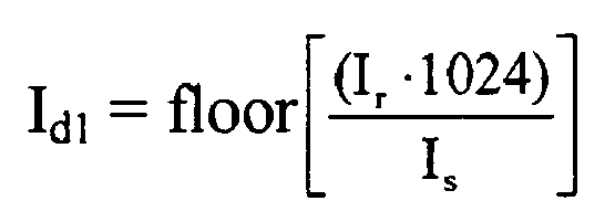
- Now, the same equations will be set forth using integer math. The Integer Values (di) in the table are integer representations of the Percent Deratings (dp). The Integer Values (di), stored in a memory accessible by
control circuit 26, are used bycontrol circuit 26 to represent the Percent Deratings (dp) to avoid the need for floating point math. Thus, the Integer Values (di) are generated as follows:
- The derated current rating is calculated as follows:

-
Control circuit 26 selects the Integer Value closest to the derated current rating (Id1). In this embodiment, Id1 is compared to each of the integer values until Id1 is greater than or equal to the integer value. Then, the integer value just after the greater than or equal to integer value is selected as di[J]. Again, this method is employed for ease of computation. Alternatively, the Integer Value just before the greater than or equal to Integer Value could be selected, or another method may be employed to obtain the Integer Value closest to the derating current rating (Id1). The Program Message corresponding to di[J] (i.e., Program_ Message[J]) is then provided toprogrammable amplifiers 30a-e. The corresponding Derating Gain Value represents the actual gain ofprogrammable amplifiers 30a-e applied to the sense signals. - Next, an error correction value is calculated as follows:


control circuit 26 to provide a more accurate representation of the sensed current, for example, as described hereinabove. - Using the integer math routine described above, where the data message indicates that the sensing circuits (Is) are rated at 600 Amps and the breaker (Ir) is rated at 550 Amps, Id1 is calculated as follows:

- Next an Integer Value closest to the derated current rating (Id1) is selected by comparing Id1 to each Integer Value until it is found that 938 exceeds 936 (i.e., J=12). In this example, the next midrange integer value 964 is selected as di[13]. With J=13, Program _Message[13], "0010", is provided to
programmable amplifiers 30a-e. - Next, the error correction value (e) is calculated as follows:


- In this example, the error e = 0.120 is marginal relative to errors introduced in the sampling and signal conditioning process. Therefore, the error correction value (e) is not applied to the sense signals.
- One particularly advantageous aspect of the present invention is that a new circuit breaker rating (e.g., 700 Amps) can be added to an existing product line without requiring new CTs, new electronic trip units, or new software. The control circuit is simply provided with the new circuit breaker rating and the rating of the current transformers being used (e.g., rated greater than or equal to 700 Amps), and the control circuit and ASIC condition the sense signals for the new rating.
- Referring now to
FIG. 3 , a method of constructing or manufacturing a circuit breaker is disclosed. Acircuit breaker component 56 is provided as a frame in this embodiment, but may alternatively be a casing, a sensing circuit, a trip mechanism, or other circuit breaker component. A computer-readable indicia 58 (e.g., a label having a bar code) is coupled to or applied tocomponent 56 to indicate the desired rating (e.g., 200 Amps) ofcircuit breaker component 56 which may be, for example, a rating corresponding to the rating of a sensing circuit associated with the circuit breaker.Indicia 58 also indicates the rating of the sensing circuits to be installed in the circuit breaker. - Next, one or more of
sensing circuits 60 are coupled tocircuit breaker component 56. In this step, acomputer 62 scans computer-readable indicia 58 to determine the rating of the sensing circuits to be installed. Based on the scanning step, sensing circuits of the desired rating (e.g., 200 Amps) are selected from abin 62 and coupled tocomponent 56. Alternatively,indicia 58 may include only a desired circuit breaker rating and not a desired sensing circuit rating in which case a sensing circuit rated at or above the rating of the circuit breakers are selected frombin 62 and coupled tocomponent 56. - Next, an electronic module 22 (e.g., an electronic trip unit) such as that disclosed hereinabove with respect to
FIGS. 1 and2 is coupled tocomponent 56.Electronic module 22 is selected from abin 64 containing a plurality of substantially similarelectronic modules 22. - Next,
control circuit 26 ofelectronic module 22 is programmed to tellelectronic module 22 the desired rating of the circuit breaker and the rating ofsensing circuits 60. Alternatively, the rating ofsensing circuits 60 can be scanned from an indicia affixed to one ofsensing circuits 60. - The final step illustrated in
FIG. 3 couples atrip mechanism 68 selected from atrip mechanism bin 70 tocomponent 56. A third computer 72scans indicia 58 and selects the proper trip mechanism, if necessary, frombin 70 for installation incomponent 56. - A further feature of
circuit breaker 10 relates to an improved method of repairingcircuit breaker 10. A maintenance person first diagnoses the malfunction of the circuit breaker, for example, by using the circuit breaker tester disclosed in commonly assigned U.S. Application No.09/435,187 electronic module 22, to the circuit breaker. Next, the maintenance person inputs the rating of the sensing circuits and the desired rating of the circuit breaker to a computer (e.g., a laptop, personal digital assistant, etc.), couples the computer to controlcircuit 26 ofelectronic module 22, and provides a data message to controlcircuit 26 to program the second electronic trip unit with the rating of the sensing circuits and the desired rating of the circuit breaker. Sinceelectronic module 22 includesprogrammable amplifier 30 andcontrol circuit 26, the maintenance person need only carry one general purpose electronic module rather than having to carry different electronic modules having different current ratings. Furthermore, since the present invention allows the use of one sensing circuit for multiple circuit breaker ratings, the maintenance person need carry fewer replacement sensing circuits than in the prior art. - While the embodiments illustrated in the FIGS. and described above are presently preferred, it should be understood that these embodiments are offered by way of example only. For example, while the programmable amplifier herein is part of an application specific integrated circuit, other configurations of programmable amplifiers are contemplated and other ways of programming the amplification of the sense signals are contemplated. The invention is not limited to a particular embodiment, but extends to various modifications that nevertheless fall within the scope of the appended claims.
Claims (17)
- A method of conditioning a sense signal generated by a sensing circuit (14,16,18,20) of a circuit breaker (10) having a circuit breaker rating Ir, the sensing circuit having a sensing circuit rating Is, comprising:receiving the sense signal from the sensing circuit of the circuit breaker (10);selecting one of a plurality of gain values stored in a memory based on at least one of the circuit breaker rating and the sensing circuit rating Is; andamplifying the sense signal based on the selected gain value, characterised by calculating an error correction value e based on the selected gain value and the sensing circuit rating Is where e = Ir - Id2 with I being the nominal breaker rating and Id2 = Is·dp[J] where dp[J] is a percent derating selected from memory closest to the circuit breaker rating Ir; and conditioning the sense signal based on the error correction value.
- The method of claim 1, wherein the plurality of gain values are integer values representative of derating gain values.
- The method of claim 1, wherein the gain value is selected based on the ratio of the circuit breaker rating to the sensing circuit rating.
- The method of claim 1, wherein the step of conditioning the sense signal includes conditioning the sense signal by the error correction value only if the error correction value exceeds a predetermined value.
- The method of claim 1, further comprising receiving a data message including the sensing circuit rating and the circuit breaker rating, wherein the circuit breaker rating is less than the sensing circuit rating.
- The method of claim 1, further comprising providing a data message to a programmable amplifier having a predetermined number of programmable gain values, wherein the programmable amplifier selects one of the programmable gain values based on the data message.
- The method of claim 6, wherein the predetermined number is approximately sixteen.
- The method of claim 1, wherein the plurality of gain values range between approximately 2.315 and 3.617.
- The method of claim 1, wherein the step of selecting includes selecting the one of the plurality of gain values corresponding to the derating percentage closest to the ratio of the circuit breaker rating to the sensing circuit rating.
- An apparatus for conditioning a sense signal generated by a sensing circuit (14,16,18,20) of a circuit breaker (10) having a circuit breaker rating Ir, the sensing circuit having a sensing circuit rating Is, comprising:means for receiving the sense signal from the sensing circuit;means (26) for selecting one of a plurality of gain values stored in a memory;means (30) for amplifying the sense signal based on the selected gain value;
characterised bymeans (26) for calculating an error correction value e based on the selected gain value and the sensing circuit rating IS where e = Ir - Id2 with Ir being the nominal breaker rating and Id2 = I·dp [J] where dp[J] is a percent derating selected from memory closest to the circuit breaker rating Ir; andmeans for conditioning the sense signal based on the error correction value e. - The apparatus of claim 10, wherein the means for amplifying the sense signal based on the error correction value includes amplifying the sense signal by the error correction value only if the error correction value exceeds a predetermined value.
- The apparatus of claim 10, further comprising means for receiving a data message including the sensing circuit rating and the circuit breaker rating, wherein the circuit breaker rating is less than the sensing circuit rating.
- The apparatus of claim 10, further comprising means for providing a data message to a programmable amplifier means having a predetermined number of programmable gain values, the programmable amplifier means for selecting one of the programmable gain values based on the data message.
- The apparatus of claim 13, wherein the predetermined number is approximately sixteen.
- The apparatus of claim 10, wherein the plurality of gain values range between approximately 2.315 and 3.617.
- The apparatus of claim 10, wherein the plurality of gain values correspond to derating percentages ranging between a first predetermined percentage and a second predetermined percentage.
- The apparatus of claim 16, wherein the means for selecting includes selecting the one of the plurality of gain values corresponding to the derating percentage closest to the ratio of the circuit breaker rating to the sensing circuit rating.
Applications Claiming Priority (2)
| Application Number | Priority Date | Filing Date | Title |
|---|---|---|---|
| US435109 | 1989-11-13 | ||
| US43510999A | 1999-11-05 | 1999-11-05 |
Publications (3)
| Publication Number | Publication Date |
|---|---|
| EP1098413A2 EP1098413A2 (en) | 2001-05-09 |
| EP1098413A3 EP1098413A3 (en) | 2002-07-10 |
| EP1098413B1 true EP1098413B1 (en) | 2010-11-24 |
Family
ID=23727024
Family Applications (1)
| Application Number | Title | Priority Date | Filing Date |
|---|---|---|---|
| EP20000203781 Expired - Lifetime EP1098413B1 (en) | 1999-11-05 | 2000-10-31 | Method and apparatus for conditioning a sense signal in a circuit breaker |
Country Status (3)
| Country | Link |
|---|---|
| EP (1) | EP1098413B1 (en) |
| DE (1) | DE60045272D1 (en) |
| ES (1) | ES2357396T3 (en) |
Families Citing this family (2)
| Publication number | Priority date | Publication date | Assignee | Title |
|---|---|---|---|---|
| US10320177B2 (en) * | 2012-12-13 | 2019-06-11 | Emneve Pty Limited | Power distribution system and method, and circuit breaker for use therein |
| CN104836222B (en) * | 2014-02-07 | 2019-07-05 | 通用电气公司 | With the method and apparatus of power management in ETU in breaker when host |
Family Cites Families (1)
| Publication number | Priority date | Publication date | Assignee | Title |
|---|---|---|---|---|
| US5525985A (en) | 1990-12-28 | 1996-06-11 | Eaton Corporation | Sure chip |
-
2000
- 2000-10-31 ES ES00203781T patent/ES2357396T3/en not_active Expired - Lifetime
- 2000-10-31 EP EP20000203781 patent/EP1098413B1/en not_active Expired - Lifetime
- 2000-10-31 DE DE60045272T patent/DE60045272D1/en not_active Expired - Lifetime
Also Published As
| Publication number | Publication date |
|---|---|
| DE60045272D1 (en) | 2011-01-05 |
| EP1098413A3 (en) | 2002-07-10 |
| EP1098413A2 (en) | 2001-05-09 |
| ES2357396T3 (en) | 2011-04-26 |
Similar Documents
| Publication | Publication Date | Title |
|---|---|---|
| EP1098412B1 (en) | Circuit breaker having programmable amplifier | |
| US5467012A (en) | Power monitoring | |
| EP0949733B1 (en) | Accessory network for an electronic trip unit | |
| JP3955706B2 (en) | Circuit breaker with energization information measuring device and correction method thereof | |
| US4788620A (en) | Static trip circuit breaker with automatic circuit trimming | |
| CA1242791A (en) | Circuit breaker static trip unit having automatic circuit trimming | |
| US5289191A (en) | Bipolar analog-to-digital conversion apparatus with unipolar current and voltage modes | |
| US8116054B2 (en) | Universal rating plug for electronic trip unit | |
| ZA200007591B (en) | Current detector and current measurement apparatus including such detector. | |
| US20020084914A1 (en) | Revenue meter arrangement having sensors in mounting device | |
| US7309993B2 (en) | Three- or four-pole low-voltage power switch with Rogowski coils operating as current sensors | |
| US4703389A (en) | Static trip circuit breaker with automatic circuit trimming | |
| WO2008147517A1 (en) | Device protection using temperature compensation | |
| EP1111752B1 (en) | Instantaneous fault detection circuit method and apparatus | |
| EP1383219B1 (en) | Distance relay apparatus | |
| US5479315A (en) | Protective relay for power systems capable of being tested with low-level voltage and current signals | |
| EP1098413A2 (en) | Method & apparatus for conditioning a sense signal in a circuit breaker | |
| US6621672B2 (en) | Circuit breaker having analog override | |
| KR100868892B1 (en) | Remote monitoring and data acquisition system of distribution system | |
| NZ280855A (en) | Power monitor with wide dynamic range: precision resistors switchable into amplifier feedback loop | |
| EP2110915A2 (en) | Current gain control of circuit breaker trip unit | |
| JPH03277115A (en) | Protective device | |
| US20060176060A1 (en) | Method and circuit arrangement for the detection of ground faults on electronic trips for low-voltage circuit breakers comprising serially connected measuring amplifiers | |
| KR20210051682A (en) | Controlling system of load bank and controlling method thereof | |
| JP4877088B2 (en) | Input circuit device for wide-area current transformer |
Legal Events
| Date | Code | Title | Description |
|---|---|---|---|
| PUAI | Public reference made under article 153(3) epc to a published international application that has entered the european phase |
Free format text: ORIGINAL CODE: 0009012 |
|
| AK | Designated contracting states |
Kind code of ref document: A2 Designated state(s): AT BE CH CY DE DK ES FI FR GB GR IE IT LI LU MC NL PT SE |
|
| AX | Request for extension of the european patent |
Free format text: AL;LT;LV;MK;RO;SI |
|
| PUAL | Search report despatched |
Free format text: ORIGINAL CODE: 0009013 |
|
| AK | Designated contracting states |
Kind code of ref document: A3 Designated state(s): AT BE CH CY DE DK ES FI FR GB GR IE IT LI LU MC NL PT SE |
|
| AX | Request for extension of the european patent |
Free format text: AL;LT;LV;MK;RO;SI |
|
| 17P | Request for examination filed |
Effective date: 20021230 |
|
| AKX | Designation fees paid |
Designated state(s): DE ES FR GB IT |
|
| 17Q | First examination report despatched |
Effective date: 20090813 |
|
| GRAP | Despatch of communication of intention to grant a patent |
Free format text: ORIGINAL CODE: EPIDOSNIGR1 |
|
| RTI1 | Title (correction) |
Free format text: METHOD AND APPARATUS FOR CONDITIONING A SENSE SIGNAL IN A CIRCUIT BREAKER |
|
| RAP1 | Party data changed (applicant data changed or rights of an application transferred) |
Owner name: SIEMENS INDUSTRY, INC. |
|
| GRAS | Grant fee paid |
Free format text: ORIGINAL CODE: EPIDOSNIGR3 |
|
| GRAA | (expected) grant |
Free format text: ORIGINAL CODE: 0009210 |
|
| AK | Designated contracting states |
Kind code of ref document: B1 Designated state(s): DE ES FR GB IT |
|
| REG | Reference to a national code |
Ref country code: GB Ref legal event code: FG4D |
|
| REF | Corresponds to: |
Ref document number: 60045272 Country of ref document: DE Date of ref document: 20110105 Kind code of ref document: P |
|
| REG | Reference to a national code |
Ref country code: ES Ref legal event code: FG2A Ref document number: 2357396 Country of ref document: ES Kind code of ref document: T3 Effective date: 20110426 |
|
| PLBE | No opposition filed within time limit |
Free format text: ORIGINAL CODE: 0009261 |
|
| STAA | Information on the status of an ep patent application or granted ep patent |
Free format text: STATUS: NO OPPOSITION FILED WITHIN TIME LIMIT |
|
| 26N | No opposition filed |
Effective date: 20110825 |
|
| REG | Reference to a national code |
Ref country code: DE Ref legal event code: R097 Ref document number: 60045272 Country of ref document: DE Effective date: 20110825 |
|
| GBPC | Gb: european patent ceased through non-payment of renewal fee |
Effective date: 20111031 |
|
| REG | Reference to a national code |
Ref country code: FR Ref legal event code: ST Effective date: 20120629 |
|
| PG25 | Lapsed in a contracting state [announced via postgrant information from national office to epo] |
Ref country code: DE Free format text: LAPSE BECAUSE OF NON-PAYMENT OF DUE FEES Effective date: 20120501 |
|
| REG | Reference to a national code |
Ref country code: DE Ref legal event code: R119 Ref document number: 60045272 Country of ref document: DE Effective date: 20120501 |
|
| PG25 | Lapsed in a contracting state [announced via postgrant information from national office to epo] |
Ref country code: IT Free format text: LAPSE BECAUSE OF NON-PAYMENT OF DUE FEES Effective date: 20111031 Ref country code: GB Free format text: LAPSE BECAUSE OF NON-PAYMENT OF DUE FEES Effective date: 20111031 Ref country code: FR Free format text: LAPSE BECAUSE OF NON-PAYMENT OF DUE FEES Effective date: 20111102 |
|
| REG | Reference to a national code |
Ref country code: ES Ref legal event code: FD2A Effective date: 20130826 |
|
| PG25 | Lapsed in a contracting state [announced via postgrant information from national office to epo] |
Ref country code: ES Free format text: LAPSE BECAUSE OF NON-PAYMENT OF DUE FEES Effective date: 20111101 |