EP1098396A2 - High durability, low mating force electrical connectors - Google Patents
High durability, low mating force electrical connectors Download PDFInfo
- Publication number
- EP1098396A2 EP1098396A2 EP00309747A EP00309747A EP1098396A2 EP 1098396 A2 EP1098396 A2 EP 1098396A2 EP 00309747 A EP00309747 A EP 00309747A EP 00309747 A EP00309747 A EP 00309747A EP 1098396 A2 EP1098396 A2 EP 1098396A2
- Authority
- EP
- European Patent Office
- Prior art keywords
- electrical connector
- housing
- camming
- molded
- mating
- Prior art date
- Legal status (The legal status is an assumption and is not a legal conclusion. Google has not performed a legal analysis and makes no representation as to the accuracy of the status listed.)
- Withdrawn
Links
Images



Classifications
-
- H—ELECTRICITY
- H01—ELECTRIC ELEMENTS
- H01R—ELECTRICALLY-CONDUCTIVE CONNECTIONS; STRUCTURAL ASSOCIATIONS OF A PLURALITY OF MUTUALLY-INSULATED ELECTRICAL CONNECTING ELEMENTS; COUPLING DEVICES; CURRENT COLLECTORS
- H01R13/00—Details of coupling devices of the kinds covered by groups H01R12/70 or H01R24/00 - H01R33/00
- H01R13/62—Means for facilitating engagement or disengagement of coupling parts or for holding them in engagement
- H01R13/627—Snap or like fastening
- H01R13/6271—Latching means integral with the housing
- H01R13/6273—Latching means integral with the housing comprising two latching arms
-
- H—ELECTRICITY
- H01—ELECTRIC ELEMENTS
- H01R—ELECTRICALLY-CONDUCTIVE CONNECTIONS; STRUCTURAL ASSOCIATIONS OF A PLURALITY OF MUTUALLY-INSULATED ELECTRICAL CONNECTING ELEMENTS; COUPLING DEVICES; CURRENT COLLECTORS
- H01R13/00—Details of coupling devices of the kinds covered by groups H01R12/70 or H01R24/00 - H01R33/00
- H01R13/62—Means for facilitating engagement or disengagement of coupling parts or for holding them in engagement
- H01R13/629—Additional means for facilitating engagement or disengagement of coupling parts, e.g. aligning or guiding means, levers, gas pressure electrical locking indicators, manufacturing tolerances
- H01R13/631—Additional means for facilitating engagement or disengagement of coupling parts, e.g. aligning or guiding means, levers, gas pressure electrical locking indicators, manufacturing tolerances for engagement only
- H01R13/6315—Additional means for facilitating engagement or disengagement of coupling parts, e.g. aligning or guiding means, levers, gas pressure electrical locking indicators, manufacturing tolerances for engagement only allowing relative movement between coupling parts, e.g. floating connection
Definitions
- This invention is related to matable electrical connectors in which spring beam terminals in one of the connectors are deflected prior to mating engagement with terminals in the other connector to reduce the mating force and to enhance the durability of the terminals and of the plating on the terminals.
- Zero insertion force (ZIF) or low insertion force (LIF) electrical connectors or sockets typically employ some form of cam member to reduce or eliminate the insertion force as two electrical connectors are mated. These connectors are typically used to reduce or eliminate the frictional force between mating male and female terminals. This frictional or mating force can result in damage to the terminals and to the electroplating used to ensure an good electrically conductive interface. High mating forces can also reduce the number of mating and unmating cycles for which specific terminals can be employed. Terminals and connectors that have distinct advantages for certain applications cannot be used for potentially related applications in which the connectors must be mated or unmated more frequently because of damage to the mating interface.
- US Patent 4,350,402 discloses one such board mounted zero insertion force electrical connector in which female terminals are located in an inner housing and an outer housing includes inclined actuating surfaces for spreading the contact beams when the outer housing is shifted relative to the terminals and to the inner housing. A linear cam is used to impart movement between the two housings resulting in separation of opposed contact arms.
- US Patent 4,067,633 also employs two shiftable housings and inclined contact actuating surfaces on the housing that moves toward the mating ends of the spring contacts. This latter connector employs external handles on the connector attached to wires.
- US Patent 4,655,526 discloses another low insertion force electrical connector in which spring beams are initially held in a partially open position and are then released when two connectors are mated.
- this approach requires a complicated contact structure including insertion of a coil spring between spring beams. This contact structure differs significantly from standard contacts that have proved reliable in may applicatons.
- the instant invention overcomes many of these disadvantages by providing an electrical connector in which mating force is significantly reduced in a configuration in which the connectors are mated by simply inserting one connector into another without manipulation of a separate cam actuator.
- This invention permits standard female or receptacle terminals, that are typically intended to be used for a limited number of mating and unmating cycles to be employed in applications requiring many more mating cycles.
- One of the objects of this invention is to permit standard receptacle terminals that are commonly used in automotive applications as input and output terminals for attaching other components or appliances to the a vehicle electrical system. For example, this approach will allow portable electronic devices to be repeatably connected and disconnected to an electronic bus in the vehicle.
- Another object achieved by invention is to provide this capability without significant cost disadvantages and without requiring numerous additional components while still being relatively easily molded.
- One especially significant advantage of this invention is that the two connectors cannot be mated or unmated without first deflecting spring beam terminals so that male terminals can be inserted or removed without damage to the contact interface and to the plating on the terminals.
- This electrical connector assembly also incorporates by a cam actuation function and a connector latching function. Disengagement of the connector latch also separates the terminal mating interface so that the connectors can be unmated without damage to the terminals.
- the first electrical connector includes first and second housings and female terminals.
- the first housing includes cavities with the female terminals secured in the cavities and a deflectable camming lever.
- the second housing includes camming surfaces engageable with the female terminals to open the female terminals.
- the second electrical connector includes a mating housing and male terminals insertable into mating engagement with the female terminals.
- the mating housing includes a surface engagable with the camming lever during mating to deflect the camming lever and shift the second housing relative to the first housing and open the female terminals for insertion of the male terminals.
- the first electrical connector has a molded housing with a molded latch engagable with the second electrical connector to latch the connectors in a mating position.
- the molded latch includes a camming surface for shifting a portion of the first electrical connector relative to the molded housing as the first and second electrical connectors are mated.
- the first electrical connector of this assembly has a front mating face and a rear face.
- the terminals in this first connector have a deflectable spring contact section.
- a rear housing in this first connector includes cavities in which the terminals are secured.
- a front housing telescopes relative to the rear housing between a first forward and a second relative rearward position.
- the front housing has a front panel with a plurality of openings and camming projections on an interior surface of the front panel located adjacent the openings and facing rearward.
- a camming member is located adjacent to the front mating face of the connector.
- the second electrical connector includes a housing abutting the camming member when mated with the first electrical connector to deflect the camming member to cause deflection of the spring contact sections.
- the electrical connector assembly 2 shown in Figure 1, includes a first electrical connector 10 mated to a second electrical connector 60.
- the first electrical connector 10 is a receptacle connector and includes a number of female contacts or terminals 50, shown in Figure 7.
- the second electrical connector 60 is a plug connector that includes a plurality of pins 80 of conventional type, such as those shown in Figure 11, or other conventional male terminals or leads.
- the first connector 60 includes a shiftable cam 40 in the form of a front housing member that deflects or spreads the spring beam contact section 52 on female terminals 50 as the pins are inserted between the spring beam contact sections 52.
- the spring beam contact sections 52 are released to engage the pins 80 to establish an electrical connection between mating terminals.
- the shiftable front housing cam 40 can also be moved into engagement with the spring beam contact sections 52 to disengage the spring beam contacts 50 from the pins 80 when the connectors 10 and 60 are to be unmated. This camming action permits many more mating and unmating cycles than would typically possible for the contact in question and for the plating on the mating sections of these terminals.
- the receptacle connector 10 includes a two part housing with female or receptacle terminals 50 mounted in the connector 10.
- the rear housing 20, shown in Figure 3 includes terminal cavities 22 extending forward from the rear face or end 14 of this first electrical connector 10. In the representative embodiment, there are two parallel rows of cavities 22.
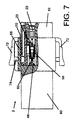
- Molded terminal latches 23 extend from the molded housing 10 into each of the terminal cavities 22 secure the female terminals 50, as shown in Figure 7. These deflectable molded latches 23 permit insertion of the terminals 30 through the rear end 14, and engage the terminals 50 to prevent retraction of the terminals.
- These molded latches 23 are conventional and are used in many electrical connectors, especially those used in automotive applications.
- FIG. 7 shows that the mating or contact section 52 extends beyond the rear housing 20 and beyond a front end of the terminal cavities 22 in housing 20.
- the spring beam contacts forming the contact section 52 are exposed on the front of the housing 20. As will be subsequently discussed, these spring beam contact 52 are positioned to enter openings in the front housing 40 so that the spring beam contacts 52 can be outwardly deflected for receiving mating pins or male terminals 80.
- the preferred embodiment of the rear housing 20 is molded as one piece.
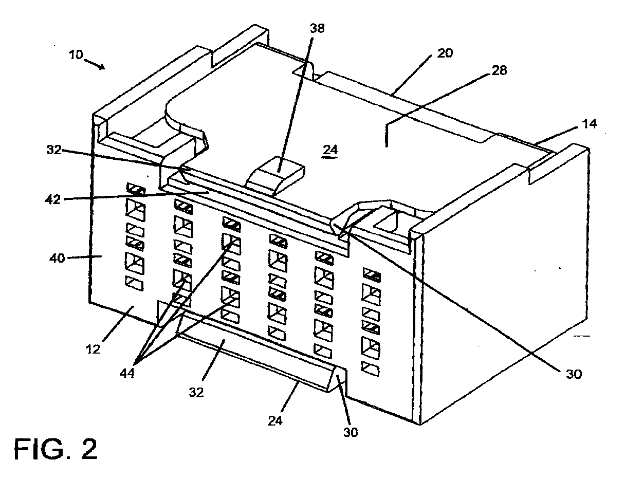
- Each camming member 24 is molded as a cantilever beam with the cantilever beam base 36 joined to the main body of the rear housing 20 adjacent the rear face 14 of the receptacle connector 10.
- Each cantilever beam camming member 24 extends toward the front or mating housing end 12.
- a camming protrusion 30 extends from the inner surface 26 adjacent the free or distal end of the cantilever camming member 24.
- This camming protrusion 30 faces inward and is located beyond the forward most part of the body of the rear housing 20.
- Camming protrusions 30 on the two camming members 24 extend from the top and bottom sides of the rear housing 20 as viewed in Figure 3.
- Each camming protrusion 30 has an inclined leading edge or face 32 and an inclined trailing edge or face 34 so that the camming protrusions 30 have a generally triangular cross section.
- These inclined faces 32 and 34 are sloped so that a surface engaging either face during mating and unmating or the two connectors 10, 60, or during assembly of the two connector housings 20, 40, will slide along the sloping surface and outwardly deflect the two camming members 24.
- Each of the camming members 24 also includes a latching protrusion 38 extending from the outer surface 28 adjacent to its distal, forward or free end.
- One latching protrusion 38 is located near the center of each of the camming members 24 and the width of the latching protrusions 38 is less than the width of the camming protrusions 30 on the same camming member 24.
- the latching protrusions 38 have a curved forward end 37 and an abruptly sloping rear end 39.
- the curved forward end 41 is configured to engage a surface on the mating connector 60 during mating to deflect the camming member 24 and the camming protrusion 30 inward.
- the shape rear edge 42 is intended to form a latching surface to hold the two connectors 10, 60 securely mated.
- Each camming member 24 thus serves both as a connector latching member and to cam the spring beam contact sections 52 in a manner that will be discussed in greater detail.
- Camming member 24 can therefore also be referred to as a camming lever 24, a camming latch 24, or a molded latch 24.
- the structure of the camming member 24 can also be termed a cantilever beam 24 or a camming arm 24.
- the front housing 40 is secured to the rear housing 20 by the camming latches 24.
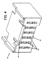
- Front housing 40 is shown in greater detail in Figures 4 and 5.
- the front housing which is also a one piece molded member, is assembled to the rear housing 20 after the female terminals 50 have been inserted into appropriate terminal cavities 22 from the rear of the rear housing 20.
- the front housing 40 has four sidewalls all joined along a forward edge to a front wall or panel 48.
- Rear housing 20 is inserted into the front housing 40 through the open rear of housing 40 with the four sidewalls enveloping the front portion of the rear housing 20.
- the top and bottom sidewalls of the front housing can be inserted between the camming arms 24 and the top and bottom of the rear housing 20.
- the trailing edge 34 of the adjacent camming protrusion 30 will engage a front edge 42 of the front housing 40 along the top and bottom of the front panel 48.
- the camming protrusions 30 will thus hold the front housing 40 on the rear housing 20. It is important to note, however, that telescoping movement of the front housing 40 relative to the rear housing 20 is still possible.
- the front housing 40 can move from its forward position shown in Figure 2, rearward relative to the rear housing 20 and to the female terminals 50, which are prevented from rearward movement relative to the rear housing 20 by the molded terminal latches 23.
- Figure 5 shows the interior or rear side of the front housing 40.
- the four sidewalls and the front wall or panel 48 form a cavity in which the front portion of the rear housing 20 is received.
- a series of camming openings 44 are formed in the front panel 48.
- Each of these openings 44 is aligned with a terminal cavity 22 in the rear housing 20, and each opening is configured so that the front of the mating terminal section 52 fits within an aligned opening 44.
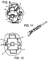
- An enlarged view of one of these terminal openings 44 is shown in Figure 9.
- Figure 10 is a rear view of one of these openings 44 in which the outer edges of an opening 44 are show.
- the interior surfaces which appear in Figure 9 appear as lines in this view.
- Each terminal opening 44 is larger at its rear than at its front.
- a small opening 43 extends completely through the front panel 48 so that a pin 80 in the mating connector 60 can pass through the front housing 40 to mate with a corresponding female terminal 50.
- Sloping camming projections 46 surround the opening 43. These camming projections slope rearwardly toward an apex located generally along the horizontal centerline of both the opening 44 and the smaller pin opening 43 in the manner best seen in Figure 7.
- Each camming projection 46 has a sloping top surface 45 and a sloping lower surface 47 as seen in Figure 9.
- Each camming projection 46 is configured to fit between the upper and lower spring beams of the receptacle terminal mating section 52 of one receptacle terminal 50.
- Each opening 44 is dimensioned so that the front mating portion 52 will fit within the rear portion of the opening 44.
- the camming projections 46 will engage the spring beams of the terminal 50 forcing them apart so that a male terminal or pin 80 can be inserted between the spring beams either with no mating force generated by the engagement of the male and female terminals or with a reduced mating force.
- This reduction in mating force will not only prevent damage to the physical structure of the terminals, but will also prevent damage to the electroplating added to the terminals to improve the mating interface.
- Reduction in mating force will also permit the terminals to be mated and unmated for significantly more cycles than would be possible for an otherwise comparable full force mating configuration.
- Adequate space at the top and bottom of each opening 44 is provided to permit the spring beams to flex outward.
- openings may be provided above and below the pin openings 43 so that the terminals can be probed from the front to check for continuity. These probe openings provide access to the terminal 50 when the connector 10 is mounted in a panel or bulkhead and would otherwise be inaccessible.
- the front housing 40 can also be referred to as a cam or cam insert or cam actuator since movement of the front housing 40 toward the rear housing 20 cams the terminal mating sections 52 outward. Rearward movement of the front housing 40 relative to the rear housing 20 is imparted by inward deflection of the camming members 24 and the camming protrusions 30. When the camming members 24 is inwardly deflected, the camming protrusions 30 engage the front edge 42 of front housing 40 causing it to move rearwardly from the front position shown in Figures 2 and 7. When the plug connector 60 is mated to the receptacle connector 10, the camming protrusions 30 will result when the plug connector housing 62 engages the camming members 24.
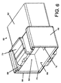
- the male or plug connector housing 62 is shown in Figure 6. Together with the male terminals or pins 80, this housing 62 forms the plug or male connector 60.
- Plug connector housing 62 is molded, normally from the same material as the two housings 20 and 40, which are part of the receptacle connector 10.
- a plug housing cavity 64 is formed on the mating side of the plug housing 62 by a shroud formed for four walls, two sidewalls 66 and top and bottom walls 68.
- Male terminals or pins 80 extend into the cavity 64, which is shaped so that the mating end 12 of connector 10 will fit within the cavity 64.
- each wall 68 When the two connectors are mated the top and bottom walls 68 function as engaging surfaces which abut the outer latching protrusions 38 on the camming members 24 to cause the inner camming protrusions 30 to engage and shift the front housing 40 rearwardly toward the rear housing 20 and into engagement with the female spring beam terminals 50.
- the front edge of each wall 68 has a beveled surface 70, which initially engages the latching protrusion 38 so that the connectors can be smoothly mated.
- Each housing wall 68 includes an opening 76 that is at least as large as the latching protrusion 38.
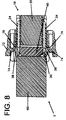
- One of these openings 76 is partially shown in Figure 6, and Figure 8 shows both latching protrusions 38 received within a latching opening 76.
- Latching edge 39 engages a latching edge 78 in the wall opening 76 of the plug connector 60.
- the latching opening 76 on the top wall 68 is obscured in Figure 6 by the top depressible release member or appendage 72.
- Openings 76 are recessed from the leading edge of walls 68 and from the beveled surface 70 along this leading edge.
- the spring beams themselves provide the spring force necessary to cause the front housing 40 to its forward on extended position. In this extended position the camming projections 46 do not exert any significant force on the terminal spring beams and do not interfere with the mating engagement between female terminals 50 and male terminals 80.
- an auxiliary spring or springs can be added to push the front cam 40 back to its extended position, In still other embodiments sufficient spring force may be provided by relying on only a portion of the resilient contacts to return the front cam to its extended position. In this context, it should also be understood that in some applications only a portion of the terminals need be cammed open in the manner discussed herein.
- the male connector 60 provides means for zero or reduced force unmating as well as for mating.
- the housing 62 includes a depressible or deflectable release member 72 on the exterior of the top and bottom walls 68. These release members 72 are molded as part of the housing 62. Each release member 72 includes a release probe 74 in the form of a finger extending inwardly from the inner surface of the depressible member 72. These release probes or fingers 74 are located immediately above the openings 76 in the walls 68. When the release members 72 are depressed, the release probes 74 engage the latching protrusions 38 and force or cam the camming levers 24 to their inner or activated position.
- the camming protrusions 30 again engage the front edge 42 of the front housing or cam actuator 40 resulting in deflection of the spring beam contact sections 52 away from pins 80.
- the pins 80 can then be removed from the female contacts 50 without damage to either mating contact surface or terminal.
- This configuration also allows the terminals to be mated in a conventional manner without the necessity of rotating or shifting a separate cam lever.
- the cam housing 40 is shifted as the plug connector is mated to the receptacle connector in a conventional manner.
- the connectors can also be mated by movement of only one connector while the other connector remains stationary.
- the receptacle connector can be mounted in a panel or bulkhead opening and secured by screws or by conventional panel mount flanges located on the rear of the rear housing 20.
- the plug connector 40 can be mounted on the rear of a component to be assembled or on the end of a cable or cord.
- the male connector can be mounted in a stationary position and the female connector can be moved to mate with the stationary male connector.
- the two connectors can also be used to connect two wire harness, in which case both connectors would be free to move during mating.
- one of the connectors can be mounted to a printed circuit board, with pcb pins extending up through the housing.
- This cam approach can also be used for sockets or connectors for mounting integrated circuit components or for ZIF pin grid array packages. For all of these applications a zero insertion force, low insertion force or reduced insertion force connection can be accomplished without the necessity of manipulating a separate cam actuator or lever.
- the spring biased contacts are deflected or spread apart simply as a result of inserting one connector into engagement with the other with movement being necessary only in one direction or along one mating axis.
Landscapes
- Details Of Connecting Devices For Male And Female Coupling (AREA)
- Connector Housings Or Holding Contact Members (AREA)
Abstract
Description
Claims (17)
- An electrical connector assembly comprising matable first and second electrical connectors, the first electrical connector including a molded housing with a molded latch engagable with the second electrical connector to latch the connectors in a mating position, characterized in that the molded latch also includes a camming surface for shifting a portion of the first electrical connector relative to the molded housing as the first and second electrical connectors are mated.
- The electrical connector assembly of claim 1 further characterized in that the camming surface is located on an inner surface of the molded latch.
- The electrical connector assembly of claim 2 further characterized in that the camming surface engages a shiftable member including camming projections engagable with at least one terminal in the first connector molded housing.
- The electrical connector assembly of claim 3 further characterized in that the shiftable members comprises a second molded housing section mounted on the molded housing including the molded latch.
- The electrical connector assembly of claim 4 further characterized in that the molded latch secures the second molded housing section to the molded housing including the molded latch.
- The electrical connector assembly of claim 5 further characterized in that the camming surface on the molded latch engages a front edge of the second molded housing section.
- The electrical connector assembly of claim 4 further characterized in that the molded latch extends from adjacent a rear end of the molded housing including the molded latch and the second molded housing section is located on a mating end spaced from the rear end.
- The electrical connector assembly of claim 7 further characterized in that the second molded housing section surrounds a portion of the molded housing including the molded latch.
- The electrical connector assembly of claim 7 further characterized in that the molded latch is located on the exterior of the second molded housing section.
- An electrical connector having a front mating face and a rear face, the electrical connector comprising:terminals having a deflectable spring contact section;a rear housing including cavities in which the terminals are secured, characterized in that:
a telescoping front housing is provided which is movable relative to the rear housing between a first forward and a second relative rearward position, the front housing has a front panel with a plurality of openings and camming projections on an interior surface of the front panel located adjacent the openings and facing rearward and a camming member is located adjacent to the front mating face of the connector, wherein deflection of the camming member brings the camming member into engagement with the front housing and moves the front housing toward the second relative rearward position and toward the contacts to bring the camming projections into engagement with the spring contact sections to deflect the spring contact sections. - The electrical connector of claim 10 further characterized in that the camming member is secured to the rear housing.
- The electrical connector of claim 10 further characterized in that the camming member comprises an arm molded as part of the rear housing and joined to the housing adjacent to the rear face of the connector.
- The electrical connector of claim 12 further characterized in that the camming member comprises a cantilever beam engagable with the front housing on a front free end of the cantilever beam.
- The electrical connector of claim 13 further characterized in that the camming member includes an inner projection and an outer projection on the front end of the cantilever beam, the inner projection engaging the front housing when deflected and the outer projection being positioned to engage a mating connector so that the camming member is deflected when the electrical connector is mated to the mating connector.
- An electrical connector comprising a molded housing including a plurality of terminals, each terminal including a spring beam contact for mating with a mating terminal in a mating electrical member, characterized in that the electrical connector includes an actuator engagable with a spring beam contact to deflect the spring beam contact, the electrical connector further includes a camming lever engagable with the actuator to shift the actuator so that the spring beam contact is deflected, the camming lever being engagable with the mating member so that the camming lever is deflected to shift the actuator and deflect the spring beam contact as the mating electrical member is mated to the electrical connector.
- The electrical connector of claim 15 further characterized in that the camming lever is deflected toward the spring beam contact to shift the actuator into engagement with the spring beam contact to deflect the spring beam contact.
- The electrical connector of claim 15 further characterized in that the electrical connector is insertable into a cavity in the mating member, the mating member comprising a mating electrical connector.
Applications Claiming Priority (2)
| Application Number | Priority Date | Filing Date | Title |
|---|---|---|---|
| US16320199P | 1999-11-03 | 1999-11-03 | |
| US163201P | 1999-11-03 |
Publications (2)
| Publication Number | Publication Date |
|---|---|
| EP1098396A2 true EP1098396A2 (en) | 2001-05-09 |
| EP1098396A3 EP1098396A3 (en) | 2001-10-31 |
Family
ID=22588909
Family Applications (1)
| Application Number | Title | Priority Date | Filing Date |
|---|---|---|---|
| EP00309747A Withdrawn EP1098396A3 (en) | 1999-11-03 | 2000-11-03 | High durability, low mating force electrical connectors |
Country Status (2)
| Country | Link |
|---|---|
| US (1) | US6422887B1 (en) |
| EP (1) | EP1098396A3 (en) |
Cited By (1)
| Publication number | Priority date | Publication date | Assignee | Title |
|---|---|---|---|---|
| EP3096413A1 (en) * | 2011-11-23 | 2016-11-23 | 3M Innovative Properties Company | Latching connector assembly |
Families Citing this family (6)
| Publication number | Priority date | Publication date | Assignee | Title |
|---|---|---|---|---|
| JP4028316B2 (en) * | 2002-07-30 | 2007-12-26 | 矢崎総業株式会社 | connector |
| US7133572B2 (en) * | 2002-10-02 | 2006-11-07 | Siemens Corporate Research, Inc. | Fast two dimensional object localization based on oriented edges |
| US20040247252A1 (en) * | 2003-02-28 | 2004-12-09 | John Ehrenreich | Retractable fiber optic connector housing |
| DE102011005858A1 (en) * | 2011-03-21 | 2012-09-27 | Robert Bosch Gmbh | Direct plug-in element, in particular for vehicle control devices |
| US10211438B2 (en) * | 2014-07-01 | 2019-02-19 | Yazaki Corporation | Electronic component protecting cover |
| US9583845B1 (en) | 2015-10-27 | 2017-02-28 | Dell Products, Lp | Electrical connector for an information handling system |
Family Cites Families (16)
| Publication number | Priority date | Publication date | Assignee | Title |
|---|---|---|---|---|
| US4047791A (en) | 1974-12-06 | 1977-09-13 | Amp Incorporated | Low insertion force receptacle and cammed housing |
| FR2356290A1 (en) * | 1976-06-24 | 1978-01-20 | Souriau & Cie | Connector with large number of contacts - has clamping device pressing on plug when it is fully inserted |
| DE2711032C2 (en) | 1976-03-17 | 1982-04-29 | Souriau et Cie. S.A., 92103 Boulogne-Billancourt, Seine | Electrical connector |
| US4067633A (en) | 1976-12-20 | 1978-01-10 | Amp Incorporated | Cam actuated low insertion force connector |
| US4350402A (en) | 1980-09-17 | 1982-09-21 | Amp Incorporated | Board mount zero insertion force connector |
| US4491377A (en) | 1982-04-19 | 1985-01-01 | Pfaff Wayne | Mounting housing for leadless chip carrier |
| US4684194A (en) | 1984-07-16 | 1987-08-04 | Trw Inc. | Zero insertion force connector |
| US4655526A (en) | 1984-08-31 | 1987-04-07 | Amp Incorporated | Limited insertion force contact terminals and connectors |
| US4618199A (en) | 1985-08-30 | 1986-10-21 | Pfaff Wayne | Low insertion force socket |
| US4685886A (en) | 1986-06-27 | 1987-08-11 | Amp Incorporated | Electrical plug header |
| US4787866A (en) | 1988-04-14 | 1988-11-29 | Amp Incorporated | Connector for unlocking conductive members from conductive pins |
| US4984993A (en) | 1989-05-12 | 1991-01-15 | Cray Research, Inc. | Two-piece edge ZIF connector with sliding block |
| US5061197A (en) | 1989-05-19 | 1991-10-29 | Yazaki Corporation | Multi-terminal electric connector requiring low insertion and removal force |
| US4978315A (en) | 1990-04-10 | 1990-12-18 | Molex Incorporated | Multiple-conductor electrical connector and stamped and formed contacts for use therewith |
| JPH089913Y2 (en) | 1992-02-03 | 1996-03-21 | 日本航空電子工業株式会社 | connector |
| US5254012A (en) | 1992-08-21 | 1993-10-19 | Industrial Technology Research Institute | Zero insertion force socket |
-
2000
- 2000-11-02 US US09/704,332 patent/US6422887B1/en not_active Expired - Fee Related
- 2000-11-03 EP EP00309747A patent/EP1098396A3/en not_active Withdrawn
Cited By (1)
| Publication number | Priority date | Publication date | Assignee | Title |
|---|---|---|---|---|
| EP3096413A1 (en) * | 2011-11-23 | 2016-11-23 | 3M Innovative Properties Company | Latching connector assembly |
Also Published As
| Publication number | Publication date |
|---|---|
| US6422887B1 (en) | 2002-07-23 |
| EP1098396A3 (en) | 2001-10-31 |
Similar Documents
| Publication | Publication Date | Title |
|---|---|---|
| JP2622938B2 (en) | Electrical connector with terminal position assurance member | |
| US5820399A (en) | Connector fitting construction | |
| US7637767B2 (en) | Cable connector assembly | |
| US7553188B2 (en) | Slide lock panel-mount connector | |
| US6736655B2 (en) | Rack and pinion electrical connector with offset gear teeth | |
| US5993255A (en) | Electrical connector with combination terminal guide and terminal position assurance member | |
| JP3285307B2 (en) | Half mating prevention connector | |
| US5273453A (en) | Electrical connector with positive latch | |
| CN101867123B (en) | Latch assembly for a pluggable electronic module | |
| US6027364A (en) | Connector fitting construction with side ribs and corresponding side rib-receiving portions | |
| EP0519264B1 (en) | Electrical connector | |
| US11670893B2 (en) | Socket connector for a connector system | |
| US5928027A (en) | Electrical connector system for a flat flexible circuit | |
| US12149027B2 (en) | High frequency connector with kick-out | |
| US6238227B1 (en) | Electrical connector for flexible flat cable | |
| EP1548894B1 (en) | A connector | |
| KR100198409B1 (en) | Self locking coupling terminal structure | |
| US6422887B1 (en) | High durability, low mating force electrical connectors | |
| JP2024055987A (en) | connector | |
| US12562527B2 (en) | Socket connector for a connector system having a latch for latching to a pin coupled to the socket connector | |
| US5928014A (en) | Electrical connector having a pair of connector housings | |
| JPH09289059A (en) | Connector | |
| CN115588887A (en) | Terminal system for connector systems | |
| US20250233361A1 (en) | Electrical connector having a mated verficiation switch | |
| US20250118914A1 (en) | Connector Assembly and Socket Connector |
Legal Events
| Date | Code | Title | Description |
|---|---|---|---|
| PUAI | Public reference made under article 153(3) epc to a published international application that has entered the european phase |
Free format text: ORIGINAL CODE: 0009012 |
|
| AK | Designated contracting states |
Kind code of ref document: A2 Designated state(s): AT BE CH CY DE DK ES FI FR GB GR IE IT LI LU MC NL PT SE TR Kind code of ref document: A2 Designated state(s): DE ES FR GB IT |
|
| AX | Request for extension of the european patent |
Free format text: AL;LT;LV;MK;RO;SI |
|
| PUAL | Search report despatched |
Free format text: ORIGINAL CODE: 0009013 |
|
| AK | Designated contracting states |
Kind code of ref document: A3 Designated state(s): AT BE CH CY DE DK ES FI FR GB GR IE IT LI LU MC NL PT SE TR |
|
| AX | Request for extension of the european patent |
Free format text: AL;LT;LV;MK;RO;SI |
|
| 17P | Request for examination filed |
Effective date: 20020429 |
|
| AKX | Designation fees paid |
Free format text: DE ES FR GB IT |
|
| 17Q | First examination report despatched |
Effective date: 20061031 |
|
| GRAP | Despatch of communication of intention to grant a patent |
Free format text: ORIGINAL CODE: EPIDOSNIGR1 |
|
| STAA | Information on the status of an ep patent application or granted ep patent |
Free format text: STATUS: THE APPLICATION IS DEEMED TO BE WITHDRAWN |
|
| 18D | Application deemed to be withdrawn |
Effective date: 20071117 |