EP1098323A2 - Optical disc camcorder - Google Patents
Optical disc camcorder Download PDFInfo
- Publication number
- EP1098323A2 EP1098323A2 EP00402689A EP00402689A EP1098323A2 EP 1098323 A2 EP1098323 A2 EP 1098323A2 EP 00402689 A EP00402689 A EP 00402689A EP 00402689 A EP00402689 A EP 00402689A EP 1098323 A2 EP1098323 A2 EP 1098323A2
- Authority
- EP
- European Patent Office
- Prior art keywords
- optical disc
- base plate
- plate assembly
- camcorder
- main body
- Prior art date
- Legal status (The legal status is an assumption and is not a legal conclusion. Google has not performed a legal analysis and makes no representation as to the accuracy of the status listed.)
- Granted
Links
Images











Classifications
-
- H—ELECTRICITY
- H04—ELECTRIC COMMUNICATION TECHNIQUE
- H04N—PICTORIAL COMMUNICATION, e.g. TELEVISION
- H04N5/00—Details of television systems
- H04N5/76—Television signal recording
- H04N5/84—Television signal recording using optical recording
- H04N5/85—Television signal recording using optical recording on discs or drums
-
- G—PHYSICS
- G11—INFORMATION STORAGE
- G11B—INFORMATION STORAGE BASED ON RELATIVE MOVEMENT BETWEEN RECORD CARRIER AND TRANSDUCER
- G11B31/00—Arrangements for the associated working of recording or reproducing apparatus with related apparatus
- G11B31/006—Arrangements for the associated working of recording or reproducing apparatus with related apparatus with video camera or receiver
-
- H—ELECTRICITY
- H04—ELECTRIC COMMUNICATION TECHNIQUE
- H04N—PICTORIAL COMMUNICATION, e.g. TELEVISION
- H04N5/00—Details of television systems
- H04N5/76—Television signal recording
- H04N5/765—Interface circuits between an apparatus for recording and another apparatus
- H04N5/77—Interface circuits between an apparatus for recording and another apparatus between a recording apparatus and a television camera
- H04N5/772—Interface circuits between an apparatus for recording and another apparatus between a recording apparatus and a television camera the recording apparatus and the television camera being placed in the same enclosure
-
- G—PHYSICS
- G11—INFORMATION STORAGE
- G11B—INFORMATION STORAGE BASED ON RELATIVE MOVEMENT BETWEEN RECORD CARRIER AND TRANSDUCER
- G11B2220/00—Record carriers by type
- G11B2220/20—Disc-shaped record carriers
- G11B2220/25—Disc-shaped record carriers characterised in that the disc is based on a specific recording technology
- G11B2220/2537—Optical discs
Definitions
- the present invention relates to an optical disc camcorder, in particular, the invention relates to means for correcting a skew which is caused between an optical disc and an optical pickup unit by effect of rolling generated in the camcorder.
- an optical disc camcorder integrally comprising a camera unit and a recorder unit using an optical disc as its recording medium converts video and audio data received by the camera unit into AV data signals for recording them onto the optical disc and then records the converted digital signal onto an optical-disc track via an optical pickup system.
- the optical pickup system executes recording of data signal by varying composition of the recording surface of the optical disc by way of condensing laser beams emitted from a semiconductor laser making up the light-emitting source onto an objective track position on the optical disc as of a minimal spot form via intermediate optical components and a laser-emitting object lens. Further, the optical pickup system executes reproduction of data signal by way of reading reflective light from the optical disc as an electrical signal via photoelectric conversion element such as a photo-detector or the like.
- the object lens of the optical pickup system for emitting laser beam is subject to focus control performed against optical disc recording surface set to a biaxial actuator and also subject to tracking control in order that a condensed light spot can precisely follow up the track on the optical disc.
- Perpendicularity between an optical axis of the object lens and the recording surface of the optical disc is one of extremely important factors to determine signal recording and reproduction characteristics. Deflection of the perpendicularity is called "skew". For any reason, if the optical disc ever deforms, a skew is generated between the optical axis of the object lens and the recording surface of the optical disc. This in turn causes aberration including coma aberration, astigmatic aberration, spherical aberration, or the like, to be generated in the light spot condensed onto the optical disc, thus degrading signal recording and reproduction characteristics.
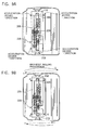
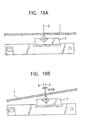
- Figs. 18A and 18B are explanatory views of "skew" phenomenon, in which Fig. 18A designates a case in which no skew is present, and Fig. 18B designates a case in which a skew is generated.
- Fig. 18A shows a case in which optical axis C of the object lens of an optical pickup system 2 correctly matches the normal line (the line perpendicular to the optical-disc surface) of an optical disc 1.
- Fig. 18B shows a case in which the optical disc 1 is tilted to cause the normal line P to be inclined against the optical axis C of the object lens of the optical pickup system 2, whereby resulting in the occurrence of the skew.
- Figs. 19A and 19B graphically designate variation of RF-jitter components (high-frequency jitter components) during the signal reproduction process in accordance with the variation of "skew".
- the expression “Rad” direction indicates a seek direction of the optical pickup system 2, i.e., the normal line direction of the track of the optical disc 1.
- the expression “Tan” direction indicates a tangential direction of the track of the optical disc 1.
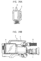
- Figs. 20A and 20B exemplify overall configuration of such a high-performance optical disc camcorder, in which Fig. 20A designates a rear view, whereas Fig. 20B designates a lateral view.
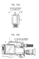
- Figs. 21A and 21B exemplify posture of image-pickup operation by way of actually using the optical-disc camcorder, in which Fig. 21A designates a rear view, whereas Fig. 21B designates a lateral view.
- any of conventional optical-disc camcorders has realized such a dimension and weight substantially being equivalent to those of any camera-combined VTR making use of a conventionally available videotape as a recording medium.
- the camera i.e., an optical-disc camcorder
- oscillation will act itself as rolling force in the direction R.
- the photographer performs image-pickup operation at a low angle while bearing the camera with his hands, oscillation similar to the above case will affect the camera body. This is called "rolling phenomenon" of the camera body.
- the rolling effect is transmitted to the base plate assembly (a mechanical block being composed of an optical pickup system, a seek mechanism thereof, a spindle-motor chucking mechanism and an optical disc) inside of the main body, whereby causing gyro-moment to act on an optical disc 8 being rotated inside of the main body to cause the optical disc 8 to be deformed as shown in Figs. 23A and 23B.
- X designates a horizontal axis against the camcorder main body 4 passing through the center of the rotation of the optical disc 8, where the horizontal axis X is in the direction identical to the optical axis of a camera lens 7 and also identical to the seek direction of the optical pickup system 2.
- Y designates a vertical axis against the camcorder main body 4 orthogonally intersecting the horizontal axis X via the center of the rotation of the optical disc 8.
- R designates a rolling direction
- J designates a direction in which a gyro moment is generated
- D designates a direction in which the optical disc 8 rotating in the direction S is deformed by the gyro moment.
- Fig. 23B shows an upper surface portion of the camcorder main body 4 shown in Fig. 23A, in which Z designates an axis of the rotation of the optical disc 8. Because of the deformation of the optical disc 8, the above-referred skew is generated between the optical axis of the object lens of the optical pickup system and the optical-disc recording surface, whereby resulting in the degraded signal recording and reproduction characteristics.
- any of the conventional optical-disc camcorders using an optical disc as the recording medium is subject to generation of rolling phenomenon to cause gyro-moment to affect the rotating optical disc to further cause the optical disc to be deformed, and yet, the rolling also causes spindle-motor shaft rotating itself in linkage with the optical disc to incur swing movement (or tilt).
- skew in other words, deflection in the perpendicularity
- swing movement of the spindle-motor shaft deflects track to result in the degraded tracking performance.
- any of the above-cited conventional optical-disc camcorders is subject to electrical control in order that distance between the object lens of the optical pickup system and the optical-disc surface can be held constant (in other words, within focal distance of the object lens, more precisely, within focal depth range) as of the condition in which the optical pickup system executing signal recording and reproduction is not in contact with the optical disc. Nevertheless, for any reason, if the optical disc ever deforms, perpendicularity between the optical axis of the object lens and the optical-disc recording surface deflects to cause skew to be generated. The skew gravely affects the signal recording and reproduction characteristic. In particular, it is known that, in the case of the optical disc camcorder, since rolling is generated during the image-pickup operation as was described above, gyro moment adversely affects the rotating optical disc to cause the optical disc to be deformed.
- the present invention has been devised in consideration of the above-referred conventional art.
- the object of the invention is to provide a novel optical disc camcorder which makes it possible to prevent rolling phenomenon generated in the camcorder body from being transmitted to the internally accommodated base plate assembly and also prevent skew phenomenon and swing movement of the spindle motor shaft from occurrence, whereby aiming at further improvement of the signal recording and reproduction characteristics and tracking performance as well.
- the invention provides a novel optical disc camcorder comprising a base plate assembly loaded with an optical disc and a camcorder main body accommodating the base plate assembly, where the base plate assembly is swingably secured to the camcorder main body via a horizontally rotating shaft and a weight is provided so that the center of the gravity of the base plate assembly is disposed below the above-referred horizontally rotating shaft.
- the horizontally rotating shaft is disposed between the interior portion of the camcorder main body and the base plate assembly. According to the horizontally rotating shaft, the base plate assembly is rotated in the direction of canceling rolling phenomenon, i.e., in the horizontal direction in which the rolling phenomenon mostly occurs while the optical disc camcorder is actually operated.
- the above-referred base plate assembly independently maintains stationary posture constantly being vertical to the ground. More specifically, even when the camcorder main body is rotated due to the rolling effect being generated, because of the relationship between the rotating shaft and the center of the gravity, it is possible for the base plate assembly to hold on vertically stationary posture against the ground surface by way of independently rotating itself in the direction to cancel the rolling phenomenon in the periphery of the rotating shaft without utilizing any specific drive mechanism.
- a locking mechanism is disposed in order to fixedly secure the base plate assembly to the camcorder main body whenever being required.
- provision of the locking mechanism prevents the base plate assembly from being rotated in the state in which no optical disc is present in the camcorder main body or power supply remains OFF inside of the main body, for example, whereby assuredly preventing the base plate assembly from being rotated unpreparedly in a case of other than image-pickup operation or reproduction of recorded data.
- a stopper means is provided in order to restrict a range of swing operation of the base plate assembly in the periphery of the rotating shaft and also absorb unwanted shock.
- stopper means such as a gear damper capable of attenuating and halting rotation of the base plate assembly beyond the maximum angle range for allowing rotary movement of the base plate assembly
- the base plate assembly can be prevented from rotating itself beyond a specific angle in the periphery of the above-referred rotating shaft, and yet, shock incidental to the halt of the rotation can also be absorbed.
- an acceleration sensor is provided for the optical-disc camcorder in order to detect the actual amount of acceleration of the rotation of the base plate assembly, and yet, a rotation drive mechanism is also provided so as to cause the base plate assembly to be rotated compulsorily in the periphery of the above-referred rotating shaft in correspondence with the value detected by the acceleration sensor.
- the above-referred structural example it is possible to detect acceleration degree (i.e., angular speed) at the time of causing the base plate assembly to rotate itself in the periphery of the above-referred rotating shaft. Further, whenever the rolling phenomenon has been generated in the camcorder main body, the above-referred rotation drive mechanism causes the base plate assembly to be rotated compulsorily in a direction of constantly canceling the acceleration amount into zero so that the base plate assembly can be prevented from rotating itself in pursuit of the rolling phenomenon.
- posture of the base plate assembly is properly controlled in order that the base plate assembly can maintain constant posture against the ground surface all the time.
- the present invention further provides a novel optical disc camcorder which comprises a base plate which is held inside of the camcorder main body via a damper and on which an optical-disc turn table, a spindle motor for activating rotation of the optical-disc turn table, an optical image pickup system and an optical pickup seek operation mechanism thereon, wherein: in conjunction with the above optical pickup seek operation mechanism, the above-referred optical image pickup system is mounted on a sub-base which is rotatably secured to the above-referred base plate.
- the novel optical disc camcorder related to the present invention further comprises a skew-correcting mechanism which corrects skew by causing the above-referred sub-base to rotate against the base plate fitted with the optical-disc turn table and the spindle motor.
- the optical pickup system and the seek mechanism thereof are disposed on the sub-base.
- the above-referred skew correcting mechanism executes angular control of the sub-base against the base plate having thereon the spindle motor which fixedly rotates the optical disc.
- a rotary shaft for operating the skew correcting mechanism is secured to an end point of the optical-disc turn table.
- a rotary shaft for angular control is secured to the end point of the optical-disc turn table.
- the optical disc is held being apart from the optical pickup system, whereby preventing the optical pickup system from being damaged via contact with the optical disc.
- the optical pickup system can be prevented from incurring damage otherwise caused by unwanted contact with the optical disc.
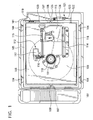
- Fig. 1 is a lateral view of a main body of the optical disc camcorder according to the first embodiment of the present invention.
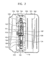
- Fig. 2 is a front view of the optical disc camcorder shown in Fig. 1.
- an optical disc camcorder main body (chassis) 101 internally comprises two parts including the one having an electrical printed wiring board 102 disposed thereon and the other one having an optical-disc drive unit 103 disposed thereon.
- the optical disc drive unit 103 is secured to the camcorder main body (chassis) 101 via a damper 104 which absorbs external oscillation and shock, where the damper 104 is secured to a sub-chassis 105.
- a pair of bearing units 107 are disposed on both sides of the sub-chassis 105 in the horizontal direction of the main body 101, whereby enabling a base plate assembly 106 to be rotated.
- a pair of rotary shafts 108 supporting the base plate assembly 106 are respectively disposed on both sides of the base plate assembly 106 and inserted into the bearing units 107 disposed on both sides of the sub-chassis 105.
- the base plate assembly 106 itself consists of a conventional optical disc drive unit.
- the base plate assembly 106 is fitted with an optical pickup unit 113 for executing signal recording and reproduction against an optical disc 109 via a spindle motor 111 attached with a turn table 110 for fixedly rotating the optical disc 109 and also via a seek-forwarding mechanism 112.
- the optical pickup unit 113 performs seeking operation in the radial direction of the optical disc 109 under guidance of a seek-directional guide shaft 114 secured onto the base plate assembly 106 via operation of the seek-forwarding mechanism 112 comprising a lead screw 115, a gear array 116, and a seek-drive motor 117.
- a weight 118 is secured to the base plate assembly 106 in order that center of the gravity of the entire base plate assembly 106 can be positioned lower than that of the above-referred rotary shaft 108.
- the base plate assembly 106 retains upright posture being perpendicular to the ground surface all the time.
- an oil gear damper 119 is secured to the base plate assembly 106 to function as stopper means.
- the oil gear damper 119 is brought into engagement with a stopper gear 120 secured to the sub-chassis 105 whenever angular deflection amount exceeds ⁇ 20 degrees between the optical disc camcorder main body 101 and the base plate assembly 106.
- a rotation locking mechanism 121 is secured to the sub-chassis 105 to function as the locking mechanism of the base plate assembly 106 against the sub-chassis 105 in a case where power supply remains OFF from the optical disc camcorder main body 101 or in such a case in which activation of the rolling-mode restricting mechanism is not desired. It is so arranged that the rotation locking mechanism 121 locks a locking shaft 122 secured to the base plate assembly 106 via a locking block 123, a locking arm 124 and locking spring 125. The locked condition is released by operating a locking-release solenoid 126.
- Figs. 3A and 3B respectively designate the principle for enabling the base plate assembly 106 to constantly maintain own stationary posture being perpendicular to the ground surface even when rolling phenomenon is generated in the optical disc camcorder main body 101.
- Fig. 3A shows a state where the optical disc camcorder main body 101 is inclined in the direction A due to the rolling phenomenon of the optical disc camcorder main body 101
- Fig. 3B shows a state where it is inclined in the direction B.
- the base plate assembly 106 freely rotates itself in the periphery of the rotary shaft 108 with regard to the sub-chassis 105, whenever the camcorder main body 101 inclines itself in the direction A, the base plate assembly 106 inclines itself in the direction inverse from the direction A with regard to the sub-chassis 105, whereby enabling the base plate assembly 106 to always maintain own stationary posture being perpendicular to the ground surface, as shown in Fig. 3A.
- the same rule applies to a case in which the camcorder main body 101 inclines itself in the direction B being inverse from the direction A shown in Fig. 3B.
- the base plate assembly 106 can always preserve own stationary posture constant.
- rolling phenomenon generated in the optical disc camcorder main body 101 is identified to be a maximum of 4Hz within ⁇ 15 degrees of range.
- tilt of the camcorder main body 101 is identified to be within 0 ⁇ 5 degrees of range.
- the present invention provides the oil-gear-damper 119 being secured to the base plate assembly 106 and also the stopper gear 120 being secured to the sub-chassis 105 as practical means to stop rotation with regard to chassis of the base plate assembly 106.
- Figs. 4A and 4B are views respectively explaining the operation of the stopper mechanism comprising the oil-gear-damper 119.
- Fig. 4A shows a state where the camcorder main body 101 is inclined in the direction due to the rolling phenomenon of the camcorder main body 101
- Fig. 4B shows a state where it is inclined in the direction B.
- the oil-gear-damper 119 is brought into engagement with the stopper gear 120 at the position E (shown in Fig.
- Figs. 5A and 5B are respectively explanatory of the mechanism for locking rotation of the base plate assembly 106 with regard to the sub-chassis 105.
- the base plate assembly 106 freely rotates itself with regard to the rotary shaft 108 while power is turned OFF from the camcorder main body 101, because of shock being added on the way of carrying the camcorder main body 101, the base plate assembly 106 may incur unwanted damage.
- inserting or ejecting an optical disc (cartridge) 109 into or out from the camcorder main body 101 handling convenience is much better when the base plate assembly 106 is fixed to the sub-chassis 105.
- the rotation locking mechanism 121 locks the rotation of the base plate assembly 106 with regard to the sub-chassis 105.
- resilient force energized by locking spring 125 is transmitted in the direction A to cause the locking block 123 to be shifted in the direction B via the locking arm 124. This in turn causes the locking shaft 122 provided for the base plate assembly 106 to be fixed, whereby locking the rotation of the base plate assembly 106.
- resilient force energized by solenoid 126 is transmitted in the direction C to cause the locking block 123 to be shifted in the direction D, whereby freeing the locking shaft 123 to enable the base plate assembly 106 to be rotated in the direction E.
- the present invention even when rolling phenomenon is generated inside of the optical disc camcorder body, by way of causing the base plate assembly to independently rotate itself inside of the camcorder body via the relationship between the position of the center of the gravity and the rotary shaft, the rolling phenomenon is not transmitted to inside of the main body and the optical disc remains totally being free from gyro moment internally being generated.
- Fig. 6 is a lateral view of structural components of the optical disc camcorder according to the second embodiment of the present invention.
- Fig. 7 is a front view of the optical disc camcorder shown in Fig. 6.
- an optical disc camcorder 201 comprises two parts including the one having an electrical printed wiring board 202 disposed thereon and the other one having an optical disc drive unit 203 disposed thereon.
- the optical disc drive unit 203 is secured to a chassis 201 via a damper 204 which absorbs oscillation and shock from external source.
- the damper 204 is secured to a sub-chassis 205 whose both-side portions respectively have a bearing unit 207 enabling the base plate assembly 206 to be rotated in the horizontal direction of the main body 201.
- a pair of rotary shafts 208 disposed on both sides of the base plate assembly 206 respectively are accommodated in the bearings 207 disposed on both sides of the sub-chassis 205.
- the base plate assembly 206 consists of a conventional optical disc drive unit, which comprises a spindle motor 211 attached with a turn table 210 for fixedly rotating the optical disc 209 and an optical image pickup system 213 for recording and reproducing signal onto and from the optical disc 209 via seek-forwarding mechanism 212.
- the optical pickup system 213 Under the guidance of a guide shaft 214 secured onto the base plate assembly 206, the optical pickup system 213 performs seek operation in the radial direction of the optical disc 209 via the seek-forwarding mechanism 212 comprising a lead screw 215, a gear array 216 and a seek-drive motor 217.
- the base plate assembly 206 is fitted with an upper angular-speed (i.e., acceleration degree) sensor 218 being disposed above the rotary shaft 208 at a specific position extended from the spindle motor 211 and a lower angular-speed (i.e., acceleration degree) sensor 219 disposed below the rotary shaft 208.
- the upper and lower sensors 218 and 219 respectively measure angular speed (acceleration degree) of the base plate assembly 206 generated in the periphery of the rotary shaft 208.
- the sub-chassis 205 is fitted with a rolling-cancel mechanism 220.
- a stationary gear 221secured to the base plate assembly 206 is driven by a gear array 222 comprising a flat gear, a worm gear, and a worm wheel via a drive motor 223.
- Figs. 8A and 8B are views respectively explaining the operation of the above-referred rolling-mode cancel mechanism 220.
- Fig. 8A designates a state in which the optical disc camcorder main body 201 is inclined in the direction S.
- the angular speed sensors 218 and 219 secured to the base plate assembly 206 jointly measure the angular speed in the direction A at the upper portion of the rotary shaft 208 and the angular speed in the direction B at the lower portion of the rotary shaft 208.
- the rolling-mode cancel mechanism 220 causes the base plate assembly 206 to be rotated in the direction D with regard to the sub-chassis 208 by pivoting on the rotary shaft 208 to enable the base plate assembly 206 to hold on stationary posture being vertical to the ground surface all the time.
- Fig. 8B designates a case in which the optical disc camcorder 201 is inclined in the direction T being inverse from the direction S shown in Fig. 8A.
- Rolling mode designates such a phenomenon in which the tilt in the directions S and T alternately occurs in succession.
- the base plate assembly 206 maintains constant (vertical) posture all the time.
- the rolling-mode cancel mechanism 220 controls posture of the base plate assembly 206 so that the angular-speed sensors 218 and 219 does not measure actual angular speed all the time, in other words, in order that the angular-speed sensors 218 and 219 will constantly indicate value 0.
- Figs. 9A and 9B respectively designate definition of the direction of angular speed being detected by the above-referred upper and lower angular-speed sensors 218 and 219 and the definition of the positive and negative codes shown therein.
- the direction + corresponds to the direction in which the base plate assembly 206 rotates in the clockwise direction with regard to the rotary shaft 208.
- the upper sensor 218 measures angular speed of the base plate assembly 206 in the direction A
- the lower sensor 219 measures angular-speed of the same in the direction B.
- the upper sensor 218 measures the angular-speed of the base plate assembly 206 in the direction -A
- the lower sensor 219 measures the angular-speed of the same in the direction -B.
- the upper and lower angular-speed sensors 218 and 219 jointly measures the angular-speed value based on the identical code.
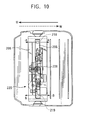
- Fig. 10 designates the horizontal movement of the optical disc camcorder main body 201 without requiring posture control in contrast to the above-referred rolling mode requiring posture control.
- the reference codes "U” and “W” show the movement of the main body in a horizontal direction.
- measured values of the upper and lower angular-speed sensors 218 and 219 are respectively designated by the positive and negative codes being inverse from each other.
- the rolling-mode cancel mechanism 220 does not perform control of posture of the base plate assembly 206.
- the rolling-mode cancel mechanism 220 enables the posture of the base plate assembly 206 to be held on constantly being vertical to the ground surface by arranging that the above-referred acceleration sensors 218 and 219 will be able to constantly output value 0.
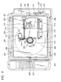
- Fig. 11 is a lateral view of the main body of the optical disc camcorder according to the third embodiment of the present invention.
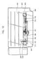
- Fig. 12 is a plan view showing the top view of the inventive optical disc camcorder shown in Fig. 11.
- the interior of the optical disc camcorder main body 301 consists of two parts including the one having an electrical substrate 302 disposed thereon and the other one having the optical disc drive unit 303 disposed thereon.
- the optical disc drive unit 303 is secured to a chassis 301 via a damper 304 which absorbs oscillation and shock from external source.
- a base plate 305 to which the damper 304 is secured is disposed with a spindle motor 308 attached with a turn table 307 which fixedly rotates an optical disc 306; an active SKEW correcting mechanism 309 according to the present invention; an optical pickup system 310, a seek mechanism 311 which causes the optical pickup system 310 to perform seek operation in the radial direction of the optical disc 306; and a sub-base rotation shaft bearing 313 which makes up the rotary shaft of a sub-base assembly 312 mounting the seek mechanism 311.
- the active SKEW correcting mechanism 309 comprises a drive motor 314, a cam gear unit 315 having an inner surface being formed into cam shape for driving the sub-base 312 and a holding substrate 316 which secures the cam gear unit 315 onto the base plate 305.
- the optical pickup system 310 is mounted with an LED-reflective type SKEW sensor 317 for measuring the amount of skew generated between the optical axis of the object lens and the optical-disc surface.
- the optical pickup system 310 performs seek operation via the seek mechanism 311 consisting of a lead screw 319, a gear array 320, and a seek-drive motor 321.
- a sub-base rotary axial shaft 322 functioning as the axis for correcting skew is secured to the sub-base 312 in the vertical direction. Further, a skew drive shaft 323 making up operating origin in the course of correcting skew is engaged with the cam gear 315. Based on the above mechanical arrangement, by way of pivoting on the sub-base rotation shaft bearing 313 provided on the base plate 305, angular control for correcting the skew is executed by the active SKEW correcting mechanism 309.
- Figs. 13A and 13B are views respectively explaining the operation of the active SKEW correcting mechanism 309.
- gyro moment acts on the rotating optical disc to cause deformation of the disc.
- the active SKEW correcting mechanism 309 pertaining to the invention controls the amount of skew generated between the optical axis of the object lens and the optical disc surface so that it will remain being zero all the time.
- Fig. 13A designates such a case in which the optical disc 306 is deformed in the direction P being apart from the optical pickup system 310. In this case, the active SKEW correcting mechanism 309 drives the optical pickup system 310 in the direction E being closer to the optical disc 306. Conversely, Fig. 13B designates such a case in which the optical disc 306 is deformed in the direction Q being closer to the optical pickup system 310. In this case, the active SKEW correcting mechanism 309 drives the optical pickup system 310 in the direction F being apart from the optical disc 306.
- Fig. 14 is a simplified block diagram being explanatory of the method of controlling drive operation of the SKEW correcting mechanism 309.
- Amount of skew generated between the optical pickup system 310 and the surface of the optical disc 306 is measured by the skew sensor 317 secured to a position close to the object lens of the optical pickup system 310.
- Fig. 15 designates the actual result of the measurement of the displaced amount of the optical disc 306 subsequent to generation of the rolling phenomenon corresponding to approximately 4Hz/15 degrees in the actually operable optical disc camcorder main body.
- the deformation of the optical disc 306 generated by gyro moment resulted in the monotonous displacement of the optical disc 306 by about 0.8 degree in the radial direction from the end point of the turn table 307, to which the optical disc 306 is secured, as a fulcrum.
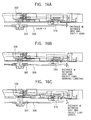
- Figs. 16A to 16C are explanatory views of the variation of distance between the optical disc 306 and an object lens.
- Fig. 16A designates a state in which the optical disc 306 remains free from being deformed.
- Fig. 16B designates a case in which the rotary axial position of the SKEW correcting mechanism 309 is set to the end point of the turn table 307.
- Fig. 16C designates a state in which the rotary axial position of the SKEW correcting mechanism 309 is set to the intermediate circumferential portion being outer from the turn table 307.
- Figs. 17A and 17B are views respectively explaining the inventive method for preventing the optical pickup system (in particular, the object lens) from being brought into contact with cartridge in a case of inserting or ejecting the optical disc (or cartridge) into or out from the optical disc camcorder body 301 by way of utilizing the active SKEW correcting mechanism 309 featuring the present invention.
Landscapes
- Engineering & Computer Science (AREA)
- Multimedia (AREA)
- Signal Processing (AREA)
- Optical Recording Or Reproduction (AREA)
- Studio Devices (AREA)
- Holding Or Fastening Of Disk On Rotational Shaft (AREA)
Abstract
Description
Claims (7)
- An optical disc camcorder comprising a base plate assembly internally loaded with an optical disc and a camcorder main body accommodating said base plate assembly, wherein:said base plate assembly is swingably secured to said camcorder main body via a horizontal-directional rotary shaft; andsaid base plate assembly is provided with a weight so that center of gravity of said base plate assembly is set below said rotary shaft.
- The optical disc camcorder according to Claim 1, further comprising a locking mechanism for fixedly securing said base plate assembly to said optical disc camcorder main body whenever necessary.
- The optical disc camcorder according to Claim 1, further comprising a stopper means for restricting range of swing movement of said base plate assembly in the periphery of said rotary shaft and also for absorbing shock.
- An optical disc camcorder comprising a base plate assembly internally loaded with an optical disc and a camcorder main body accommodating said base plate assembly, wherein:said base plate assembly is swingably secured to said camcorder main body via a horizontal-directional rotary shaft; andsaid base plate assembly is provided with an acceleration sensor for detecting degree of acceleration performed by said base plate assembly and a rotation drive mechanism for causing said base plate assembly to be rotated compulsorily in the periphery of said rotary shaft in response to the value detected by said acceleration sensor.
- An optical disc camcorder comprising a base plate being secured inside of said camcorder main body via damper and fitted with a turn table for rotating an optical disc, a spindle motor for rotating said turn table, an optical pickup system, and a seek operation mechanism provided for said optical pickup system, wherein:said optical pickup system and said seek operation mechanism are mounted on a sub-base rotatably being secured to said base plate with a rotary axial shaft; andsaid optical disc is further provided with a skew sensor for detecting skew and a skew correcting mechanism for driving said sub-base to be rotated in a direction for canceling the skew in accordance with an output from the skew sensor.
- The optical disc camcorder according to Claim 5, further comprising a rotary shaft for correcting skew at an end point of said turn table.
- The optical disc camcorder according to Claim 5, wherein said skew correcting mechanism controls a position of said optical pickup system so as not to come into contact with an optical disc.
Applications Claiming Priority (2)
| Application Number | Priority Date | Filing Date | Title |
|---|---|---|---|
| JP27691799A JP4192355B2 (en) | 1999-09-29 | 1999-09-29 | Optical disc camcorder |
| JP27691799 | 1999-09-29 |
Publications (3)
| Publication Number | Publication Date |
|---|---|
| EP1098323A2 true EP1098323A2 (en) | 2001-05-09 |
| EP1098323A3 EP1098323A3 (en) | 2001-12-19 |
| EP1098323B1 EP1098323B1 (en) | 2003-11-12 |
Family
ID=17576203
Family Applications (1)
| Application Number | Title | Priority Date | Filing Date |
|---|---|---|---|
| EP00402689A Expired - Lifetime EP1098323B1 (en) | 1999-09-29 | 2000-09-29 | Optical disc camcorder |
Country Status (6)
| Country | Link |
|---|---|
| US (1) | US7283730B1 (en) |
| EP (1) | EP1098323B1 (en) |
| JP (1) | JP4192355B2 (en) |
| KR (1) | KR20010030526A (en) |
| CN (1) | CN1300074A (en) |
| DE (1) | DE60006477T2 (en) |
Cited By (1)
| Publication number | Priority date | Publication date | Assignee | Title |
|---|---|---|---|---|
| EP1517315A3 (en) * | 2003-09-22 | 2007-11-07 | Sony Corporation | Skew control method and skew control unit |
Families Citing this family (9)
| Publication number | Priority date | Publication date | Assignee | Title |
|---|---|---|---|---|
| US7266073B2 (en) | 2003-05-08 | 2007-09-04 | Matsushita Electric Industrial Co., Ltd. | Optical disc apparatus, camera apparatus, and method for controlling light emission operation |
| JP2004343364A (en) * | 2003-05-15 | 2004-12-02 | Hitachi Ltd | Optical disk video camera |
| JP2005063558A (en) * | 2003-08-12 | 2005-03-10 | Sony Corp | Disc recording and / or playback device |
| JP2005063560A (en) * | 2003-08-12 | 2005-03-10 | Sony Corp | Disc recording and / or playback device |
| US20050147397A1 (en) * | 2003-12-17 | 2005-07-07 | Sony Corporation | Image pickup apparatus |
| JP2006140751A (en) * | 2004-11-12 | 2006-06-01 | Hitachi Ltd | Disc video camera |
| JP2006157472A (en) * | 2004-11-30 | 2006-06-15 | Hitachi Ltd | Optical disc video camera |
| JP4375470B2 (en) * | 2007-09-28 | 2009-12-02 | ソニー株式会社 | Optical disk drive apparatus, camera apparatus, and optical beam tilt control method following optical disk skew |
| JP2011065712A (en) * | 2009-09-17 | 2011-03-31 | Mitsubishi Electric Corp | Relative position detector, damping device equipped with the relative position detector, and disk device |
Family Cites Families (8)
| Publication number | Priority date | Publication date | Assignee | Title |
|---|---|---|---|---|
| JPH055740Y2 (en) * | 1986-12-18 | 1993-02-15 | ||
| JPH03273769A (en) * | 1990-01-16 | 1991-12-04 | Hitachi Ltd | VTR integrated camera |
| US6141034A (en) * | 1995-12-15 | 2000-10-31 | Immersive Media Co. | Immersive imaging method and apparatus |
| US5881034A (en) | 1996-08-20 | 1999-03-09 | Sony Corporation | Apparatus for driving objective lens |
| SG65872A1 (en) | 1996-11-20 | 1999-06-22 | Omni Peripherals Pte Ltd | A floating frame for optical storage device loading mechanism |
| JPH10191224A (en) | 1996-12-24 | 1998-07-21 | Sony Corp | Camera-integrated video recorder |
| JP3504110B2 (en) | 1997-06-25 | 2004-03-08 | 株式会社東芝 | Optical disk drive |
| US6628338B1 (en) * | 1998-07-08 | 2003-09-30 | Elbex Video Ltd. | Direct drive electric motor apparatus incorporating slip ring assembly |
-
1999
- 1999-09-29 JP JP27691799A patent/JP4192355B2/en not_active Expired - Fee Related
-
2000
- 2000-09-28 US US09/671,688 patent/US7283730B1/en not_active Expired - Fee Related
- 2000-09-28 KR KR1020000056985A patent/KR20010030526A/en not_active Withdrawn
- 2000-09-29 EP EP00402689A patent/EP1098323B1/en not_active Expired - Lifetime
- 2000-09-29 DE DE60006477T patent/DE60006477T2/en not_active Expired - Fee Related
- 2000-09-29 CN CN00134708A patent/CN1300074A/en active Pending
Cited By (2)
| Publication number | Priority date | Publication date | Assignee | Title |
|---|---|---|---|---|
| EP1517315A3 (en) * | 2003-09-22 | 2007-11-07 | Sony Corporation | Skew control method and skew control unit |
| US7394737B2 (en) | 2003-09-22 | 2008-07-01 | Sony Corporation | Skew control method and skew control unit |
Also Published As
| Publication number | Publication date |
|---|---|
| DE60006477D1 (en) | 2003-12-18 |
| EP1098323B1 (en) | 2003-11-12 |
| JP2001101855A (en) | 2001-04-13 |
| KR20010030526A (en) | 2001-04-16 |
| EP1098323A3 (en) | 2001-12-19 |
| DE60006477T2 (en) | 2004-08-26 |
| CN1300074A (en) | 2001-06-20 |
| US7283730B1 (en) | 2007-10-16 |
| JP4192355B2 (en) | 2008-12-10 |
Similar Documents
| Publication | Publication Date | Title |
|---|---|---|
| US6052357A (en) | Compact optical disk apparatus having a swing-motion optical head | |
| EP1098323B1 (en) | Optical disc camcorder | |
| US5761182A (en) | Optical recording and reproducing apparatus | |
| JP3035223B2 (en) | Pickup position adjustment device for disc player | |
| EP1367585B1 (en) | Disk device | |
| US20020071357A1 (en) | Optical pick-up device | |
| JPH10191224A (en) | Camera-integrated video recorder | |
| US20060190953A1 (en) | Disk recording/reproducer and method for fixing pickup of disc recorder/reproducer | |
| JP3731445B2 (en) | Disc player and initial adjustment method | |
| WO1996018190A1 (en) | Optical pickup driving device for optical disk | |
| EP1792313B1 (en) | Optical disc system with an adjustable position of the rotating disc | |
| US20050240954A1 (en) | Disk drive unit, and information recording and regeneration apparatus | |
| WO2004044906A1 (en) | Optical disk drive device and method of correcting tilt of optical pickup | |
| US6747925B2 (en) | Method and system for generating a center error signal in an optical storage system | |
| JPH077525B2 (en) | Optical beam tilt correction device | |
| JP4155726B2 (en) | Optical disk drive device | |
| JP2001101675A (en) | Optical disc camcorder | |
| US8341657B2 (en) | Lens driving mechanism for optical pickup and optical disc apparatus | |
| KR20050095262A (en) | Method for compensating tilt and optical recording and/or reproducing apparatus applied the same | |
| JPH0454296B2 (en) | ||
| JP4196807B2 (en) | Disk device and imaging device including the disk device | |
| JP2002100129A (en) | Optical disk drive | |
| JP2001101776A (en) | Optical disc camcorder | |
| JP2006179103A (en) | Disk unit | |
| JP2006031826A (en) | Optical disc apparatus and method for assembling the same |
Legal Events
| Date | Code | Title | Description |
|---|---|---|---|
| PUAI | Public reference made under article 153(3) epc to a published international application that has entered the european phase |
Free format text: ORIGINAL CODE: 0009012 |
|
| AK | Designated contracting states |
Kind code of ref document: A2 Designated state(s): DE FR GB Kind code of ref document: A2 Designated state(s): AT BE CH CY DE DK ES FI FR GB GR IE IT LI LU MC NL PT SE |
|
| AX | Request for extension of the european patent |
Free format text: AL;LT;LV;MK;RO;SI |
|
| PUAL | Search report despatched |
Free format text: ORIGINAL CODE: 0009013 |
|
| AK | Designated contracting states |
Kind code of ref document: A3 Designated state(s): AT BE CH CY DE DK ES FI FR GB GR IE IT LI LU MC NL PT SE |
|
| AX | Request for extension of the european patent |
Free format text: AL;LT;LV;MK;RO;SI |
|
| RIC1 | Information provided on ipc code assigned before grant |
Free format text: 7G 11B 31/00 A, 7G 11B 33/08 B |
|
| RAP1 | Party data changed (applicant data changed or rights of an application transferred) |
Owner name: SONY CORPORATION |
|
| 17P | Request for examination filed |
Effective date: 20020612 |
|
| 17Q | First examination report despatched |
Effective date: 20020724 |
|
| AKX | Designation fees paid |
Free format text: DE FR GB |
|
| GRAH | Despatch of communication of intention to grant a patent |
Free format text: ORIGINAL CODE: EPIDOS IGRA |
|
| GRAS | Grant fee paid |
Free format text: ORIGINAL CODE: EPIDOSNIGR3 |
|
| GRAA | (expected) grant |
Free format text: ORIGINAL CODE: 0009210 |
|
| AK | Designated contracting states |
Kind code of ref document: B1 Designated state(s): DE FR GB |
|
| PG25 | Lapsed in a contracting state [announced via postgrant information from national office to epo] |
Ref country code: FR Free format text: LAPSE BECAUSE OF FAILURE TO SUBMIT A TRANSLATION OF THE DESCRIPTION OR TO PAY THE FEE WITHIN THE PRESCRIBED TIME-LIMIT Effective date: 20031112 |
|
| REG | Reference to a national code |
Ref country code: GB Ref legal event code: FG4D |
|
| REF | Corresponds to: |
Ref document number: 60006477 Country of ref document: DE Date of ref document: 20031218 Kind code of ref document: P |
|
| REG | Reference to a national code |
Ref country code: IE Ref legal event code: FG4D |
|
| PLBE | No opposition filed within time limit |
Free format text: ORIGINAL CODE: 0009261 |
|
| STAA | Information on the status of an ep patent application or granted ep patent |
Free format text: STATUS: NO OPPOSITION FILED WITHIN TIME LIMIT |
|
| PG25 | Lapsed in a contracting state [announced via postgrant information from national office to epo] |
Ref country code: GB Free format text: LAPSE BECAUSE OF NON-PAYMENT OF DUE FEES Effective date: 20040929 |
|
| 26N | No opposition filed |
Effective date: 20040813 |
|
| EN | Fr: translation not filed | ||
| PG25 | Lapsed in a contracting state [announced via postgrant information from national office to epo] |
Ref country code: DE Free format text: LAPSE BECAUSE OF NON-PAYMENT OF DUE FEES Effective date: 20050401 |
|
| GBPC | Gb: european patent ceased through non-payment of renewal fee |
Effective date: 20040929 |
|
| REG | Reference to a national code |
Ref country code: IE Ref legal event code: MM4A |