EP1098166A2 - Method and apparatus for thickness measurement on transparent films - Google Patents
Method and apparatus for thickness measurement on transparent films Download PDFInfo
- Publication number
- EP1098166A2 EP1098166A2 EP00122582A EP00122582A EP1098166A2 EP 1098166 A2 EP1098166 A2 EP 1098166A2 EP 00122582 A EP00122582 A EP 00122582A EP 00122582 A EP00122582 A EP 00122582A EP 1098166 A2 EP1098166 A2 EP 1098166A2
- Authority
- EP
- European Patent Office
- Prior art keywords
- objective
- film
- camera
- transparent
- thickness
- Prior art date
- Legal status (The legal status is an assumption and is not a legal conclusion. Google has not performed a legal analysis and makes no representation as to the accuracy of the status listed.)
- Granted
Links
Images


Classifications
-
- G—PHYSICS
- G01—MEASURING; TESTING
- G01B—MEASURING LENGTH, THICKNESS OR SIMILAR LINEAR DIMENSIONS; MEASURING ANGLES; MEASURING AREAS; MEASURING IRREGULARITIES OF SURFACES OR CONTOURS
- G01B11/00—Measuring arrangements characterised by the use of optical techniques
- G01B11/02—Measuring arrangements characterised by the use of optical techniques for measuring length, width or thickness
- G01B11/06—Measuring arrangements characterised by the use of optical techniques for measuring length, width or thickness for measuring thickness ; e.g. of sheet material
- G01B11/0616—Measuring arrangements characterised by the use of optical techniques for measuring length, width or thickness for measuring thickness ; e.g. of sheet material of coating
Definitions
- the invention concerns a method and an apparatus for thickness measurement on transparent films, having the features of independent Claims 1 and 5.
- the invention is used for thickness measurement on transparent, partially reflective films. It is intended in particular to be used in blood analysis, which is based, inter alia, on the quantitative evaluation of fluorescence intensities of a blood film. An essential prerequisite for the evaluation is an accurate knowledge of the thickness of the blood film.
- the blood is present in a special single-use microcuvette made of glass or plastic or a glass/plastic combination. Production-related tolerances in the dimensions of the single-use microcuvette make it necessary to measure the thickness of the blood film at different points on the already filled single-use microcuvette.
- the thickness tolerances of the single-use microcuvette for example, with a mechanical feeler.
- the thickness of the blood film is determined, however, by the inside dimensions of the single-use microcuvette, which may have tolerance deviations different from those of the outside dimensions. But because the feeler can sense only the outside dimensions, it is unsuitable for determining the thickness of the blood film.
- Another method for monitoring the thickness tolerances of the single-use microcuvette consists in an interferometric measurement of the blood film. This is done, for example, by using an interferometer arrangement in a reflected-light microscope whose illumination light is conveyed out of a spectrometer.
- the filled single-use microcuvette is placed, in the interferometer beam, on the object stage of the microscope.
- the microscope illumination light is reflected and interfered with at all the interfaces of the single-use microcuvette.
- the measurement is performed for various wavelengths of the illumination light furnished by the spectrometer. If the refractive index is known, the thickness of the individual films can be determined from the interference values as a function of wavelength. In analyzing the measurements, however, it proves very difficult to separate out the light components reflected from the various interfaces.
- a further disadvantage is the need for a spectrometer, which is costly and requires a great deal of space.
- a focusing aid is arranged in an illumination beam of an objective in a position conjugated with the focal plane.
- the focal plane is imaged on a camera.
- the focusing aid is imaged sharply on the camera only when a partially reflective interface of an object is in the focal plane.
- the sharpness of the image of the focusing aid, monitored with the camera, thus serves as a "focus indicator".
- the invention makes use of this to determine the film thicknesses.
- the illumination beam is directed through the objective onto an object that has a transparent film.
- the object used is, for example, a single-use microcuvette for blood analysis that is filled with a transparent blood film. Alternatively, it would also be possible to use an object support that carries a transparent blood film.
- the focal plane of the objective is displaced stepwise through the object.
- the values of the stop positions Z i are measured.
- a camera image is recorded and its focal score is determined, the image of the structure of the focusing aid being used as sharpness indicator.
- the structure on the focusing aid is at least one bar whose bar length is a multiple of the bar width; the bar width must be a multiple of the resolution capability of the objective and the camera. Multiple bars can also be used. It is advantageous to use a cross having, for the individual ends of the cross, the dimensions discussed for the bar. The cross can be adapted to different pixel widths and heights.
- a low focus score results from unsharpness of the image; a high focus score results from good sharpness of the image.
- the focus score has a relative maximum.
- the maxima of the focus scores are therefore determined.
- the positions Z i having maximal focus scores are assigned to the locations of the various interfaces of the object. Interfaces are, for example in the case of a microcuvette filled with liquid, the air-glass transitions, the glass-liquid transitions, the liquid-glass transitions, and the glass-air transitions.
- the various interfaces differ greatly in terms of reflectivity.
- Glass-air interfaces for example, reflect more strongly (by a factor of about 10) than glass-liquid interfaces. Because the reflection intensities are incorporated into the calculation when identifying the focus scores, it is possible to draw conclusions from the magnitudes of the identified focus scores as to the kind of interface, and thus to make an assignment.
- the thickness of the transparent film e.g. of the liquid in the microcuvette, is then calculated from the difference between the positions z i assigned to their interfaces z 1 , z 2 .
- the method according to the present invention can reliably be used for thickness measurement on transparent films of all kinds.
- the transparent films can be:
- the films, the substrate, and any covering layers must have smooth surfaces.
- the interfaces of the films must be only partially reflective, i.e. they can have very small differences in refractive index. Even the low levels of reflection resulting from these interfaces are sufficient for automatic image evaluation using image analysis as described by the method according to the present invention.
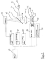
- FIG. 1 shows an apparatus for carrying out the method according to the present invention. What is being examined is an object 1 that has a transparent film 2 whose thickness is to be determined.
- An illumination beam 4 proceeds from a light source 3 and is directed through an objective 5 onto object 1; optical axis 6 of illumination beam 4 is oriented perpendicular to film 2. Deflection of illumination beam 4 toward object 1 takes place in a beam splitter 7.
- a focusing aid 9 equipped with structures is arranged in a location conjugated with focal plane 8 of objective 5.
- focal plane 8 lies at the upper interface of a transparent film 2.
- This transparent film 2 is enclosed in object 1.
- object 1 comprises a baseplate 10 which has a cavity in which transparent film 2 is located. Resting on baseplate 10 is a transparent cover 11 that sealingly closes off the cavity having transparent film 2.
- An imaging beam 12 proceeds from the upper interface of transparent film 2, i.e. from focal plane 8. It passes through beam splitter 7 and is directed onto a camera 13 that is located in a position conjugated with focal plane 8.
- the structure of focusing aid 9 is sharply imaged onto camera 13 with imaging beam 12 only if focal plane 8 lies in an interface of object 1 (as shown in the depiction). If focal plane 8 lies outside an interface of object 1, the structure of focusing aid 9 appears unsharp in the camera image. The invention makes use of this fact.
- Object 1 is joined to a drive unit 14 with which object 1 can be displaced in the Z direction relative to objective 5.
- focal plane 8 can be passed in succession through all the interfaces of object 1.
- a sharp image is produced on camera 13 only when passing through an interface. From the difference between the Z positions associated with the specific interfaces, a desired film thickness can then be determined.
- drive unit 14 is joined to a Z-position measurement unit 15 which measures the current position z i of object 1.
- Camera 13 is connected to an image recording unit 16, and the latter in turn to an image processing unit 17 and a calculating unit 18.
- Drive unit 14, Z-position measurement unit 15, image recording unit 16, image processing unit 17, and calculation unit 18 are connected to a control unit 19 with which execution of the process steps is controlled.
- Object 1 is illuminated with illumination beam 4 guided through objective 5; object 1 is in an initial position in which, in this example, focal plane 8 lies above the uppermost delimiting surface of transparent covering 11.
- the image of camera 13 is recorded by image recording unit 16. Since focal plane 8 is not located in a partially reflective interface of object 1, focusing aid 9 is imaged unsharply on camera 13.
- a focus score f(z i ) for the recorded camera image is determined using image processing unit 17.
- z i indicates the current position of object 1, which is determined using Z-position measurement unit 15.
- This procedure of recording a camera image and determining an associated focus score f(z i ) is then performed for various positions z i of object 1 relative to objective 5.
- image processing unit 17 For each camera image recorded in the individual stop positions z i , image processing unit 17 is used to identify a focus score f(z i ). The focus scores f(z i ) thus obtained are evaluated using calculation unit 18, by determining the various maxima of the focus scores f(z i ). Once determined, the maxima are assigned to the interfaces of object 1. A value of the associated z i position can then be assigned to each maximum.
- FIG. 2 shows an enlarged detail of object 1. This is, for example, a section through a liquid-filled microcuvette, in turn depicting a baseplate 10 having a cavity that contains a transparent film 2, in this example a liquid. Baseplate 10 is covered by a transparent covering 11 in such a way that its cavity is sealingly closed off.
- the depiction contains arrows whose size and line thickness schematically represent, by their direction and intensity, the reflected light components occurring at the individual interfaces of object 1.
- the reflected light components are symbolized by the upward-pointing arrows, and the illumination light by the thick arrow pointing downward.
- This graphically indicates that the strongest reflections occur at the glass-air interfaces, i.e. at the top and bottom sides of object 1.
- the reflected light components are substantially smaller at the upper and lower interfaces of the transparent liquid film that is being measured. It is evident that the various interfaces differ greatly in terms of their reflectivity: glass-air transitions reflect more strongly, by a factor of about 10, than glass-liquid transitions. Since it is possible, when determining the focus score, to evaluate the intensity of the camera image along with each recorded camera image, conclusions as to the location of the interfaces can be drawn from the values of the focus scores.
- n is the number of pixels per line and m the number of pixels per column.
- I n and I m respectively indicate the intensities of two adjacent pixels n, m. Because the exponent x > 1 is applied to the intensity differences
- FIG. 3 shows a measurement series of camera images recorded for various z i positions of object 1. It is evident that a cross was used as the structure of focusing aid 9.
- the cross is imaged with different degrees of sharpness and brightness, i.e. with differing light intensity. Since focusing aid 9 is imaged sharply on the camera only if focal plane 8 is located in an interface of object 1, the intensity and sharpness of the cross in the camera image serve as the focus criterion. The cross must therefore be considerably larger in relation to the pixel widths and heights of the camera.
- the cross appears extremely unsharp, meaning that focal plane 8 is located far away from an interface of object 1.
- camera images 2, 3, and 4 proceeding to the right
- the sharpness of the cross progressively improves. This means that at the positions z i occupied in these images, focal plane 8 was moved progressively closer to an interface of object 1.
- the fifth camera image shows the greatest sharpness for the cross of focusing aid 9; for all further camera images, the cross again becomes less sharp.
- camera image 5 was recorded in a z i position in which an interface of object 1 lay in focal plane 8.
- a focus score f(z i ) is determined for each camera image using the function described above.
- the highest focus score f(z i ) is calculated for camera image 5, while correspondingly lower values for f(z i ) are found for the other camera images in accordance with their sharpness and light intensity.
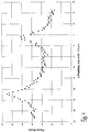
- FIG. 4 shows a diagram of a measurement series of calculated focus scores as a function of stop positions z i of object 1.
- the focus scores shown exhibit maximum values for two ranges of positions z i . At the left maximum, one focus score itself is obviously the maximum. At the right maximum, the measured focus scores cluster around the actual maximum; in other words the position of maximum image sharpness was not stopped at. Determination of the actual maxima of the focus scores can therefore be greatly improved with a sufficiently small interval when displacing object 1 with respect to objective 5.
- the thickness of the film being investigated is then calculated from the difference between the two maxima.
- the maxima depicted in FIG. 4 lie approximately 30 ⁇ m apart.
- the two maxima shown here were unequivocally associated, in a measurement, with the interfaces of transparent film 2 that is being measured, so that the thickness of transparent film 2 is thus determined.
- the method is therefore carried out using only relatively few positions z i .
- An analytical function is then created from the small number of focus scores f(z i ) obtained.
- FIG. 5 shows one example of such an analytical function.
- the left portion of the curve shows a pronounced maximum of the focus score function, and the right portion of the curve has two small maxima a short distance apart.
- the two small maxima of the focus score curve thus correspond to the glass-liquid transitions of the upper and lower interfaces of transparent liquid film 2 in object 1. From the analytical function depicted here, it is therefore possible to determine the two smaller maxima with high accuracy, calculate their associated positions z i and, by taking the difference between the two associated positions z i , determine the film thickness of transparent liquid layer 2 with high accuracy. Because of the smaller number of camera images and the shorter calculation time, this method operates much faster.
- An additional decrease in calculation outlay is attained by calculating an approximating function F(z), in each case only in the vicinity of the maximum focus score F n (z i ).
- Each approximating function F(z) is calculated using only those focus scores F n (z i ) whose adjacent focus scores F n-m (z i ) and F n+m (z i ) have smaller values, m ⁇ 1 defining the magnitude of the vicinity.
Landscapes
- Physics & Mathematics (AREA)
- General Physics & Mathematics (AREA)
- Length Measuring Devices By Optical Means (AREA)
Abstract
Description
- The displacement path selected for the object is so long that the first interface is always acquired, and the first maximum of the focus scores can thus be assigned to the first interface. This is particularly advantageous for an object with a sandwich structure (i.e. having multiple material layers), for example a microcuvette.
- The interfaces of particular interest, for example the inner walls of a microcuvette, are predefined with sufficient accuracy in terms of their expected location. These may be manufacturer's tolerance data concerning the dimensions of the microcuvette. If, on the basis of these data, the outer interfaces are at a sufficient distance from the inner interfaces of the microcuvette, a direct assignment of the maxima of the focus scores to the inner interfaces is possible. The displacement travel of the object and the number of camera images can then also be reduced. This offers the advantage that measurement times can be considerably reduced. The method is thus particularly suitable for routine laboratory investigations.
- self-supporting solid films in air or liquid; or
- solid or liquid films on a substrate (e.g. clinical smears on a glass slide); or
- solid or liquid films on a substrate having an additional transparent covering layer (sandwich structure).

Claims (9)
- A method for thickness measurement on transparent films, characterized by the following steps:a) illumination of an object (1), having a transparent film (2), by an illumination beam (4) that is guided through an objective (5) and has an optical axis (6) oriented perpendicular to the transparent film (2), a structured focusing aid (9) being arranged in the illumination beam (4), and a camera (13) being arranged in an imaging beam (12), in positions conjugated with the focal plane (8) of the objective (5);b) stepwise displacement of the object (1) relative to the objective (5) in the Z direction to discrete positions zi;c) recording of a camera image at each stop position zi, and measurement of the associated zi value;d) identification of a focus score F(zi), assigned to the respective position zi, from each recorded camera image;e) determination of the maxima of the focus scores F(zi);f) assignment of the maxima to the interfaces of the object (1); andg) determination of the thickness of the transparent film (2) enclosed in the object (1) from the difference between the two zi positions z1, z2 of the maxima assigned to its interfaces, the thickness d of the transparent film (2) being given by d = (z1 - z2) · nfilm, where nfilm = the refractive index of the film.
- The method as defined in Claim 1,
characterized by the further steps:a) determination of an approximating function F(z) from the discrete focus scores F(zi);b) determination of the analytical maxima of the function F(z); andc) determination of the thickness of the transparent film (2) from the analytical maxima of the function F(z). - The method as defined in Claim 1,
characterized by
determination of an approximation function F(z) in the vicinity of those discrete focus scores Fn(zi) whose adjacent focus scores Fn-m(zi) and Fn+m(zi) have lower values, the vicinity being defined as m ≥ 1. - The method as defined in Claim 2 or 3,
wherein
the focus score F(zi) is calculated from the difference between the intensities In and Im of adjacent pixels n, m of the camera image recorded in position zi, asbeing nonlinear.
- An apparatus for carrying out the method for thickness measurement on transparent films as defined in Claim 1,
characterized by:a) an object (1) that has a transparent film (2);b) a light source (3);c) an objective (5) through which an illumination beam (4), proceeding from the light source (3) and having an optical axis (6) oriented perpendicular to the transparent film (2), is directed onto the object (1);d) a structured focusing aid (9) arranged in the illumination beam (4) in a position conjugated with the focal plane (8) of the objective (5);e) a camera (13) arranged in the imaging beam (12) in a position conjugated with the focal plane (8) of the objective (5);f) a drive unit (14) for displacing the object (1) relative to the objective (5) in the Z direction to discrete positions zi;g) a Z-position measurement unit (15) for measuring the Zi values of the zi positions stopped at;h) an image recording unit (16) connected to the camera (13);i) an image processing unit (17) for identifying a focus score F(zi), assigned to one of the respective positions zi, from each recorded camera image;j) a calculation unit (18) for evaluating the focus scores F(zi) and determining the thickness of the transparent film (2); andk) a control unit (19), for controlling execution of the method, that is connected to the other units (14, 15, 16, 17, 18). - The apparatus as defined in Claim 5,
wherein
the object (1) is an object support that carries a transparent liquid film. - The apparatus as defined in Claim 5,
wherein
the object (1) is a microcuvette that contains a transparent liquid. - The apparatus as defined in Claim 5,
wherein
the structure on the focusing aid (9) is at least one bar whose bar length is a multiple of the bar width, the bar width being a multiple of the resolution capability of the objective and the camera. - The apparatus as defined in Claim 8,
wherein
the structure on the focusing aid (9) is at least one cross made up of two bars.
Applications Claiming Priority (2)
| Application Number | Priority Date | Filing Date | Title |
|---|---|---|---|
| US16416299P | 1999-11-08 | 1999-11-08 | |
| US164162P | 1999-11-08 |
Publications (3)
| Publication Number | Publication Date |
|---|---|
| EP1098166A2 true EP1098166A2 (en) | 2001-05-09 |
| EP1098166A3 EP1098166A3 (en) | 2002-03-20 |
| EP1098166B1 EP1098166B1 (en) | 2008-12-03 |
Family
ID=22593258
Family Applications (1)
| Application Number | Title | Priority Date | Filing Date |
|---|---|---|---|
| EP00122582A Expired - Lifetime EP1098166B1 (en) | 1999-11-08 | 2000-10-17 | Method and apparatus for thickness measurement on transparent films |
Country Status (4)
| Country | Link |
|---|---|
| US (1) | US6545765B1 (en) |
| EP (1) | EP1098166B1 (en) |
| JP (1) | JP2001147107A (en) |
| DE (1) | DE60040960D1 (en) |
Cited By (3)
| Publication number | Priority date | Publication date | Assignee | Title |
|---|---|---|---|---|
| GB2360092B (en) * | 2000-03-09 | 2003-06-25 | Athlone Extrusions Dev Ltd | A method of testing |
| CN107036539A (en) * | 2017-06-14 | 2017-08-11 | 苏州翌流明光电科技有限公司 | Membrane thickness measuring system and method |
| EP4198604A1 (en) * | 2021-12-17 | 2023-06-21 | Thermo Electron Scientific Instruments LLC | Method and system for positioning a sample |
Families Citing this family (7)
| Publication number | Priority date | Publication date | Assignee | Title |
|---|---|---|---|---|
| DE19948797C2 (en) * | 1999-10-11 | 2001-11-08 | Leica Microsystems | Substrate holder and use of the substrate holder in a high-precision measuring device |
| DE102006027836B4 (en) * | 2006-06-16 | 2020-02-20 | Carl Zeiss Microscopy Gmbh | Microscope with auto focus device |
| WO2009126888A2 (en) | 2008-04-10 | 2009-10-15 | Services Petroliers Schlumberger | Method for characterizing a geological formation traversed by a borehole |
| US8725477B2 (en) | 2008-04-10 | 2014-05-13 | Schlumberger Technology Corporation | Method to generate numerical pseudocores using borehole images, digital rock samples, and multi-point statistics |
| US8311788B2 (en) | 2009-07-01 | 2012-11-13 | Schlumberger Technology Corporation | Method to quantify discrete pore shapes, volumes, and surface areas using confocal profilometry |
| US10139263B2 (en) | 2013-03-11 | 2018-11-27 | Honeywell International Inc. | Method to calibrate disposable cartridge cuvette thickness in-situ |
| EP3330775B1 (en) | 2016-12-01 | 2024-02-07 | Multiphoton Optics Gmbh | Autofocus system for detecting interfaces |
Family Cites Families (14)
| Publication number | Priority date | Publication date | Assignee | Title |
|---|---|---|---|---|
| US4920273A (en) * | 1985-06-17 | 1990-04-24 | View Engineering, Inc. | Z-axis measurement system |
| JPS63118605A (en) * | 1986-11-07 | 1988-05-23 | Toshiba Corp | Gap measuring instrument |
| JPS6420403A (en) * | 1987-07-15 | 1989-01-24 | Canon Kk | Method and device for measuring optical distance |
| JPH01169307A (en) * | 1987-12-25 | 1989-07-04 | Hitachi Ltd | Gap measuring device |
| US4844617A (en) * | 1988-01-20 | 1989-07-04 | Tencor Instruments | Confocal measuring microscope with automatic focusing |
| JPH04366707A (en) * | 1991-06-13 | 1992-12-18 | Pioneer Electron Corp | Measuring method of transcription layer thickness of optical disk |
| US5450205A (en) * | 1993-05-28 | 1995-09-12 | Massachusetts Institute Of Technology | Apparatus and method for real-time measurement of thin film layer thickness and changes thereof |
| JP2866559B2 (en) * | 1993-09-20 | 1999-03-08 | 大日本スクリーン製造株式会社 | Film thickness measurement method |
| JP3789515B2 (en) * | 1994-12-02 | 2006-06-28 | 株式会社キーエンス | Optical microscope with film thickness measurement function |
| US5696589A (en) * | 1996-05-20 | 1997-12-09 | Lockheed Martin Energy Systems, Inc. | Optical caliper with compensation for specimen deflection and method |
| FR2760085B1 (en) * | 1997-02-26 | 1999-05-14 | Instruments Sa | DEVICE AND METHOD FOR THREE-DIMENSIONAL MEASUREMENTS AND IN-SITU OBSERVATION OF A SURFACE LAYER DEPOSITED ON A STACK OF THIN LAYERS |
| JPH10260016A (en) * | 1997-03-18 | 1998-09-29 | Fujitsu Ltd | Image recognition device |
| JPH10281742A (en) * | 1997-04-11 | 1998-10-23 | Furoobell:Kk | Shape measuring device and method |
| JPH11183147A (en) * | 1997-12-19 | 1999-07-09 | Dainippon Screen Mfg Co Ltd | Optical measurement apparatus and optical measurement method |
-
2000
- 2000-10-17 EP EP00122582A patent/EP1098166B1/en not_active Expired - Lifetime
- 2000-10-17 DE DE60040960T patent/DE60040960D1/en not_active Expired - Lifetime
- 2000-11-07 JP JP2000339229A patent/JP2001147107A/en active Pending
- 2000-11-08 US US09/708,778 patent/US6545765B1/en not_active Expired - Fee Related
Cited By (5)
| Publication number | Priority date | Publication date | Assignee | Title |
|---|---|---|---|---|
| GB2360092B (en) * | 2000-03-09 | 2003-06-25 | Athlone Extrusions Dev Ltd | A method of testing |
| CN107036539A (en) * | 2017-06-14 | 2017-08-11 | 苏州翌流明光电科技有限公司 | Membrane thickness measuring system and method |
| CN107036539B (en) * | 2017-06-14 | 2018-07-13 | 深圳中科飞测科技有限公司 | Membrane thickness measuring system and method |
| EP4198604A1 (en) * | 2021-12-17 | 2023-06-21 | Thermo Electron Scientific Instruments LLC | Method and system for positioning a sample |
| US12601632B2 (en) | 2021-12-17 | 2026-04-14 | Thermo Electron Scientific Instruments Llc | Auto-focus for spectrometers |
Also Published As
| Publication number | Publication date |
|---|---|
| US6545765B1 (en) | 2003-04-08 |
| EP1098166A3 (en) | 2002-03-20 |
| EP1098166B1 (en) | 2008-12-03 |
| DE60040960D1 (en) | 2009-01-15 |
| JP2001147107A (en) | 2001-05-29 |
Similar Documents
| Publication | Publication Date | Title |
|---|---|---|
| US6130745A (en) | Optical autofocus for use with microtiter plates | |
| KR102772646B1 (en) | System and Method for Inspecting Optical Power and Thickness of Ophthalmic Lenses immersed in a Solution | |
| CN104515469B (en) | For checking the light microscope of microcosmic sample and microscopy method | |
| JP7055098B2 (en) | Microscope system with transillumination-based automatic focusing for photoluminescence imaging | |
| EP0899540B1 (en) | Method for determining the thickness of an optical sample | |
| EP1223451B1 (en) | Interference microscope and method for operating an interference microscope | |
| US9741122B2 (en) | Method and device for determining a distance between two optical boundary surfaces which are spaced apart from each other along a first direction | |
| JPH102855A (en) | Method and apparatus for measuring layer thickness and refractive index of laminated structure | |
| EP1098166B1 (en) | Method and apparatus for thickness measurement on transparent films | |
| KR20200041982A (en) | Real-time autofocus scanning | |
| CN113366364A (en) | Real-time focusing in slide scanning system | |
| US20040129859A1 (en) | Method and apparatus for scanning a specimen using an optical imaging system | |
| US3518014A (en) | Device for optically scanning the object in a microscope | |
| CN113167991A (en) | Method for automatically determining position on sample assembly and corresponding microscope | |
| US9958319B2 (en) | Method and device for determining a critical angle of an excitation light beam | |
| US7474393B2 (en) | Method and apparatus for determining a vertical intensity profile along an illuminating beam | |
| JP2008107320A (en) | Detection device, detection method, and light transmissive member | |
| US5870200A (en) | Apparatus for determining the thickness of an optical sample | |
| CN118591749A (en) | Surface sensing in automated sample analysis | |
| JPH07128032A (en) | Method and apparatus for inspecting surface waviness of plate-shaped material | |
| EP2587296B1 (en) | A method for digitizing images of a slide in an auto-immunity analysis | |
| JP2007286147A (en) | Infrared microscope | |
| JP2002340533A (en) | 3D surface shape measurement method | |
| JP2022044688A (en) | Microscope system with transillumination-based automatic focusing for photoluminescence imaging | |
| JP2002039718A (en) | Acceptance judging method and equipment of thin film |
Legal Events
| Date | Code | Title | Description |
|---|---|---|---|
| PUAI | Public reference made under article 153(3) epc to a published international application that has entered the european phase |
Free format text: ORIGINAL CODE: 0009012 |
|
| AK | Designated contracting states |
Kind code of ref document: A2 Designated state(s): DE FR GB Kind code of ref document: A2 Designated state(s): AT BE CH CY DE DK ES FI FR GB GR IE IT LI LU MC NL PT SE |
|
| AX | Request for extension of the european patent |
Free format text: AL;LT;LV;MK;RO;SI |
|
| PUAL | Search report despatched |
Free format text: ORIGINAL CODE: 0009013 |
|
| AK | Designated contracting states |
Kind code of ref document: A3 Designated state(s): AT BE CH CY DE DK ES FI FR GB GR IE IT LI LU MC NL PT SE |
|
| AX | Request for extension of the european patent |
Free format text: AL;LT;LV;MK;RO;SI |
|
| 17P | Request for examination filed |
Effective date: 20020829 |
|
| AKX | Designation fees paid |
Free format text: DE FR GB |
|
| RAP1 | Party data changed (applicant data changed or rights of an application transferred) |
Owner name: LEICA MICROSYSTEMS CMS GMBH |
|
| 17Q | First examination report despatched |
Effective date: 20070306 |
|
| GRAP | Despatch of communication of intention to grant a patent |
Free format text: ORIGINAL CODE: EPIDOSNIGR1 |
|
| GRAS | Grant fee paid |
Free format text: ORIGINAL CODE: EPIDOSNIGR3 |
|
| GRAS | Grant fee paid |
Free format text: ORIGINAL CODE: EPIDOSNIGR3 |
|
| GRAA | (expected) grant |
Free format text: ORIGINAL CODE: 0009210 |
|
| AK | Designated contracting states |
Kind code of ref document: B1 Designated state(s): DE FR GB |
|
| REG | Reference to a national code |
Ref country code: GB Ref legal event code: FG4D |
|
| REF | Corresponds to: |
Ref document number: 60040960 Country of ref document: DE Date of ref document: 20090115 Kind code of ref document: P |
|
| PLBE | No opposition filed within time limit |
Free format text: ORIGINAL CODE: 0009261 |
|
| STAA | Information on the status of an ep patent application or granted ep patent |
Free format text: STATUS: NO OPPOSITION FILED WITHIN TIME LIMIT |
|
| 26N | No opposition filed |
Effective date: 20090904 |
|
| PGFP | Annual fee paid to national office [announced via postgrant information from national office to epo] |
Ref country code: GB Payment date: 20091022 Year of fee payment: 10 Ref country code: FR Payment date: 20091110 Year of fee payment: 10 |
|
| GBPC | Gb: european patent ceased through non-payment of renewal fee |
Effective date: 20101017 |
|
| PG25 | Lapsed in a contracting state [announced via postgrant information from national office to epo] |
Ref country code: FR Free format text: LAPSE BECAUSE OF NON-PAYMENT OF DUE FEES Effective date: 20101102 |
|
| REG | Reference to a national code |
Ref country code: FR Ref legal event code: ST Effective date: 20110630 |
|
| PG25 | Lapsed in a contracting state [announced via postgrant information from national office to epo] |
Ref country code: GB Free format text: LAPSE BECAUSE OF NON-PAYMENT OF DUE FEES Effective date: 20101017 |
|
| PGFP | Annual fee paid to national office [announced via postgrant information from national office to epo] |
Ref country code: DE Payment date: 20141022 Year of fee payment: 15 |
|
| REG | Reference to a national code |
Ref country code: DE Ref legal event code: R119 Ref document number: 60040960 Country of ref document: DE |
|
| PG25 | Lapsed in a contracting state [announced via postgrant information from national office to epo] |
Ref country code: DE Free format text: LAPSE BECAUSE OF NON-PAYMENT OF DUE FEES Effective date: 20160503 |